Reinforcement Detailing of Beams from ETABS output
Aim:
To analyze the given ETABS model and to extract the design results and detailing of two mentioned RC beams. Also, the design recheck for Grid-A RC beam has to be done.
Design of RC beams:
Procedure: -
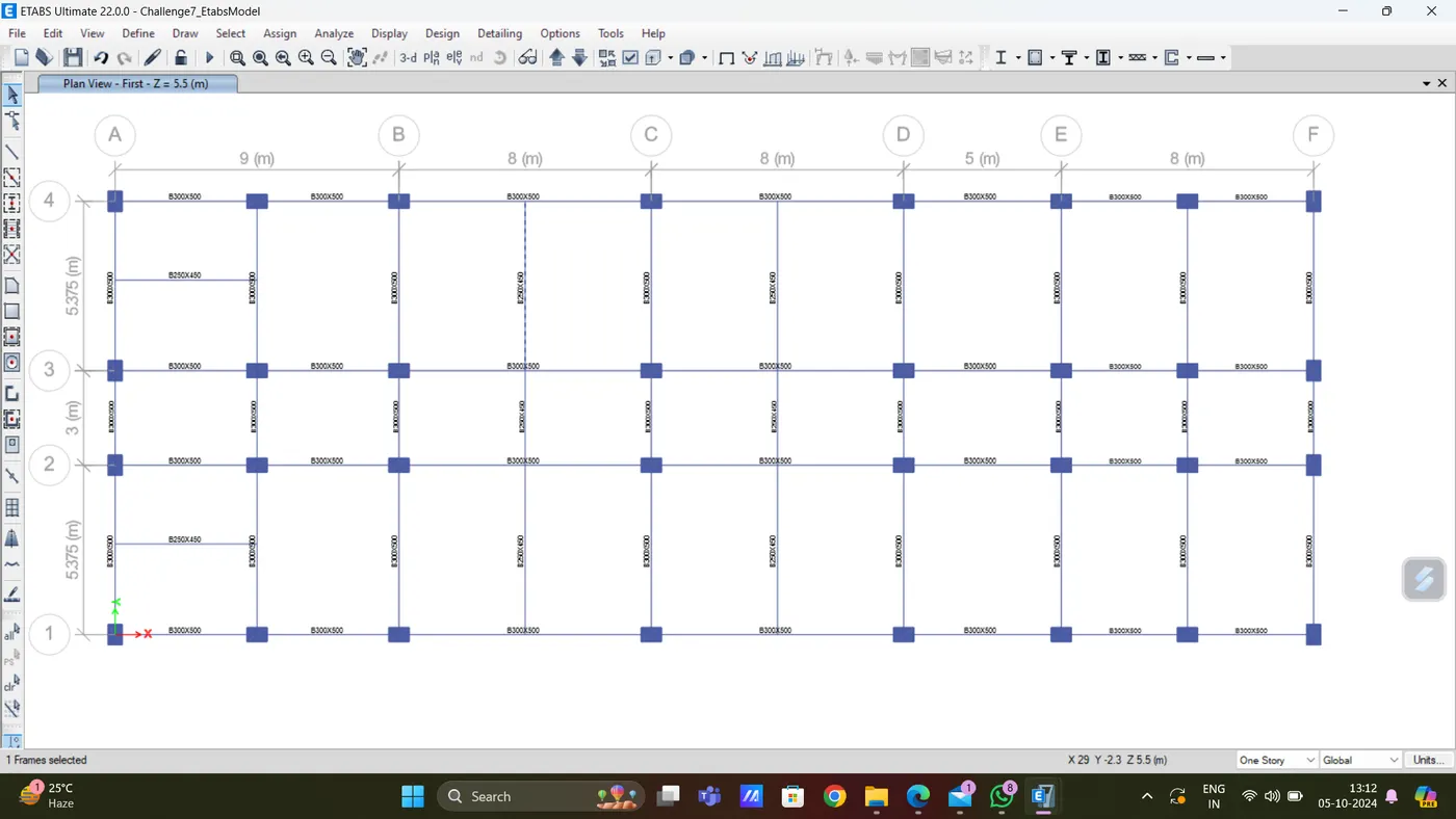
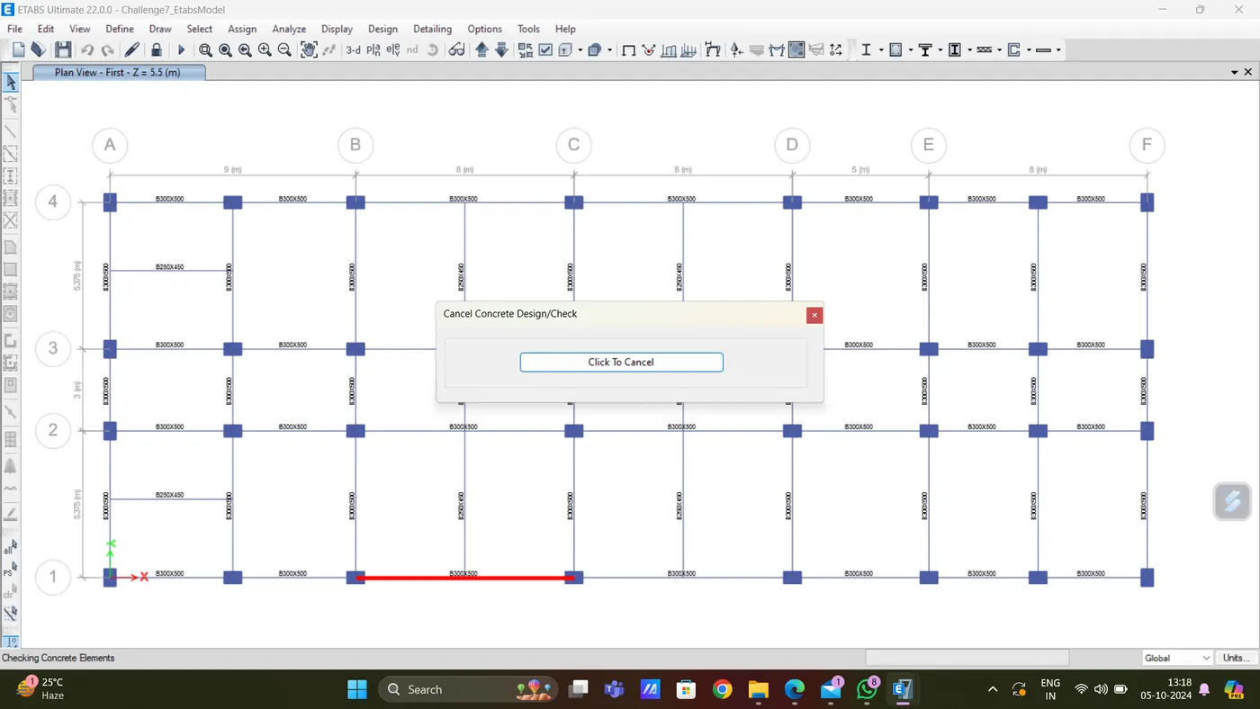
- First, Open the Etabs File and Run the Analysis
Now let's Goto Next Question
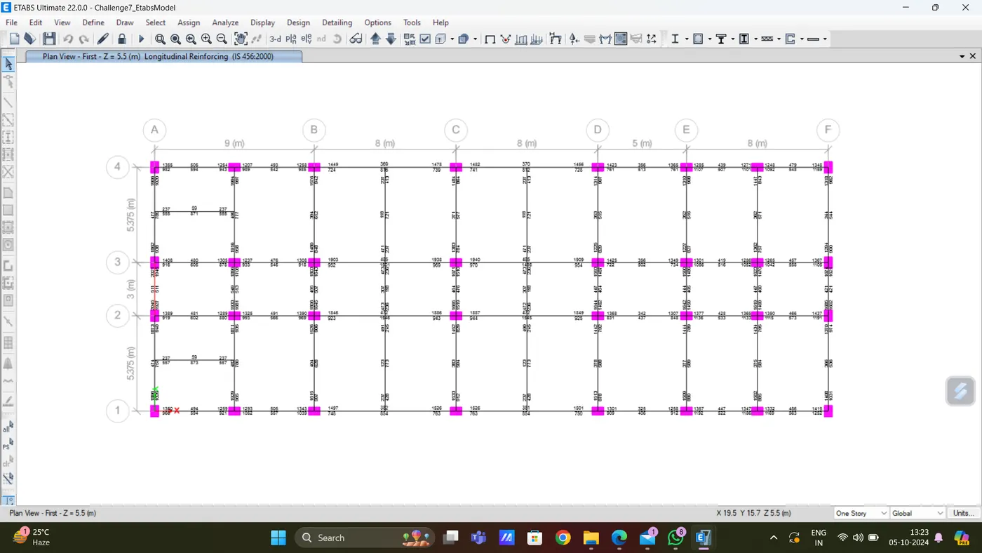
Longitudinal Reinforcement of Beam(mm^2)
- Go to Longitudinal Reinforcement of Beam at Grid-3 from the ETABS (mm^2)
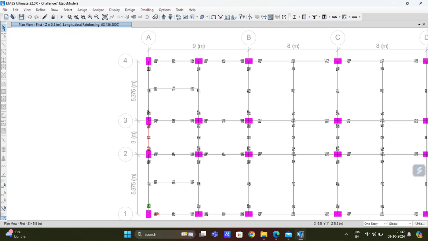
B69 /UDCon-56along Gride-3
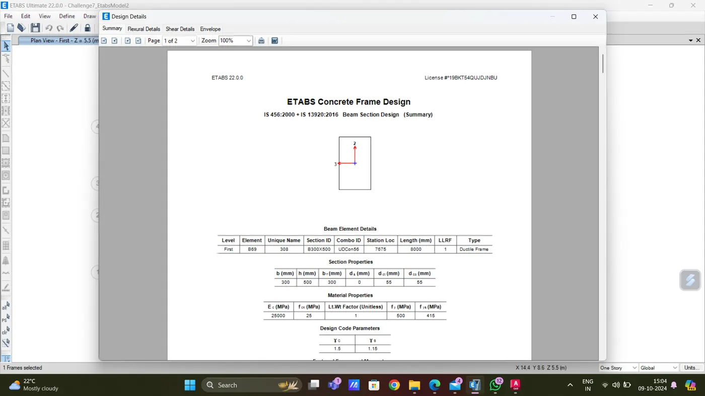
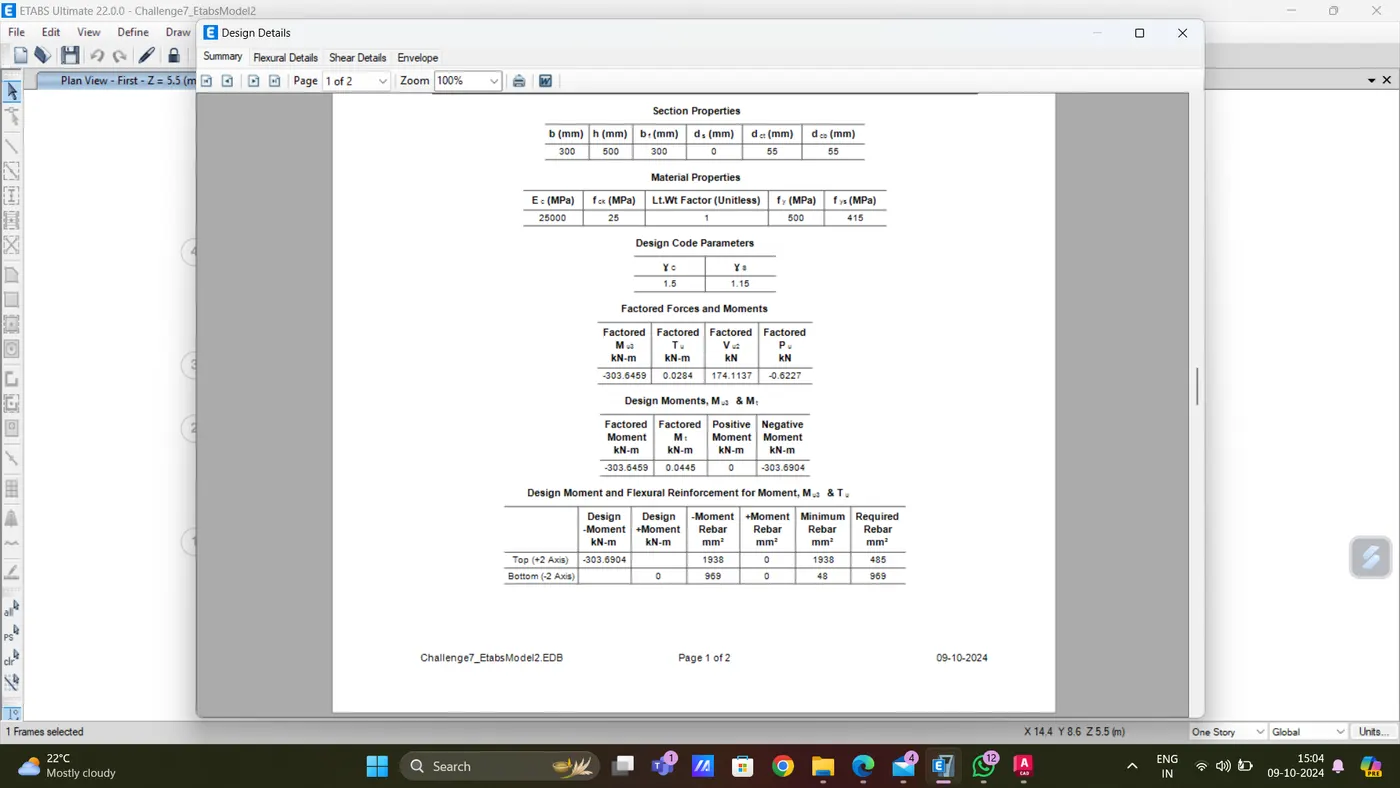
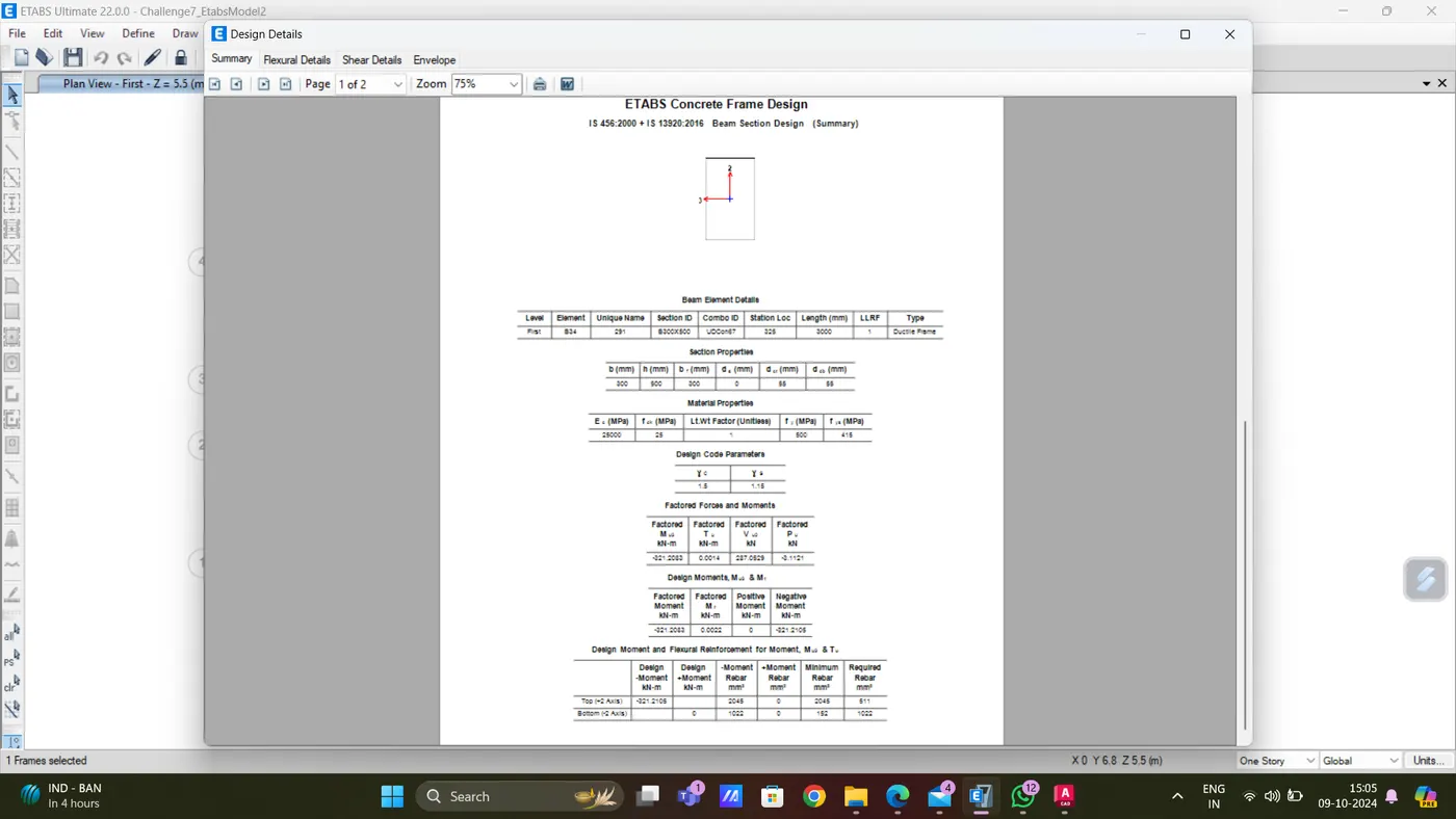
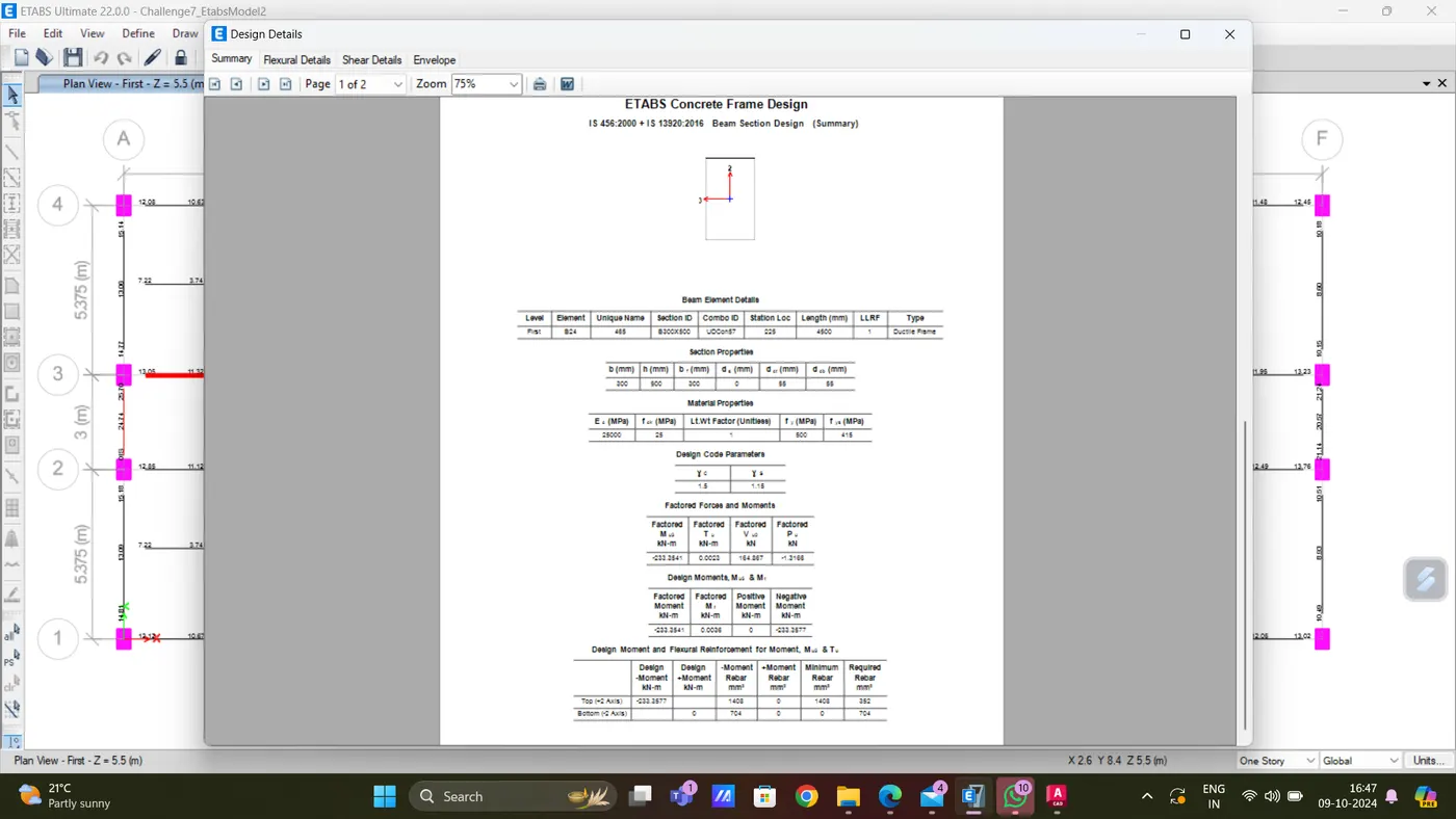
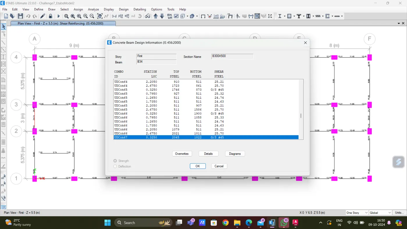
B34/UDcon-67along Gride-A
Shear Reinforcement of Beam(cm^2/1000mm)
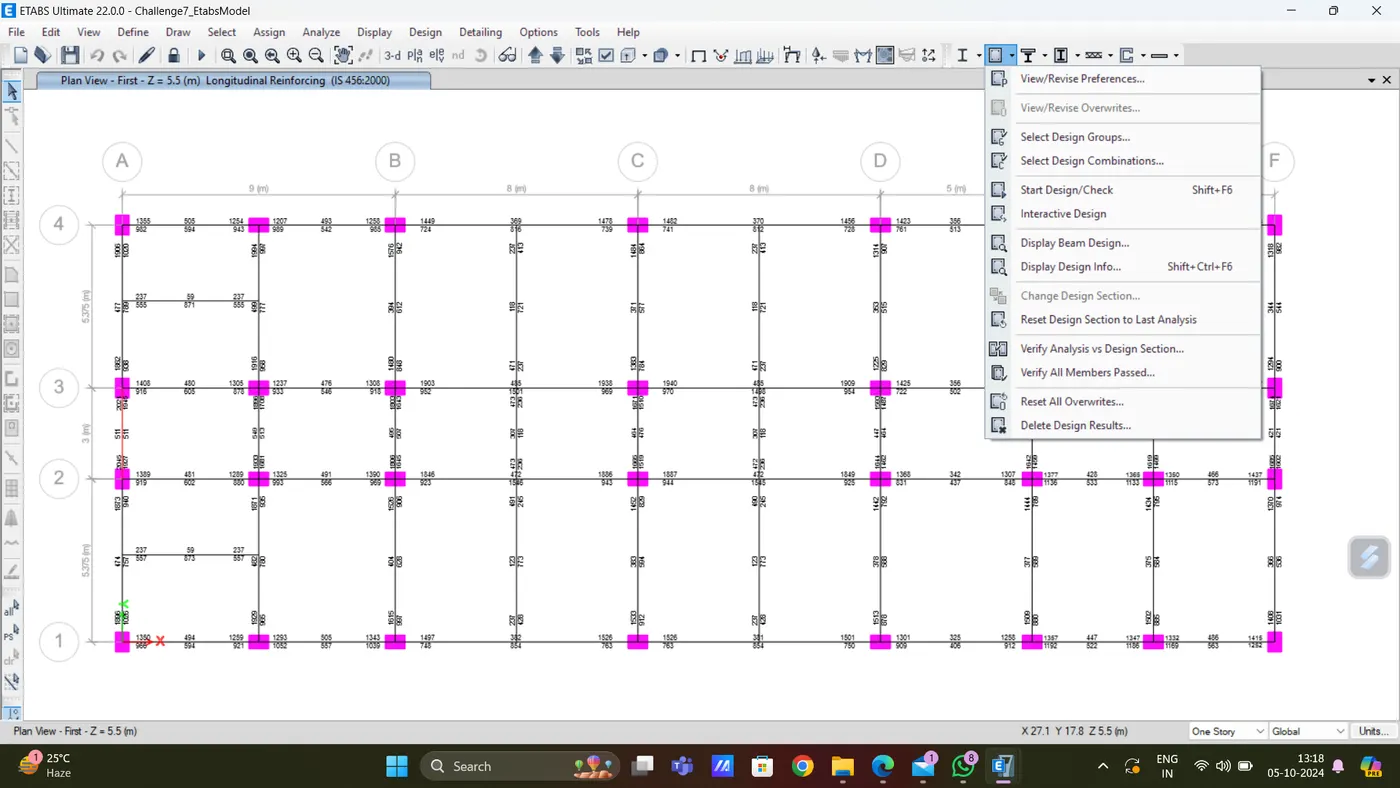
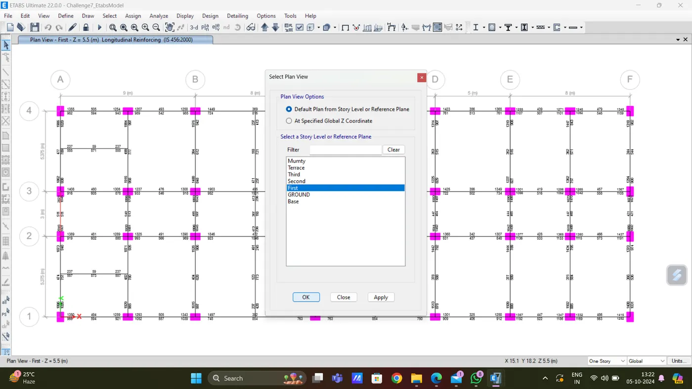
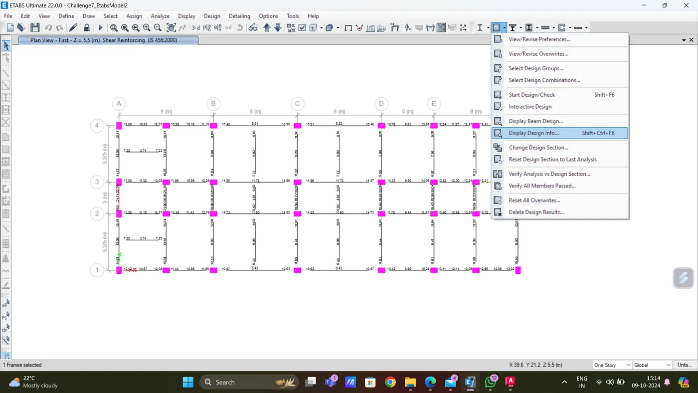
- First go to Concrete frame design > then go to option >go to Display design info
- Select Design output> Shear Reinforcement > press Apply > then Close
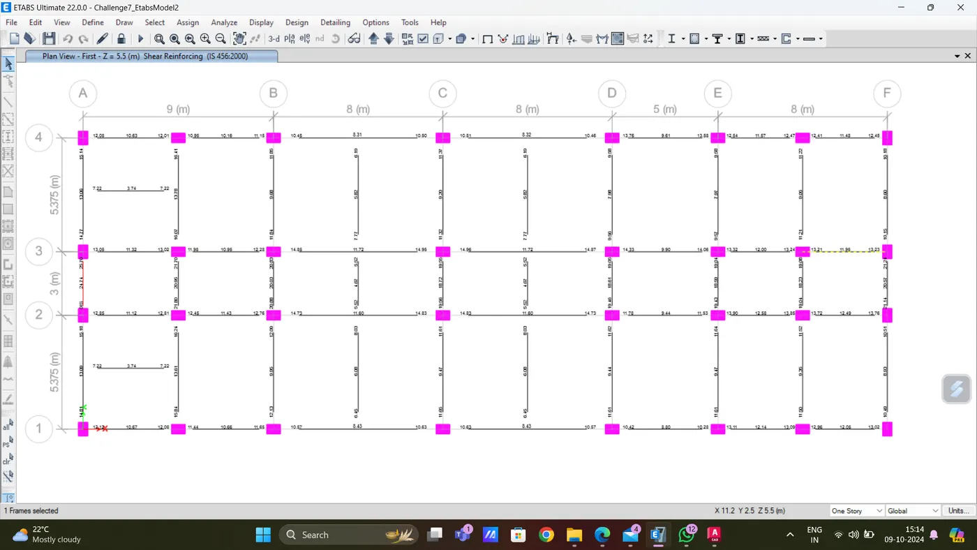
Share Reinforcement of Beam at Grid-3 from the ETABS (cm^2/1000mm)
Share Reinforcement of Beam at Grid-3 from the ETABS (cm^2/1000mm)

Shear Reinforcement of Beam at Grid-3 from the ETABS (cm^2/1000mm)
Share Reinforcement of Beam at Grid-3 from the ETABS (cm^2/1000mm)
Now we have to draw the reinforcement details in the auto-cadd software
First, we have to calculate the rebars Ast for the beam top and bottom section
Seven-span continuous beam along grid 3 Longitudinal reinforcement of beam at grid three from ETABS (mm^2)
Grid 3:
At Top:
1) Maximum Ast at Support = 194
2) Maximum Ast at Middle = 485.
* 2 dia of 32mm = 1606
* 1 dia of 25 mm = 490
Therefore, to satisfy the support, we need to provide two dia of 32mm bar, and additionally, in the middle, we need to provide one dia of 25mm.
At Bottom:
1) Maximum Ast at Support = 1056
2) Maximum Ast at Middle = 1501
* 3 dia of 25mm = 1470
* 1 dia of 16mm = 200.96
Therefore, to satisfy the support, we need to provide three dia of 25mm bar, and additionally, in the middle, we need to provide one dia of 16mm.
- Next, we must draw the Reinforcement diagram of 3 spans continuous beam along Grid-A and provide the reinforcement details.
Grid A:
At Top:
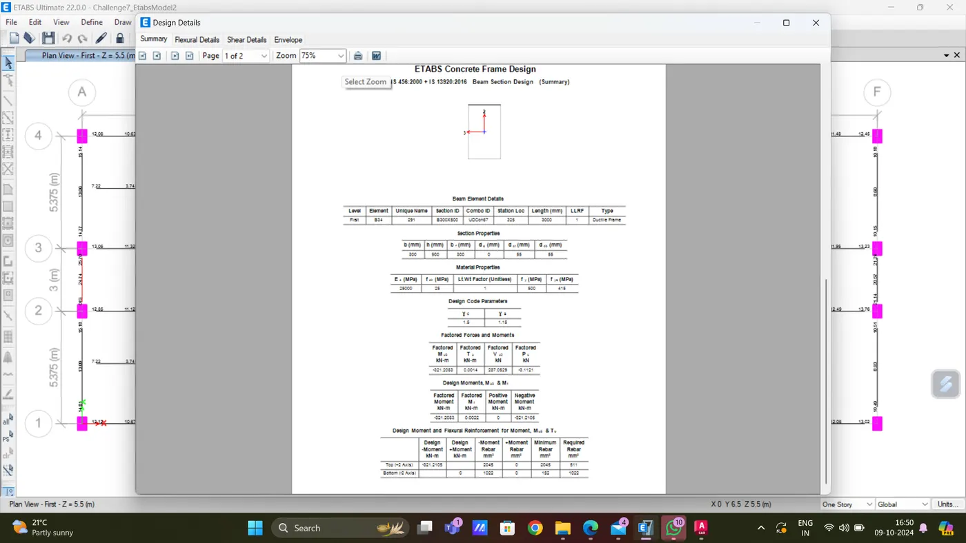
1) Maximum Ast at Support = 2045
2) Maximum Ast at Middle = 477.
* 2 dia of 32mm = 1606
* 1 dia of 25 mm = 490
Therefore, to satisfy the support, we need to provide two dia of 32mm bar and additionally need to provide one dia of 25mm.
At Bottom:
1) Maximum Ast at Support = 1927
2) Maximum Ast at Middle = 789
* 2 dia of 32mm = 1606
* 1 dia of 16mm = 200.96
Therefore, to satisfy the support, we need to provide two dia of 32mm bar, and additionally, in the middle, we need to provide one dia of 16mm.
1) Right-Click the Grid A beam
2) Click Details and switch it to shear details
beam, then the new window popup
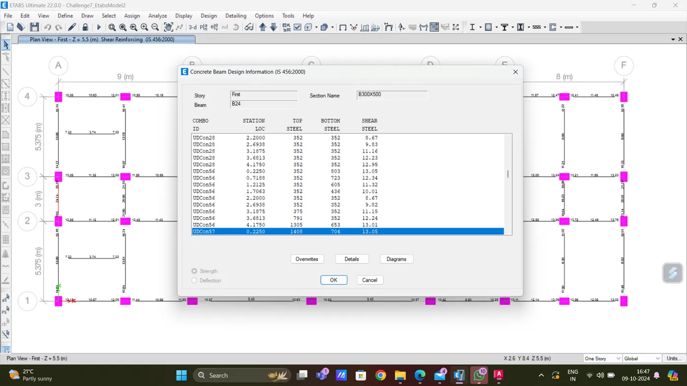
Next, click the Details option in the Concrete beam design tab.
The details will show below:
- 2. Provide reasons for the failure of the middle span along grid A. What are the possible ways this issue can be resolved?
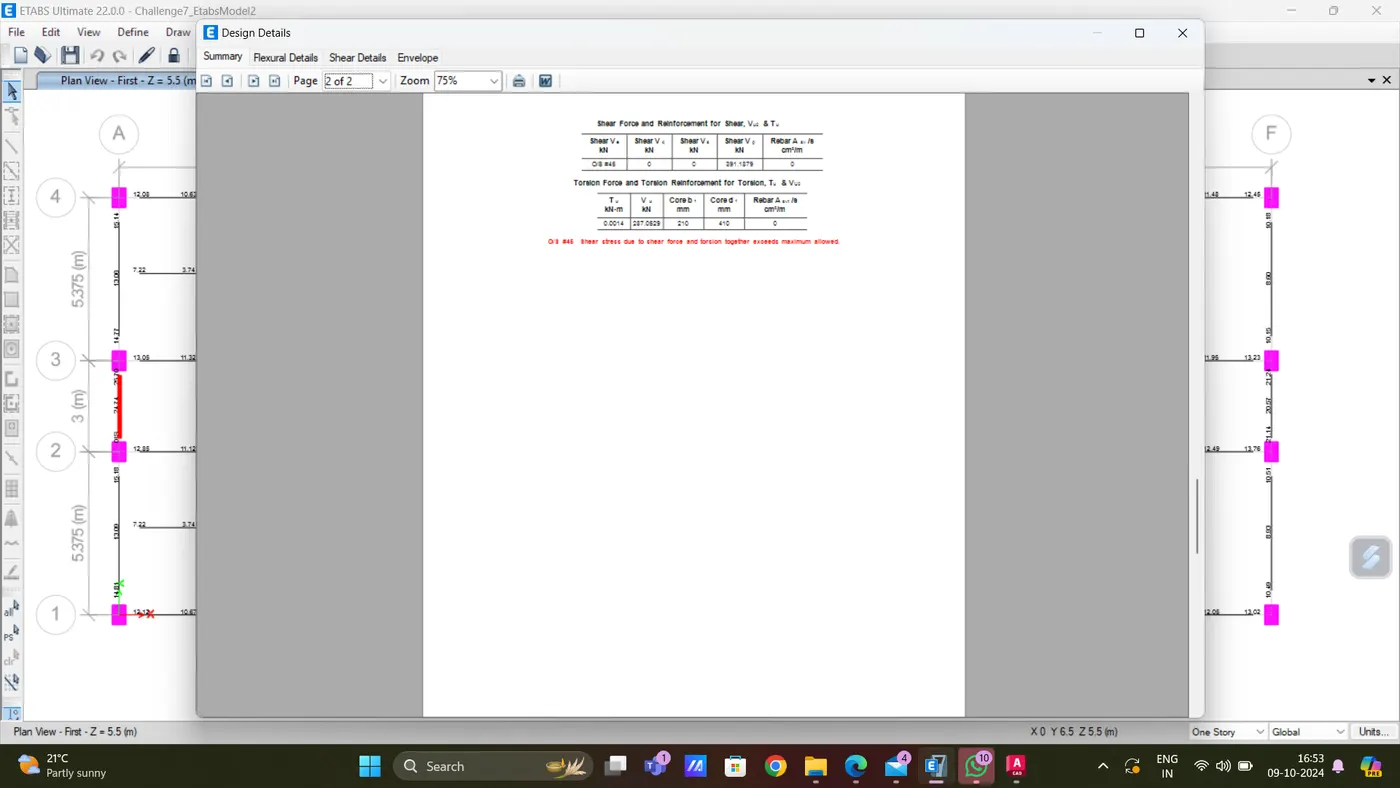
- As we see mid span is indicate bema O/S -Overstressed
3. Calculate the maximum shear force value in any spans in both continuous beams, as per clause 6.3.3 (b) in IS 13920 – 2016. Also, confirm these values from the shear force demand calculated by ETABS. Please note that if longitudinal reinforcement provided is more than required (as per ETABS results), the shear force demand will vary from what is provided by ETABS.
Sway shear force to Right :
Mas = 174 km
Mbh = 293 km
Lab=4.725 m
V.d+l = 92 kN
After substituting the values, we get,
V u,a= 46 kN
V u,b = 230 kN
Sway shear force to the left:
Mah = 234 km
Mbs = 155 km
Lab=4.725 m
V.d+l = 70 kN
After substituting the values, we get,
V u,a= 185 kN
V u,b = 45 kN
Result :
The longitudinal and shear reinforcement details for the two continuous beams are Provided. The beam elevation details were Sketched or drafted it using AutoCAD software.
Reasons and the possible ways this issue can be resolved of failure of the middle span along grid A id provided
The value of the maximum shear force in any one of the spans in both the continuous beams, as per clause 6.3.3 (b) in IS 13920 – 2016. I also confirmed these values from the shear force demand calculated by ETABS.