Reinforcement Detailing of Beams from ETABS output
1. Detailed design of concrete buildings -1
Detailed design of beams in Etabs 2018.
The ETABS file for a G+4 building is provided. Run the analysis and design the RCC Moment ResistingFrame. The following challenge deals specifically with two continuous beams in the 1st floor.
1) 3 span continuous beam along grid A
2) 7 span continuous beam along grid 3
Address the following issues thereafter.
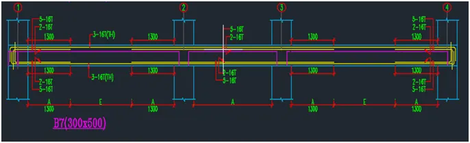
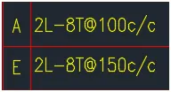
• Provide details of longitudinal and shear reinforcement for the two continuous beams. Sketch the beam elevation details or draft it using AutoCAD software. A sample of how beam elevation details are prepared in consultancy firms is provided below. Participants can prepare it as per their preference:
Provide reasons for failure of the middle span along grid A. What are the possible ways this issue can be resolved?
• Calculate value of the maximum shear force in any one of the spans in both the continuous beams, as per clause 6.3.3 (b) in IS 13920 – 2016. Also, confirm these values from shear force demand calculated by ETABS.Please note that if longitudinal reinforcement provided is more than required (as per ETABS results), the shear force demand will vary from what is provided by ETABS.
AIM:- To run the analysis and design the RCC moment resisting frame for G+4 building:-
a) 3 span continuous beam along grid A
b) 7 span continuous beam along grid 3
To provide details of longitudinal and shear reinforcement for the two continuous beams. To sketch the elevation details or draft it using AutoCAD software.
To provide reasons for failure of the middle span along Grid A and the possible ways to resolve the issue.
To calculate value of the maximum shear force in any one of the spans in both the continuous beams, as per clause 6.3.3 (b) in IS 13920 – 2016. Also, confirm these values from shear force demand calculated by ETABS.
INTRODUCTION:- All the steps are going to be mentioned along with step by step procedure
PROCEDURE:
- Download the file and open the ETABS software.
- Check the model
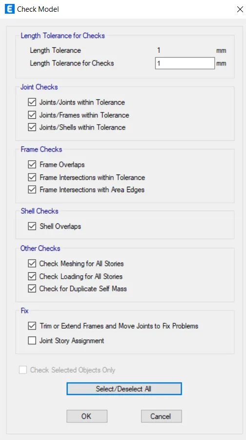
- Model has been checked

- Go to concrete frame design > select preferences
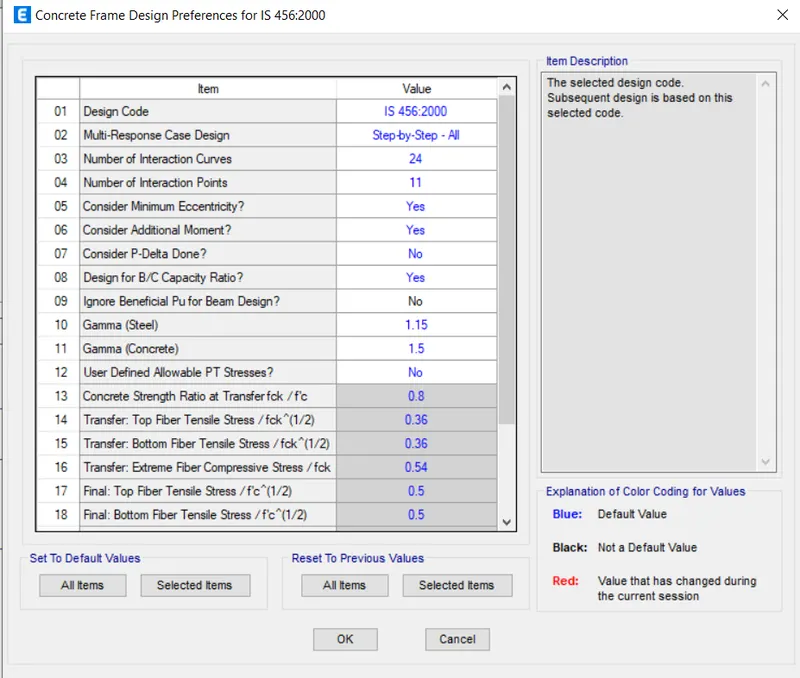
- Click on concrete frame design
- Choose it as total longitudinal reinforcing
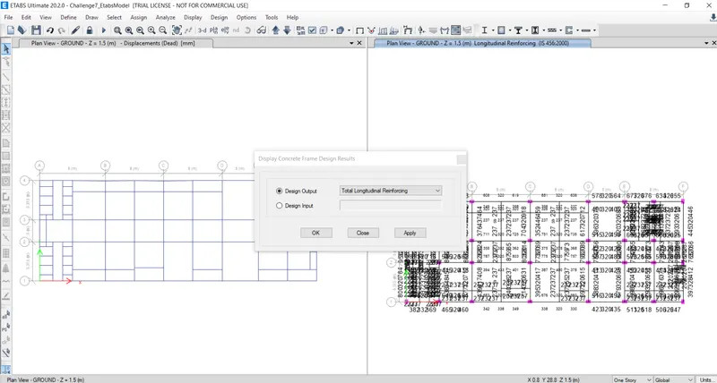
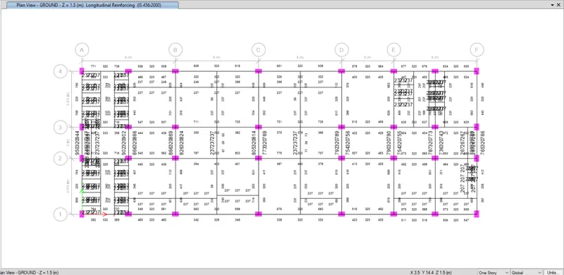
- Choose it as shear reinforcing steel
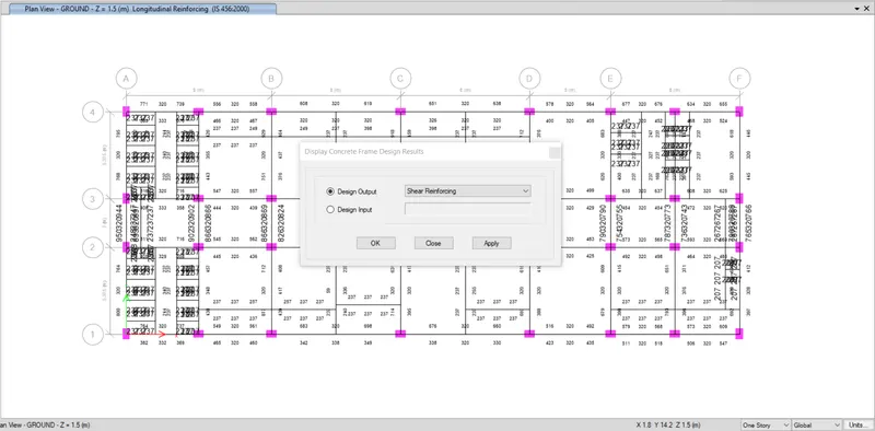
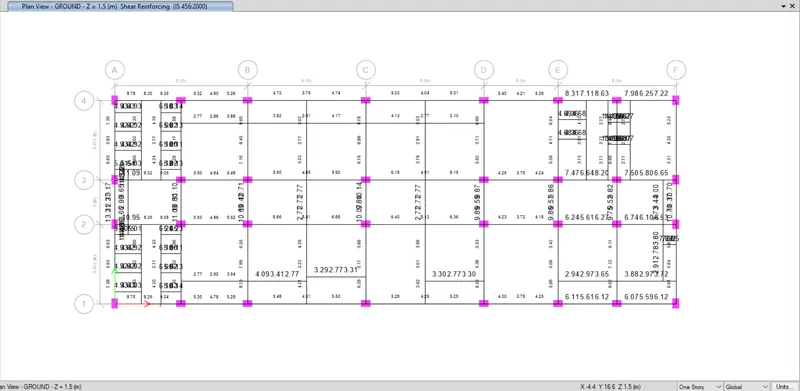
- Right Click on the individidul members
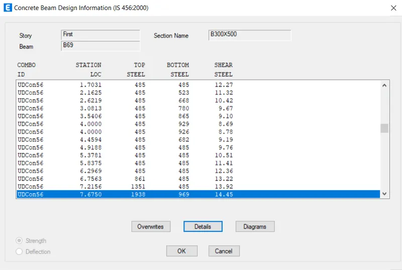
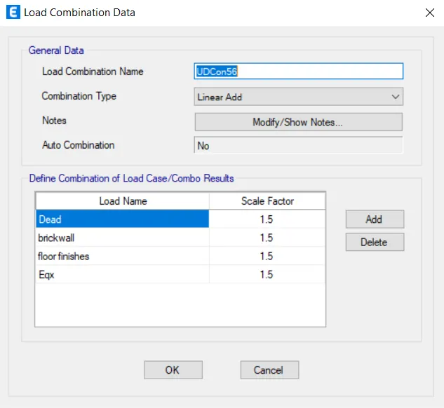
- Check the load combinations for the respective members
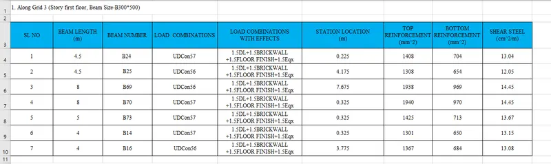
1. Provide details of longitudinal and shear reinforcement along grid A and grid 3 with the help of excel sheet:-
Along grid 3
Along grid A

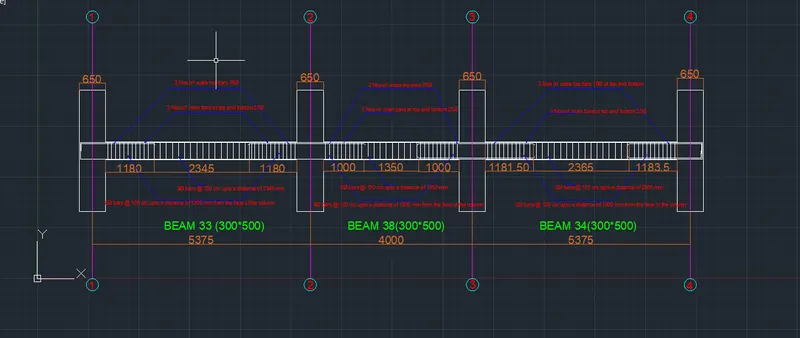
Beam 38 (Along grid A)

- Provide 3 nos of 25 mm dia bars at the top and bottom of the beam
- Provide 2 nos of 16 mm extra bars at the top right and left hand of the beam respectively
Beam 34 (Along grid A)

- Provide 3 nos of 25 mm dia bars at the top and bottom of the beam
- Provide 3 nos of 16 mm extra bars at the top right and left hand of the beam respectively
Beam 33 (Along grid A)

- Provide 3 nos of 25 mm dia bars at the top and bottom of the beam
- Provide 3 nos of 16 mm extra bars at the top right and left hand of the beam respectively
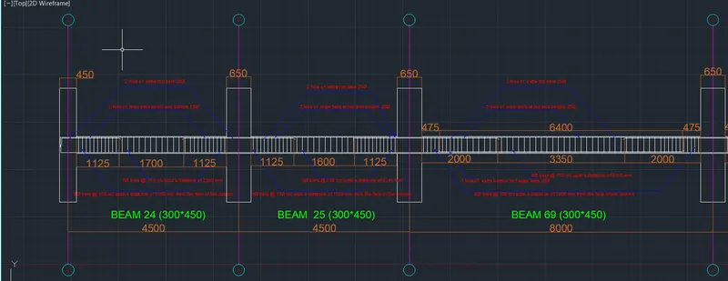
Beam 24 (Along grid 3)

- Provide 2 nos of 25 mm dia bars at the top and bottom of the beam
- Provide 2 nos of 20 mm extra bars at the top right and left hand of the beam respectively
Beam 25 (Along grid 3)

- Provide 2 nos of 25 mm dia bars at the top and bottom of the beam
- Provide 2 nos of 20 mm extra bars at the top right and left hand of the beam respectively
Beam 69 (Along grid 3)

- Provide 2 nos of 25 mm dia bars at the top and bottom of the beam
- Provide 2 nos of 20 mm extra bars at the top right and left hand of the beam respectively
- Provide 2 nos of 20 mm extra bars at the bottom part of the mid-span respectively
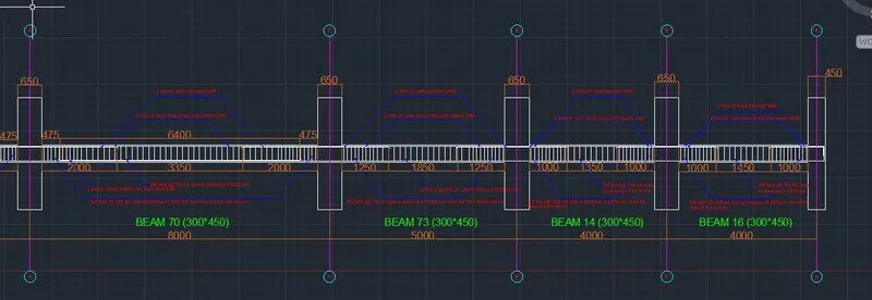
Beam 70 (Along grid 3)

- Provide 2 nos of 25 mm dia bars at the top and bottom of the beam
- Provide 2 nos of 20 mm extra bars at the top right and left hand of the beam respectively
- Provide 2 nos of 20 mm extra bars at the bottom part of the mid-span respectively
Beam 73 (Along grid 3)

- Provide 2 nos of 25 mm dia bars at the top and bottom of the beam
- Provide 2 nos of 20 mm extra bars at the top right and left hand of the beam respectively
Beam 14 (Along grid 3)

- Provide 2 nos of 25 mm dia bars at the top and bottom of the beam
- Provide 2 nos of 20 mm extra bars at the top right and left hand of the beam respectively
Beam 16 (Along grid 3)

- Provide 2 nos of 25 mm dia bars at the top and bottom of the beam
- Provide 2 nos of 20 mm extra bars at the top right and left hand of the beam respectively
2. Shear reinforcement calculations
Grid line A (B38)
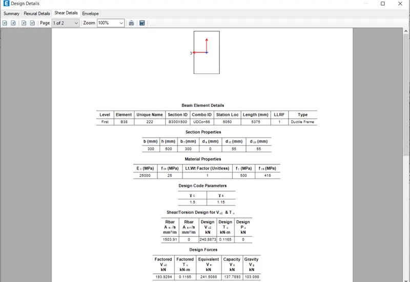
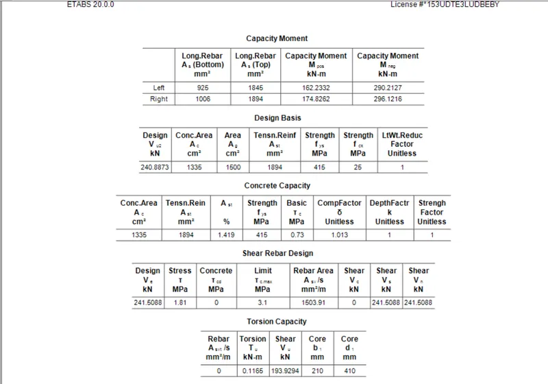
From ETABS output, Design shear force, V = 241.51 KN
Provide 2 legged 8 mm dia stirrups with 100 mm spacing
Providing 30 mm clear cover, Asv = 2*3.14/4*10^2 = 100 mm^2
Effective depth = 500-60 = 440 mm
Vus = 0.87*fy*Asv*d/Sv = 0.87*415*100*440/100 = 158.862 KN
Since Vus < V ( Design shear force), hence safe.
So provide 2 legged 8 mm dia stirrups with 100 mm spacing.
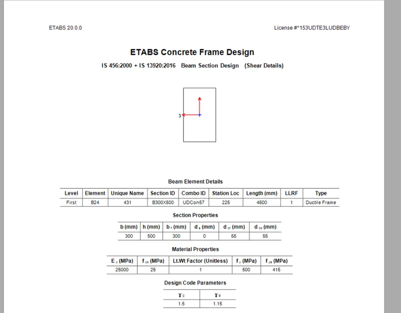
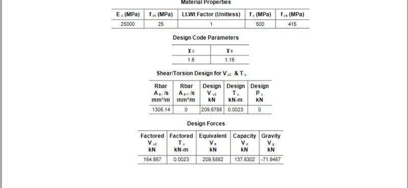
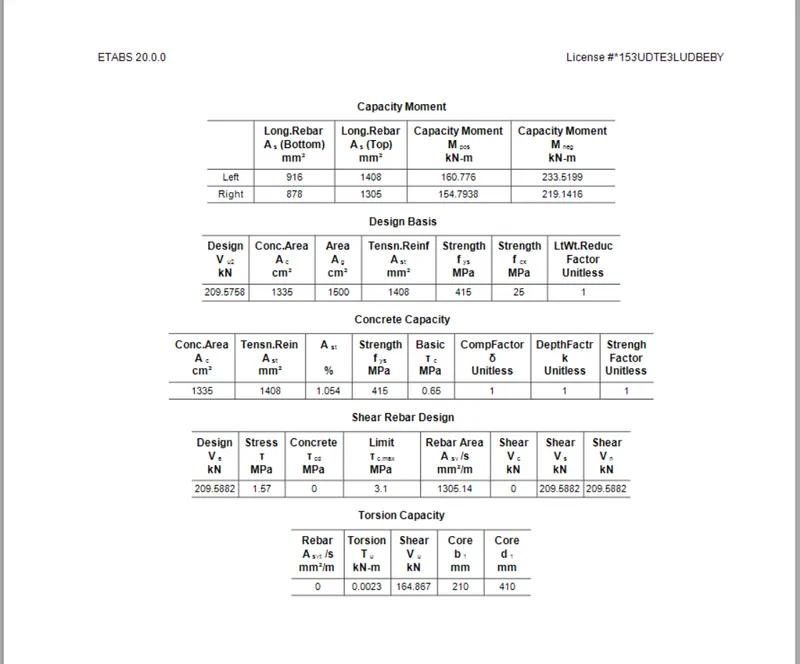
From ETABS Design shear force = 209.58 KN
Provide 2 legged 8 mm dia stirrups with 100 mm spacing
Providing 30 mm clear cover, Asv = 2*3.14/4*10^2 = 100 mm^2
Effective depth = 500-60 = 440 mm
Vus = 0.87*fy*Asv*d/Sv = 0.87*415*100*440/100 = 158.862 KN
Since Vus < V ( Design shear force), hence safe.
So provide 2 legged 8 mm dia stirrups with 100 mm spacing.
3. Reasons for failure of the middle span along grid 3
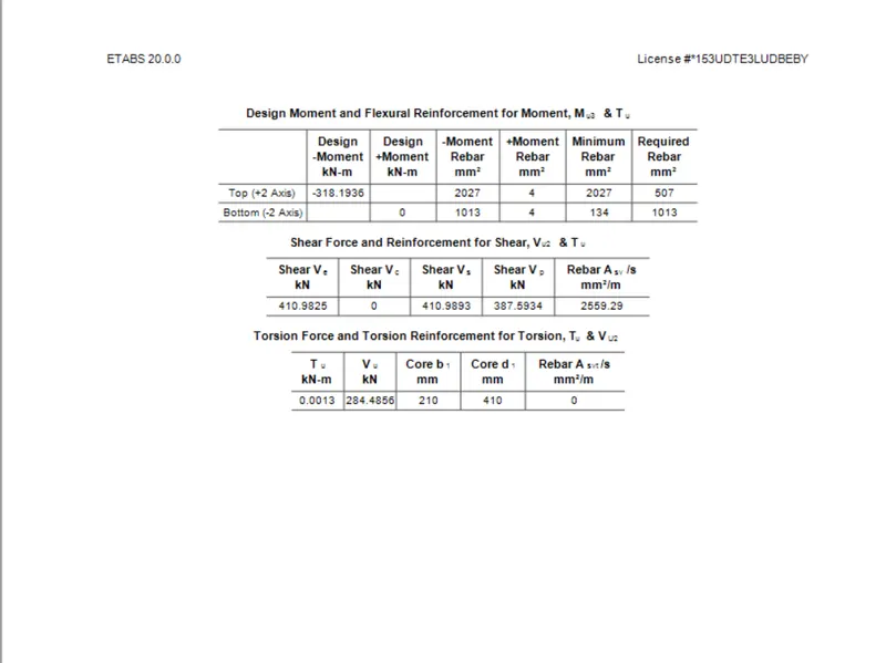
- From the above ETABS output it has been shown that the limiting value of shear force and developed shear force remains the same. Hence it is not safe
The possible ways to solve this problem can be :-
a) By providing higher grade of concrete
b) By reducing effective depth
4. Calculate the value of maximum shear force
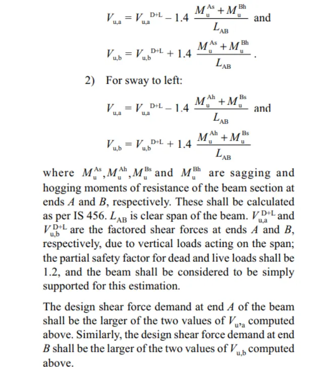
- As per IS 13920-2016, new load combinations has been added for sway combination, the partial factor for dead and live load is considered to be 1.2
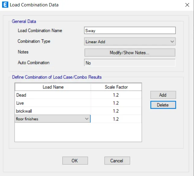
Sway to left:-
V(u+a) = 70.58 KN, Mu (As) = 160.776 KN and Mu (Bh) = 233.59 KN
Vu,a = 70.58 - 1.4*(160.774+233.54)/3.9 = -70.998 KN
Vu,a = 70.58 + 1.4*(160.774+233.59)/3.9 = 212.14 KN
Sway to right:-
V(u+a) = 70.58n KN, Mu (Ah) = 154.79 KN, Mu (Bs) = 219.14 KN
Vu,a = 70.58 - 1.4*(154.79+219.14)/3.9 = -54.06 KN
Vu,b = 70.58 + 1.4*(154.79+219.14)/3.9 = 195.22 KN
5. Detailing of beams using AutoCAD
Grid A
Grid 3
RESULTS: The folloxing has been illustrated properly along with results:-
a) Analysis and design the RC moment frame for G+4 building
b) Providing details of longitudinal and shear reinforcement for beam along with elevation details
c) Providing reasons for failure of the middle span along grid A
d) Calculating value of maximum shear forces in any of the span