Reinforcement Detailing of Beams from ETABS output
Detail design of beams in Etabs 2018.
The ETABS file for a G+4 building is provided. Run the analysis and design the RCC Moment ResistingFrame. The following challenge deals specifically with two continuous beams in the 1st floor.
1) 3 span continuous beam along grid A
2) 7 span continuous beam along grid 3
Address the following issues thereafter.
• Provide details of longitudinal and shear reinforcement for the two continuous beams. Sketch the beam elevation details or draft it using autocad software. A sample of how beam elevation details is prepared in consultancy firms is provided below. Participants can prepare it as per their preference:
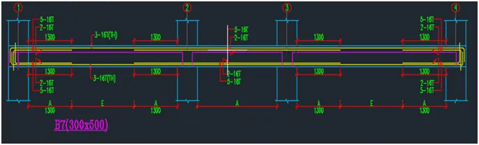
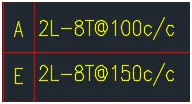
• Provide reasons for failure of the middle span along grid A. What are the possible ways this issue can be resolved?
• Calculate value of the maximum shear force in any one of the spans in both the continuous beams, as per clause 6.3.3 (b) in IS 13920 – 2016. Also, confirm these values from shear force demand calculated by ETABS.Please note that if longitudinal reinforcement provided is more than required (as per ETABS results), the shear force demand will vary from what is provided by ETABS.
AIM :
The objective of the project is to analyse the given project and to extract the detailing drawing for the mentioned beams in 2 grid lines in vertical and horizontal.
Procedure :
Open the attachment file in etabs.
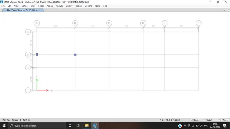
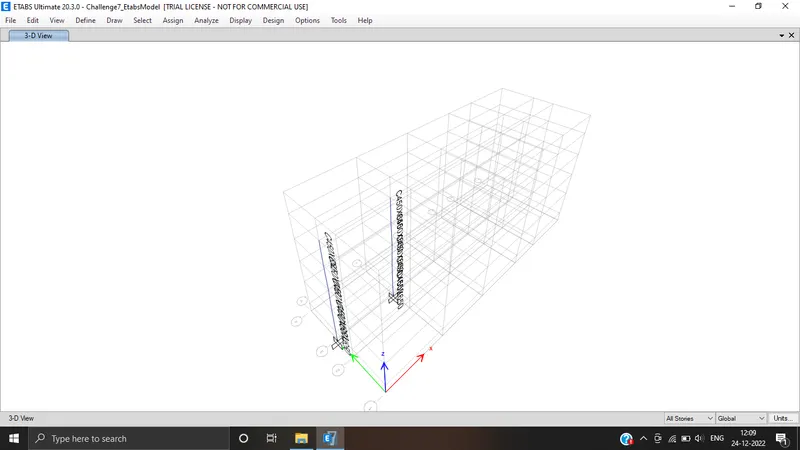
Select two columns.
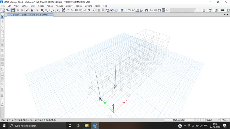
Then run the analysis .
Then click the concrete frame icon.
After clicking the icon it starts checking concrete design.
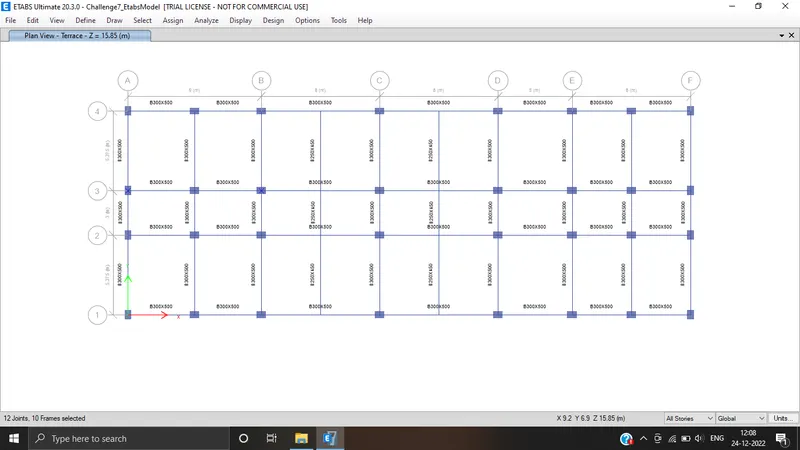
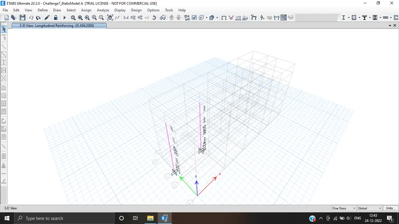
Longitudinal reinforcement beams.
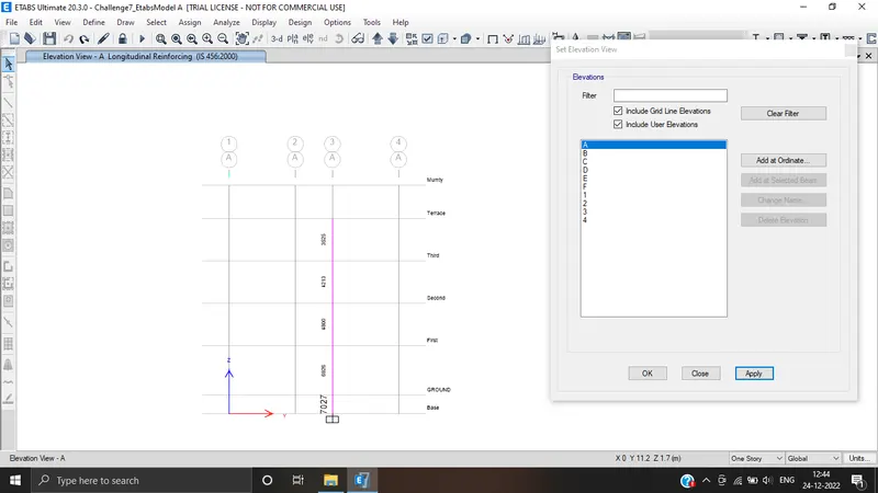
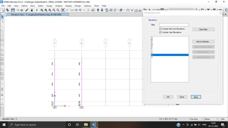
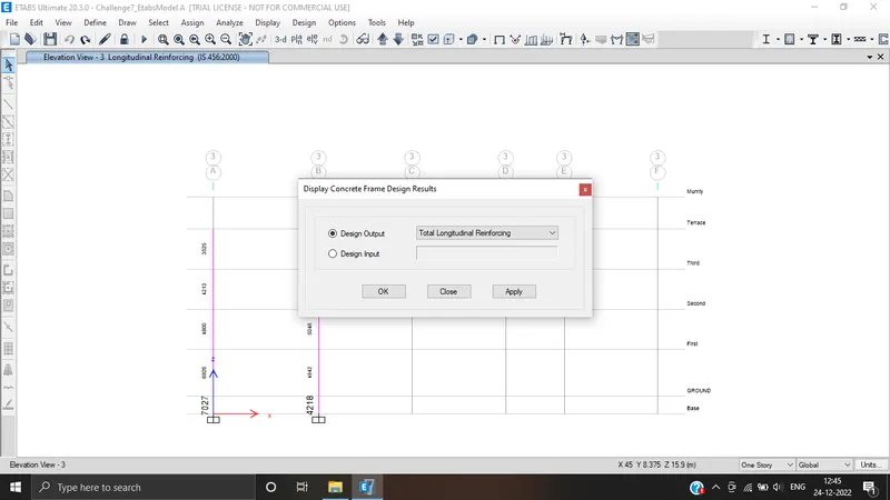
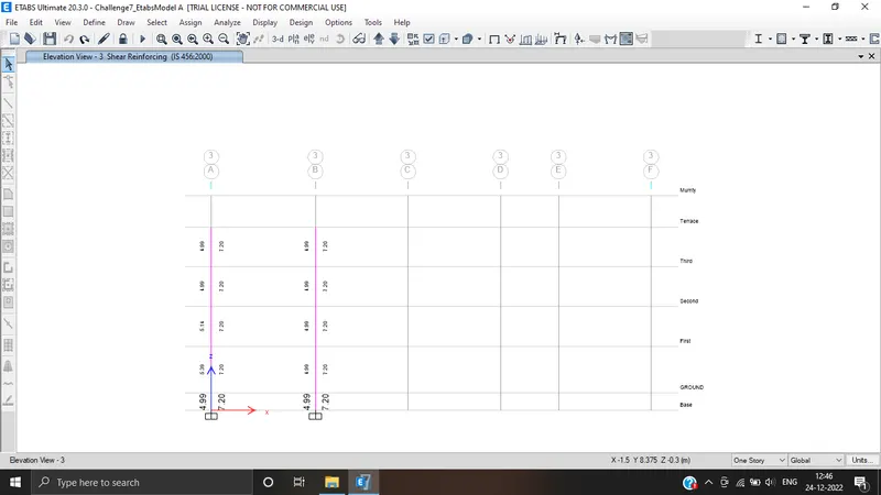
Shear force right.
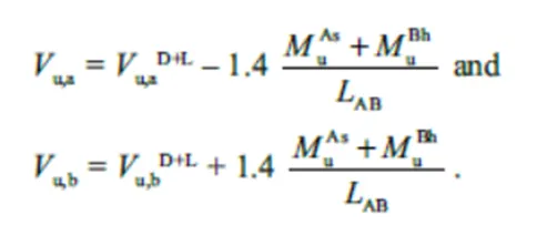
Shear force left.
As per IS 13920-2016 clause 6.3.3 (b):
Mas = 303 KN/m,
Mah = 321 KN/m
Mbh =319 KN/m,
Mbs =304 KN/m
Lab = 2.35 m,
Lab = 2.35 m
Vu,a(d+l) = 22.63
Vu,b(d+l) =21
Vu,a = 348 KN
Vu,a = 349 KN
Vu,b = 391 KN
Vu,b = 393 KN
TOP GRID A:
Maximum Ast at support = 2045
Maximum Ast at middle = 511
3 of 25 mm = 1473
3 of 20 mm = 942
BOTTOM GRID A:
Maximum Ast at support = 1945
Maximum Ast at middle = 511
3 of 25 mm = 1473
3 of 20 mm = 942
Right click the grid A beam.
Click details and switch it into shear details.
As per clause 6.3.3 the design force of equivalent Ve = 414.5 KN.
Shear force under the linear analysis as per the load combination of UD cons67 = 287 KN.
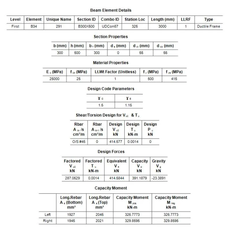
Shear capacity in beam as per drawing:
(As per IS 456-2002 clause 40.4)
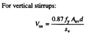
Fy = 415 N/mm2
Asv = 151 mm2
d = 500 mm
Sv = 100 mm
Vus = 272.6 KN/m
Reason for failure of middle span along gris A, possible way to resolve this issue?
Shear stress = Load / Area
1). Reduse the loading (or)
2). Increase the loading
3). Shear capacity of concrete, it varies w.r.t the grading of concrete
If we use some higher grade for this beam alone, We can increase the shear capacity of the beam, We can make it Pass.
RESULT:
Designed successfully in detail from the ETABS software.
Details of longitudinal and shear reinforcement for the two continuous beams.
Calculated the value of maximum shear force in the continuous beams using the ETABS.