Radar Mast & Final Assembly of Yacht
Radar mast and Assemble the Yacht
Note: Check the PPT attached in the files upload area to get the drive link(Unable to add all ZIP files due to the size limitation).
1. Radar Mast:
Aim: To model the Yacht's Radar Mast using SolidWorks.
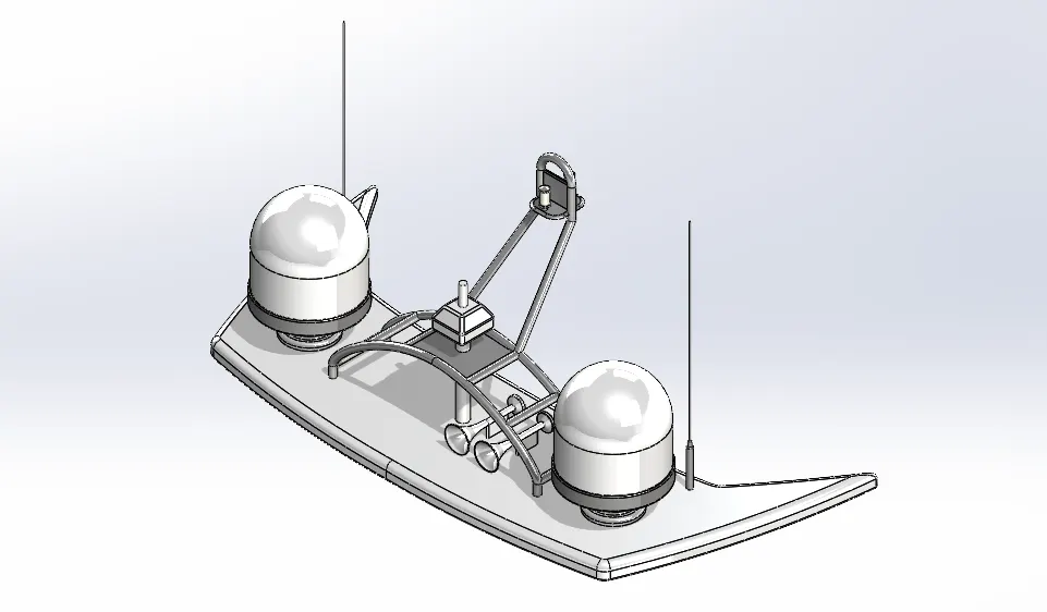
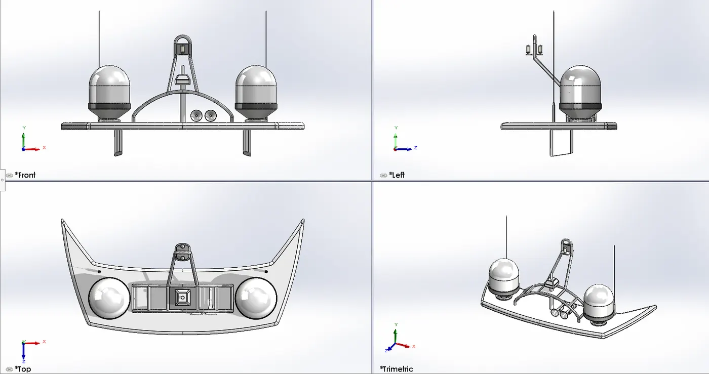
The Radar Mast model was created as per the given dimensions.
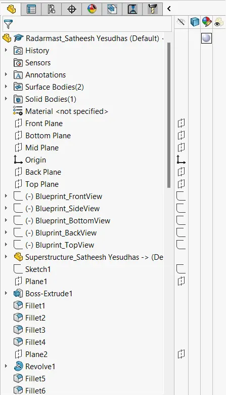
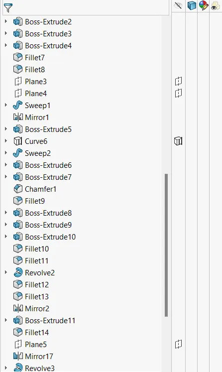
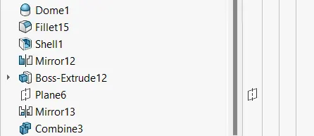
The Radar Mast design was modeled by using different commands such as,
- Surface Extrude
- Mirror
- Fillet
- Sweep
- Smart Dimensions
- Appearance
- Cut Extrude
- Reference Plane
- 3D sketch
- Revolve
- Dome
- Chamfer
2. Yacht Assembly:
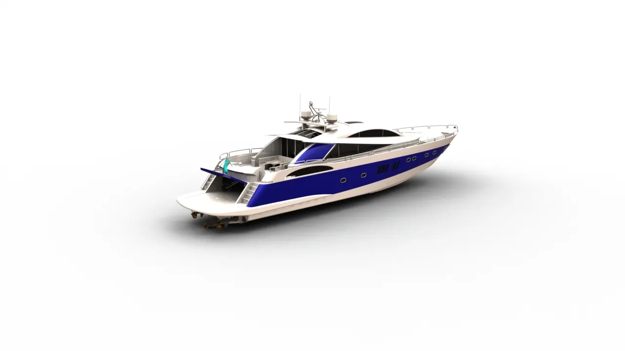
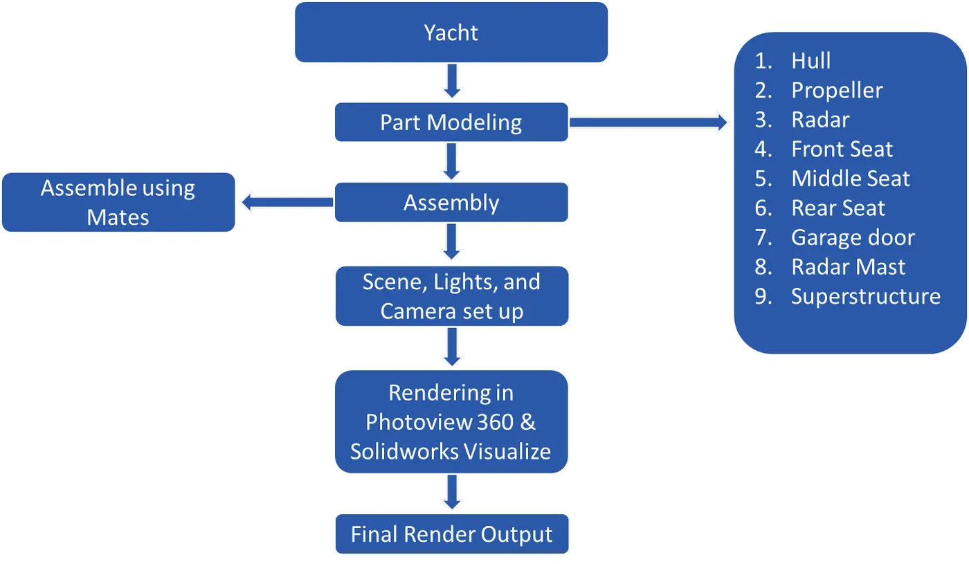
Aim: The aim of this project is to create a model of a Yacht with different parts like Hull, Propeller, Radar, Garage door, front seat, Rear seat, Middle seat, Radarmast, and Superstructure assembled with different parts of the Yacht, and create a photorealistic model of the chopper and render the model by using software like Solidworks photo view 360 and Solidworks Visualize.
Introduction:
- A yacht is a sailing or power vessel used for pleasure, cruising, or racing. There is no standard definition, though the term generally applies to vessels with a cabin intended for overnight use.
- In this report we can see the detailed view of Yacht modeling and rendering using Solidworks and Solidworks Visualize.
Design Methodology/ Approach:
Assembly of Yacht:
The following parts are used for model and assembly in solid works,
- Hull
- Propeller
- Radar
- Garage door
- Front seat
- Rear seat
- Middle seat
- Radarmast and
- Superstructure
Description of Individual Parts:
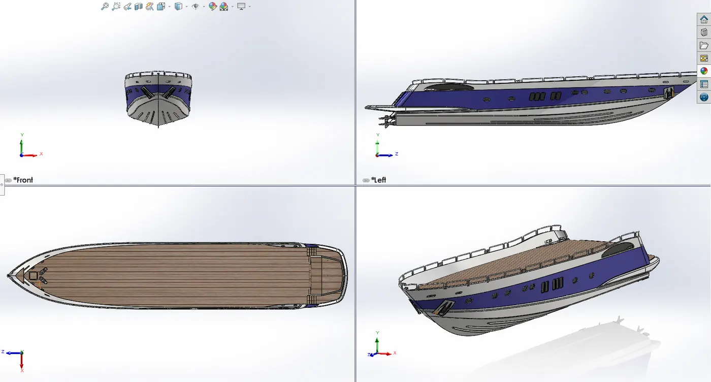
1. Hull:
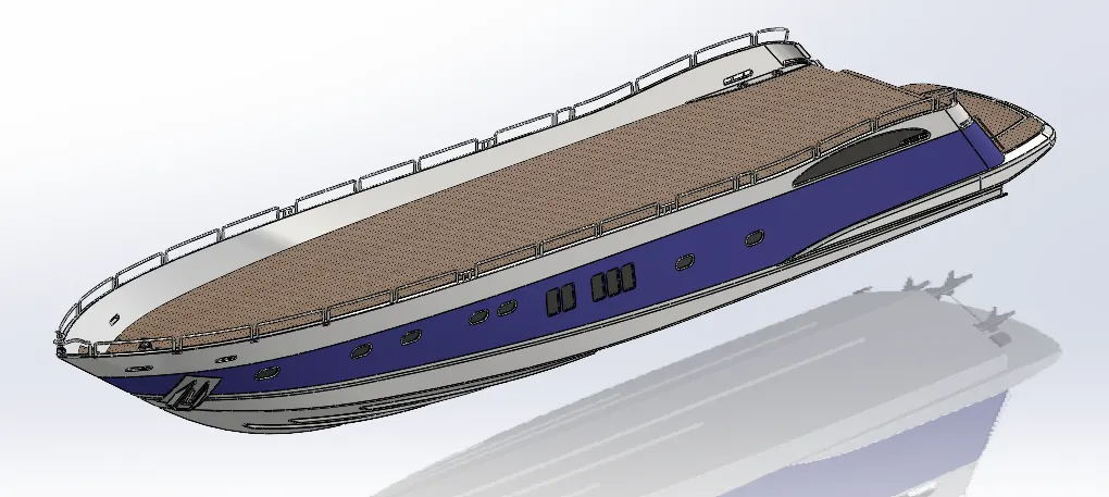
The hull is the watertight body of a vessel, it envelopes its structure and creates the frame. It keeps the vessel afloat and stabilizes it.
The following Hull is designed as per the given dimensions.
Commands used to create Hull:
- Sketch
- Project Curve
- Surface Loft
- Surface Trim
- Surface Extrude
- Surface Knit
- Sweep
- Boss Extrude
- Revolve
- Dome
- Helix/Spiral
- Linear Pattern
- Add/Delete Face
- Thin Extrude
- Surface Fill
- Shell
- Cut Extrude
- Fillet
- Chamfer
- Thin cut Extrude
- Split
- Split Line
- Offset Surface
- Mirror
- Decals
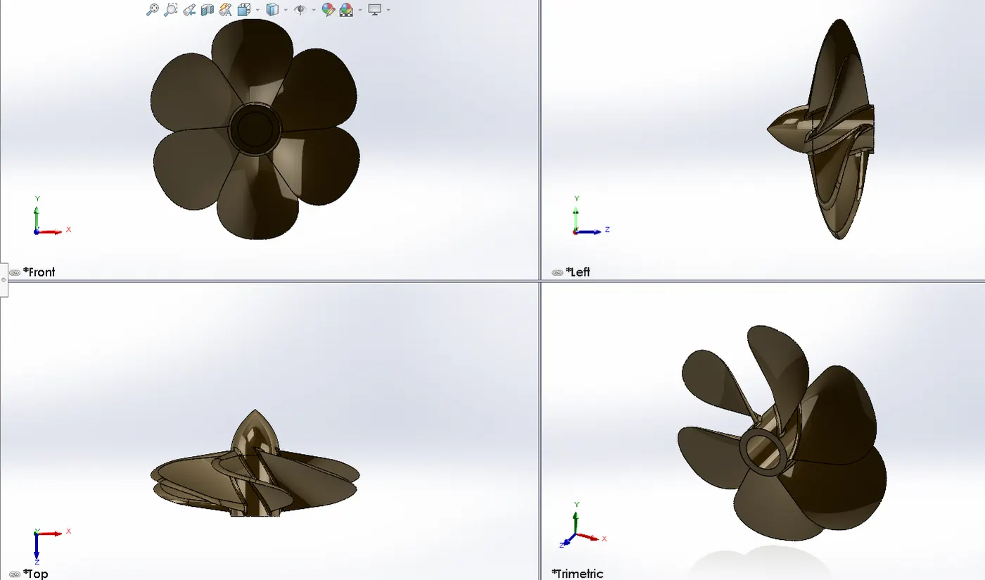
2. Propeller:
Propeller is a device that consists of a central hub with radiating blades placed and twisted so that each forms part of a helical surface and that is used to propel a vehicle (such as a ship or airplane)
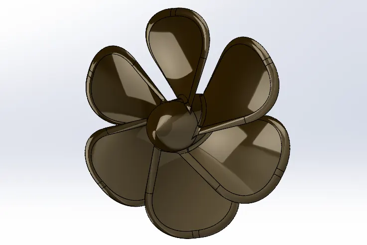
Commands used to create Propeller:
- Sketch
- Revolve
- Loft
- Cut Extrude
- Circular Pattern
- Fillet
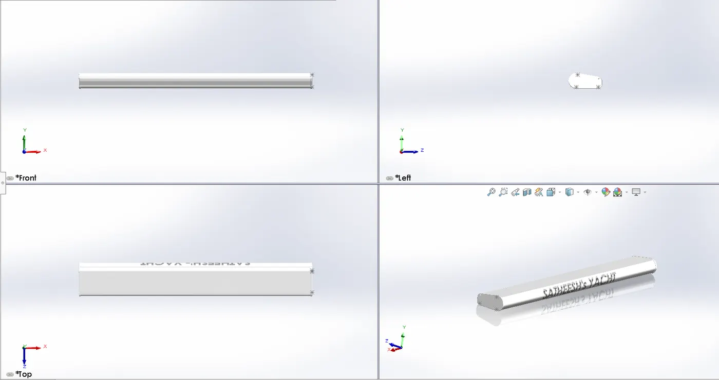
3. Radar:
Radar is used to detect other ships and land barriers, to provide bearings and distances for the prevention of collisions and navigation at sea.
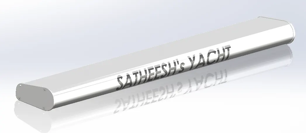
Commands used to create Radar:
- Boss Extrude
- Cut Extrude
- Sketch Pattern
- Split Line
- Mirror
- Fillet
4. Garage Door:
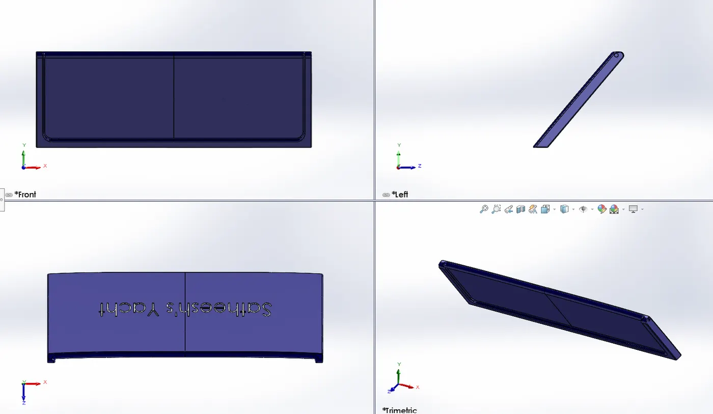
The garage door body was 'Split' from the hull and imported separately for modelling. The garage door was mated with the hull garage during the assembly.
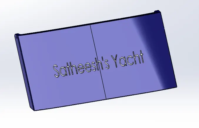
Commands used to create Garage Door:
- Cut Extrude
- Shell
- Mirror
- Fillet
- Text
5. Front Seat:
Front seat was placed in front of the Superstructure on the hull. It was designed after importing the deck surface of the Hull as interface surface.
The Front Seat model was created as per the given dimensions.
The Front Seat design was modeled by using different commands such as,
- Surface Extrude
- Mirror
- Fillet
- Surface Trim
- Surface Knit
- Surface Fill
- Smart Dimensions
- Appearance
- Cut Extrude
- Reference Plane
- Surface Sweep
- 3D sketch
- Revolve
- Dome
- Chamfer
6. Middle Seat:
Middle seat was placed close behind the back door of the Superstructure in the shaded area.
The Middle Seat model was created as per the given dimensions.
The Middle Seat design was modeled by using different commands such as,
- Extruded boss/base
- Cut Extrude
- Mirror
- Fillet
- Smart Dimensions
- Appearance
- Cut Extrude
- Reference Plane
7. Rear Seat:
Rear seat was placed over the garage behind the Superstructure. It was designed after importing the deck surface of the Hull as interface surface.
The Rear Seat model was created as per the given dimensions.
The Rear Seat design was modeled by using different commands such as,
- Surface Extrude
- Boss Extrude
- Mirror
- Fillet
- Surface Trim
- Surface Knit
- Surface Fill
- Surface Loft
- Sweep
- Smart Dimensions
- Appearance
- Cut Extrude
- Reference Plane
- Surface Sweep
- 3D sketch
- Revolve
- Surface Offset
- Chamfer
8. Superstructure:
Superstructure is an upward extension of an existing structure above a baseline. It consists of the parts of the ship or yacht (in this case) that project above her main deck.
Commands used to create Propeller:
The Superstructure model was created as per the given dimensions.
The Superstructure design was modeled by using different commands such as,
- Extruded boss/base
- Mirror
- Fillet
- Trim
- Spline
- Smart Dimensions
- Appearance
- Cut Extrude
- Reference Plane
- Helix
- Loft
- Sweep
- Shell
- 3D sketch
- Circular Patten
- Linear Pattern
- Revolve
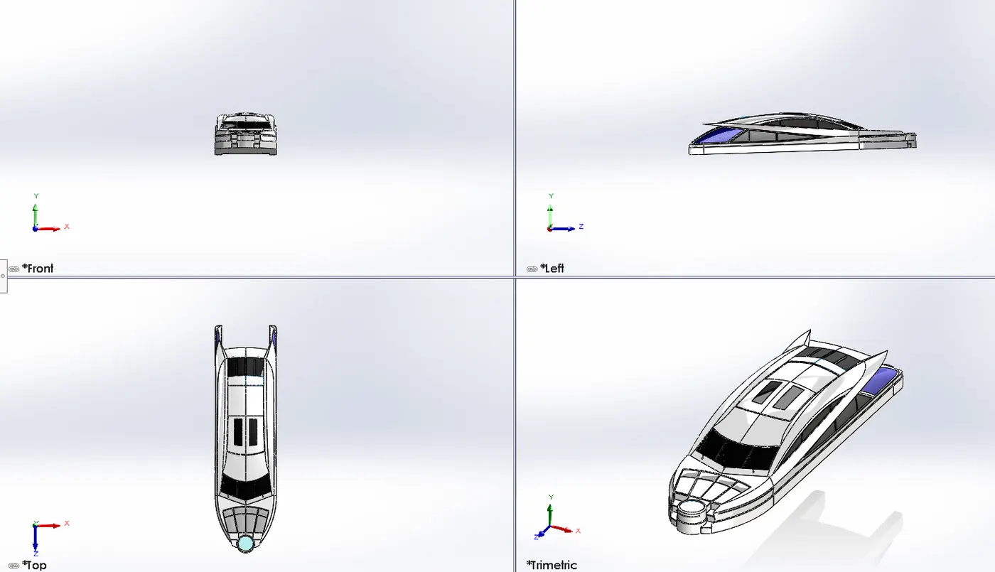
Final Assembly:
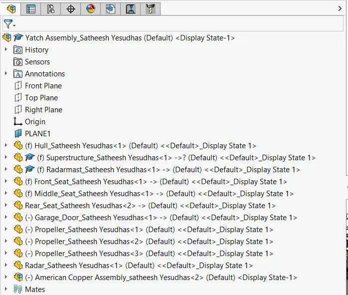
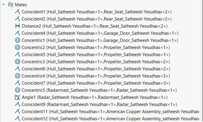
The above parts are designed individually and then assembled. The main purpose of the assembly of the Yacht is that assembly all individual parts with suitable mates.
Tree Structure of the assembly:
Mates used to assemble the Yacht:
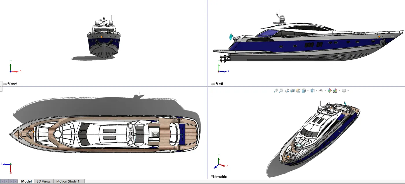
Rendering of the Chopper:
Render:
In 3-D graphic design, rendering is the process of adding shading, color, and lamination to a 2-D or 3-D wireframe to create life-like images on a screen. Rendering may be done ahead of time (pre-rendering) or it can be done on the fly in real-time.
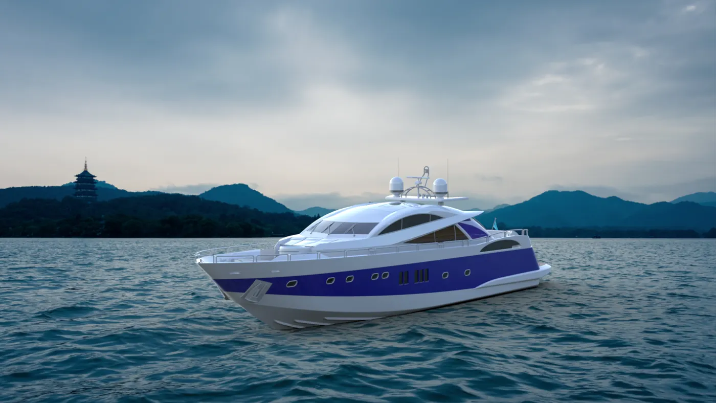
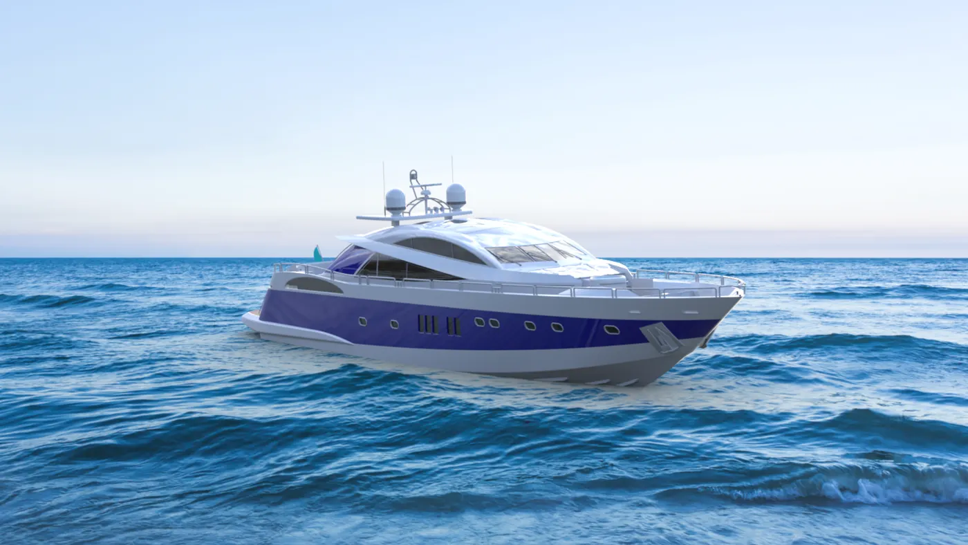
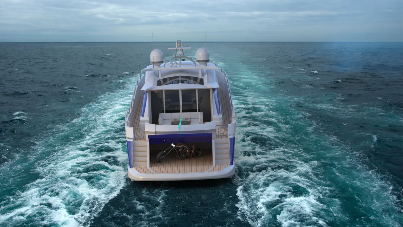
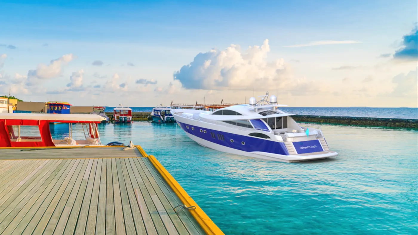
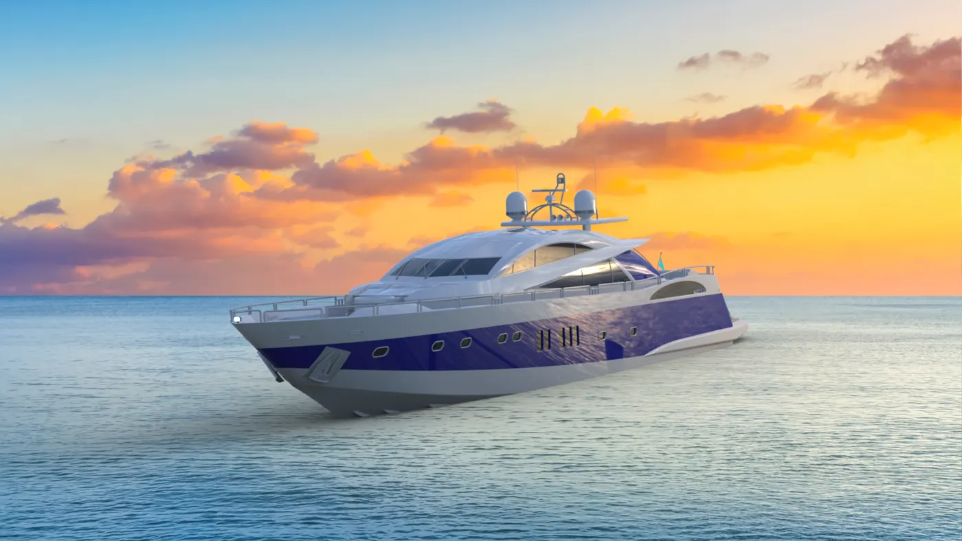
In this project., Solidworks Photo View 360 and Solidworks Visualize are used to render the final assembly part in different scenes.
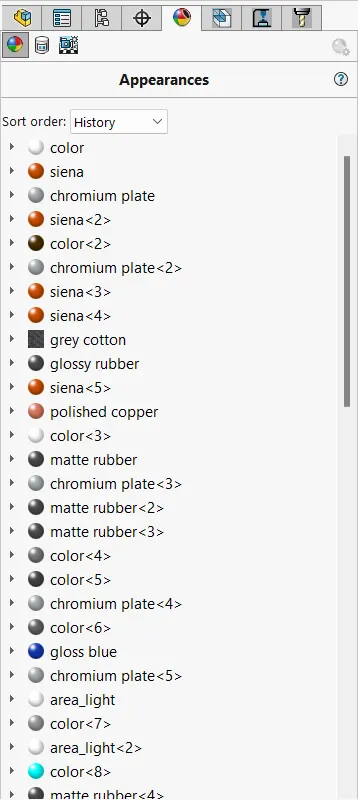
Appearance:
Appearance Design means the appearance presented by an object, formed in hardware or by software that creates a visual impression on an observer. Appearance Design refers to the ornamental and not the functional aspects of an object.
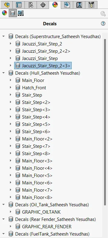
Decals:
Decal, also called Decalcomania, design that is printed on specially prepared paper to form a film that can be transferred to any surface. Such films are widely used for decorating and labeling any objects that cannot be run through a press. Decals are made in a variety of ways, depending upon the need to be served.
Scene, Light, and Camera:
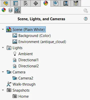
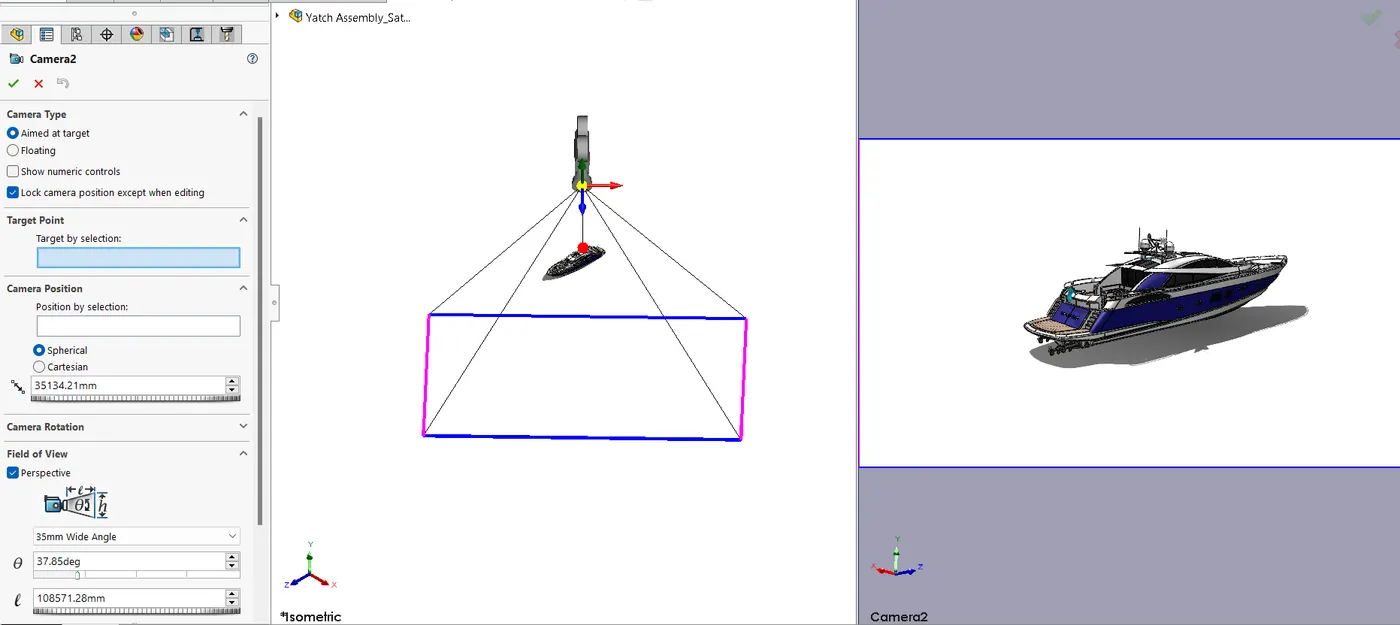
- The scene, lights, and Cameras play a major role in the rendering process, they decide the scene view and lighting.
- To set the scene first the background is set as plain white then the environment is set as daytime it also gives an adequate amount of light to the scene.
- Then the camera is set to give the most appropriate view of the Yacht.
Rendering in Photoview 360:
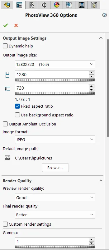
It is an add-in from the Solidworks software. By enabling photo view 360 we can render the final scene concerning the scene, lights, and camera view.
We can play with the options to get accurate render images.
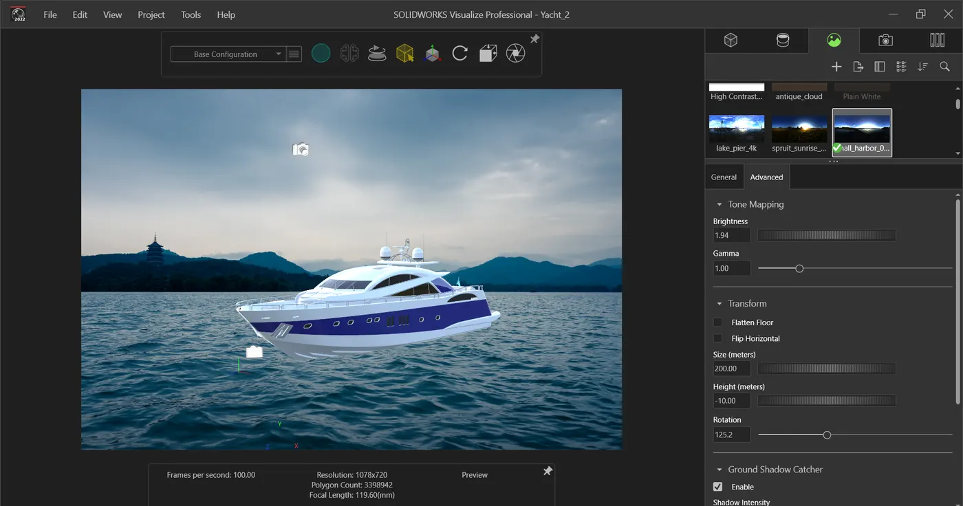
Rendering in Solid Works Visualize:
It is used to render the model with different hdri backgrounds We can also adjust the camera and lights to get an accurate view and lighting.
Final Rendered Images:
Conclusion:
Thus the modeling, assembling, and rendering of a Yacht were completed by using different commands in Solidworks and Solidworks Visualize.