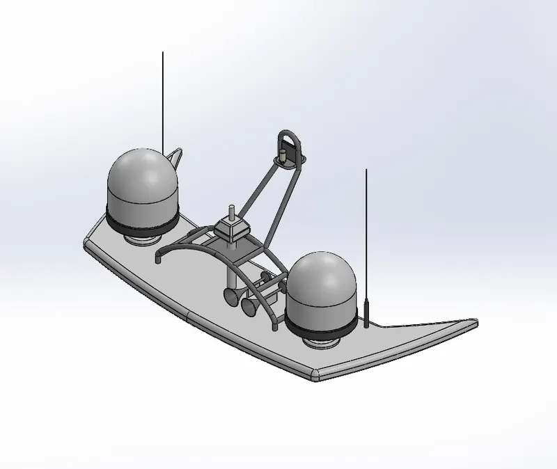
Radar Mast & Final Assembly of Yacht
Title : DESIGN, MODELING , RENDERING & ASSEMBLY OF SUNSEEKER YACHT
Objective:
Design all single parts or components and assembled them to build an Sunseeker Yacht.
Introduction:
In this project, we use sketching tools to draw the 2D model and using some features we can turn them to the 3D parts.
The main aim of this project is to learn how to use the surface tools.
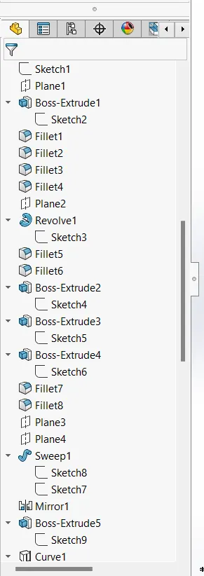
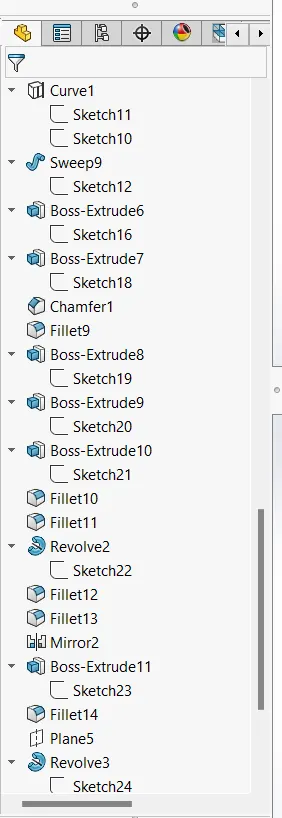
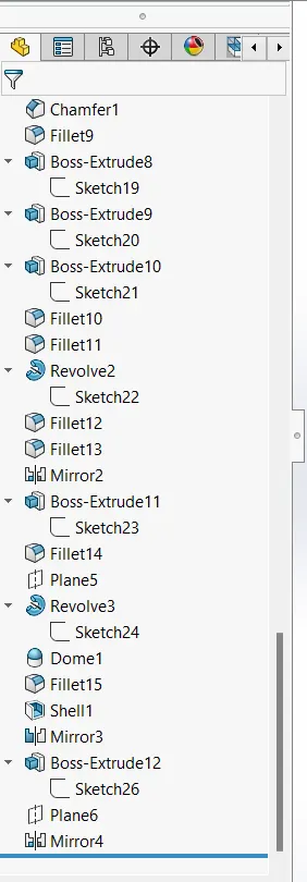
During this process we used some feature tools like Extrude Boss, Revolved Boss, Extrude Cut, Surface tools, Projected Curves, Split tools, Fillet, Chamfer etc.
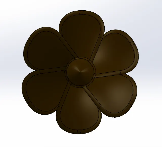
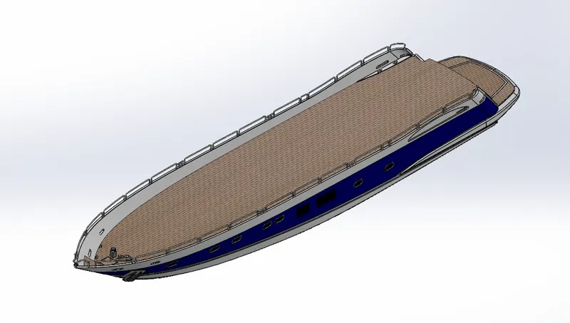
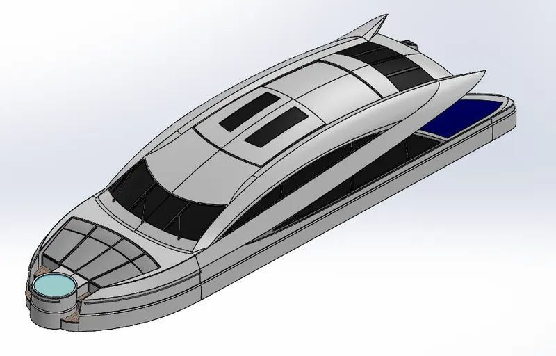
Parts of American Chopper:
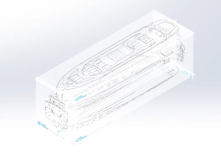
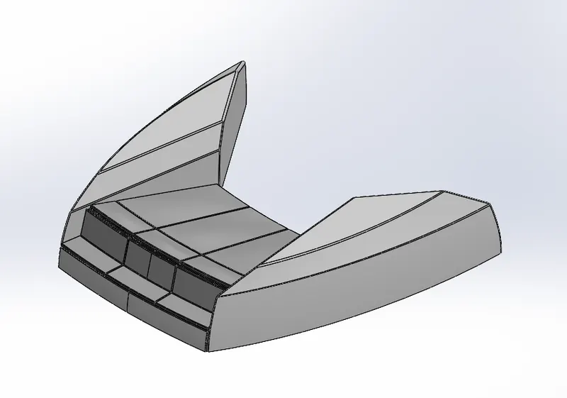
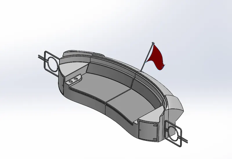
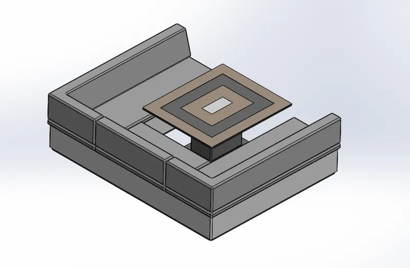

Design Methodology:
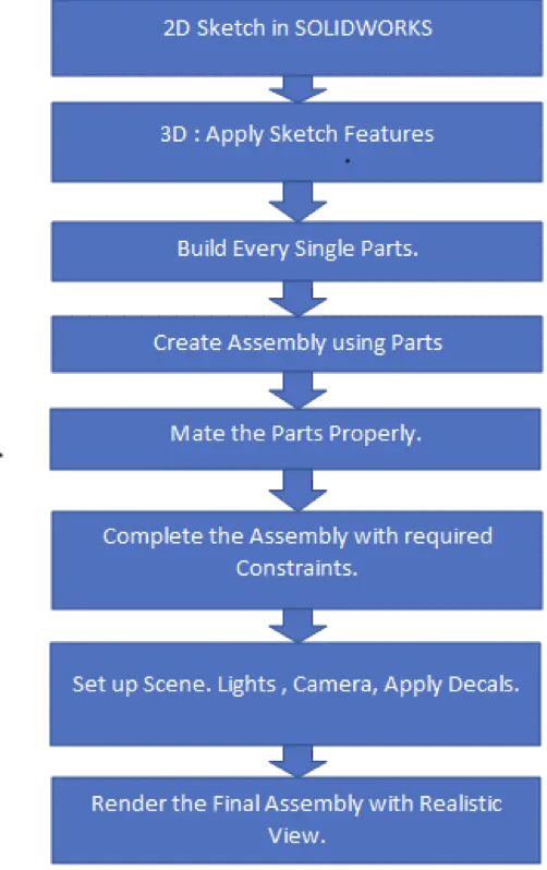
Description:
Key Features which are used to make Assembly.
2D Sketch makes it easier to seamlessly take concepts from the drawing/design phase to the drafting phase that fleshes out precise dimensions and scale.You can draw line, spline, circle, rectangle etc. according to your drawing.
In short, use a 3D sketch to create a path for tubing, sweeps, lofts, or surface edges, when the design continues to multiple planes.
The loft function in SolidWorks is a useful tool for (surface) modeling. The loft feature creates a shape by combining many profiles and guiding curves. This tool is quite useful for modeling complex surfaces.
In this feature by using surface boundary and selecting the edges we can patch or fill the surface.
This feature is use to extend the particular surface by selecting the edge.
In this we can trim the overlapping surface which is not required.
The Offset Surface tool creates a new surface body from an existing set of faces. The faces may be solid or surface faces.
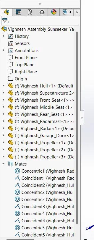
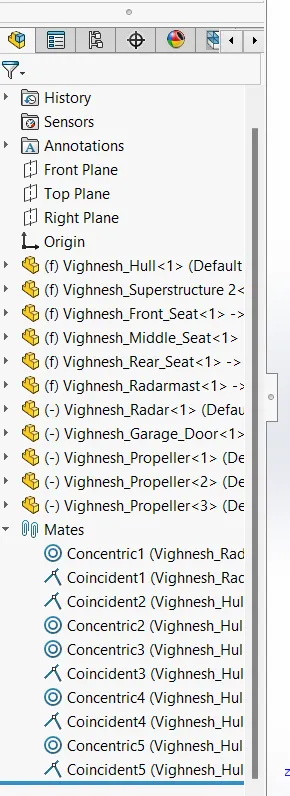
The important thing in assembly is to mate the parts perfectly by selecting planes and faces.
To design solid part, we must use this feature. It Extrude sketch or selected sketch counters in one or two dimension to create a solid feature
Extruded cut feature removes material from the part. You can cut in both directions mainly use for creating Holes, Channels and Slots.
Fillet/Chamfer a rounded internal or external face on the part. You can fillet all edges of a face, selected sets of faces, selected edges, or edge loops.
The shell tool hollows out a part, leaves open the faces you select, and creates thin-walled features on the remaining faces. If you do not select any face on the model, you can shell a solid part, creating a closed, hollow model. You can also shell a model using multiple thicknesses.
This feature is used to revolve a 2D sketch along an Axis or Centerline to create an 3D Sketch.
In symmetric assemblies, the right and left sides may use the same parts that are mirrors of each other. Instead of creating a new part and spending the time to model and detail the mirrored part file. To mirror a part, create a plane to mirror the part over the model or select a face. You can mirror any solid bodies and also Features.
Linear Pattern enables you to copy an existing feature and apply it in various ways, saving you time from having to recreate them
It is use to create a plane Parallel, Perpendicular, Coincident or angle to the selected plan or face etc. When you need to add additional material having a certain distance away from the earlier created part mode. Then the basic planes are not useful so to create another plan we can use ths tool.
Project curves are used to create a smooth curve between two points in a 3D space. They can be used for a variety of purposes, such as creating a swept surface or blending two surfaces together.
This tool is use to make the model more realistic by applying the color or material to the assembly parts.
Decals are images or logos that are projected on to your model. They could be something like a bar code, warning label or logo.
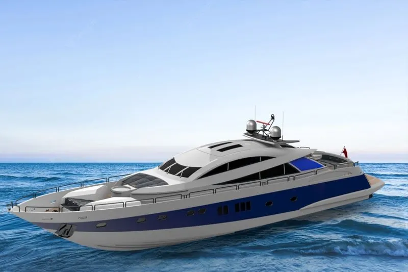
We can see this tool in SOLIDWORKS Visualize is a photo-realistic rendering tool that utilizes your Model to create magazine quality images or commercial quality animations.
It is use to Deletes a face from a surface body, or deletes one or more faces from a solid body to create surfaces.
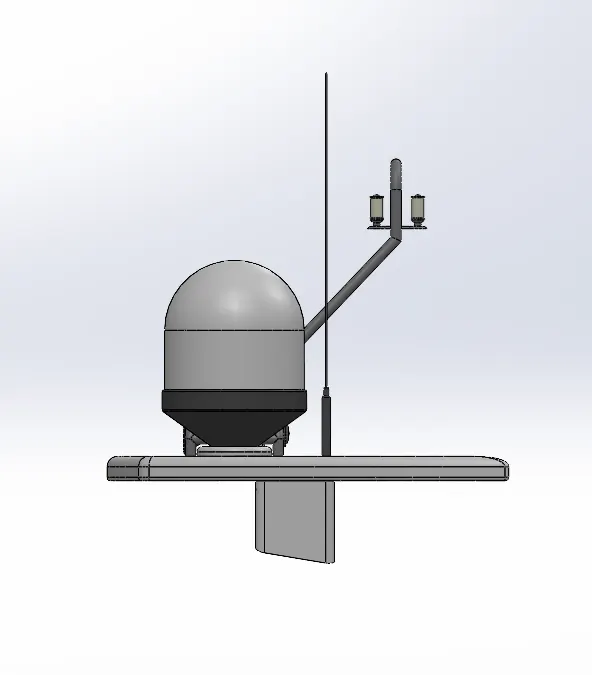
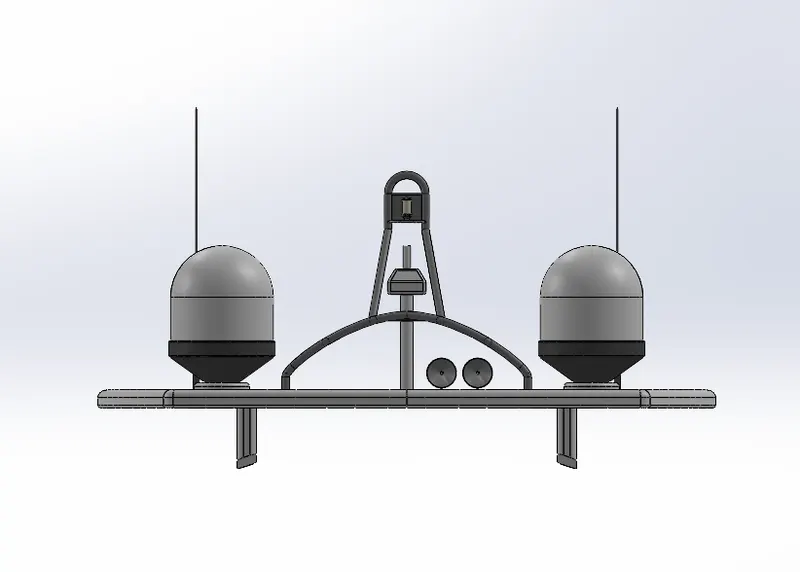
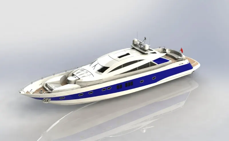
Final Assembly Views:
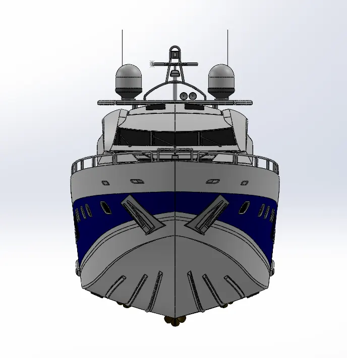
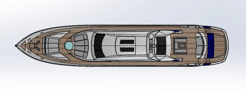
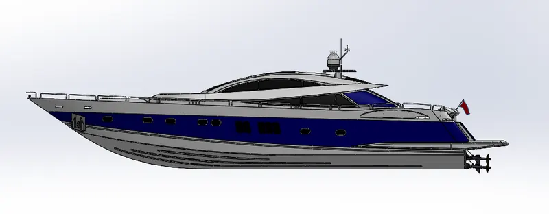
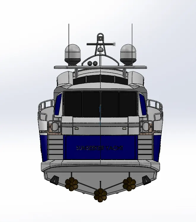
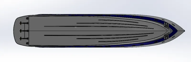
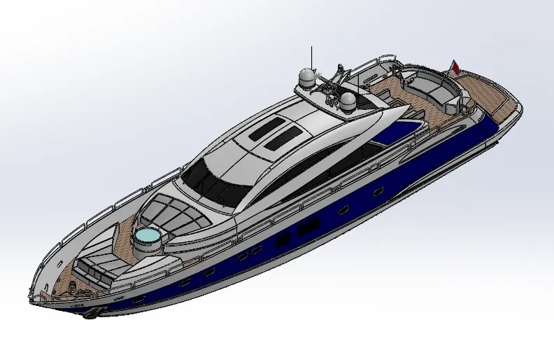
Photo View 360 (Render Feature):
SOLIDWORKS Visualization Views:
Conclusion:
Learn Basic to Advance Knowledge of SolidWorks.
Understand How to use Surface Features.
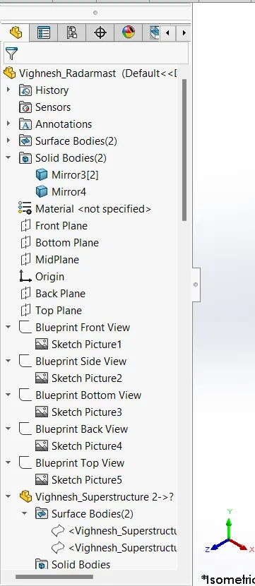
Understand how to use the Blueprint setup.
Learn how to assemble the model using the Mates.
How to give a realistic view to the model using Photo View 360 and SolidWorks Visualization.