Radar Mast & Final Assembly of Yacht
Radar-Mast
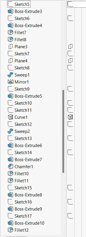
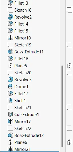
YACHT MODEL
INTRODUCTION :
A yacht is a sail or power vessel used for pleasure, cruising, or racing. There is no standard definition, so the term applies to such vessels that have a cabin with amenities that accommodate overnight use.These materials and others continue in use. Whereas yachts of 79 feet (24 m) and below may be constructed of fiberglass, larger yachts are more likely to be constructed of steel, aluminum or composite fiber-reinforced plastic.
DESCRIPTION :
Rendering of the individual parts was done in SolidWorks Visualize Professional '19. The Real View graphics were enabled for efficient rendering.
Setting up the Blueprints :
All the blueprints were imported into a SolidWorks part file using the path : Tools - Sketch Tools - Sketch Picture.This Blueprint setup is then used to model all the parts.
Modelling the Propeller :
A Propeller is a device with a rotating hub and radiating blades that are set at a pitch to form a helical spiral, that, when rotated, performs an action which is similar to Archimedes' screw.It transforms rotational power into linear thrust by acting upon a working fluid, such as water or air.The propeller is modelled simply by using solid modelling features suh as - Revolved Boss/Base, Extruded Cut, etc.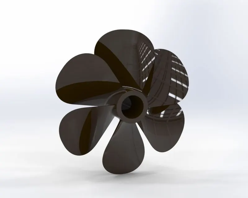
Modelling the Radar :
Marine Radars are X band or S band radars on ships, used to detect other ships and land obstacles, to provide bearing and distance for collision avoidance and navigation at sea.
They are electronic navigation instruments that use a rotating antenna to sweep a narrow beam of microwaves around the water surface surrounding the ship to the horizon, detecting targets by microwaves reflected from them, generating a picture of the ship's surroundings on a display screen.
Modelling the Yacht Hull and the Garage door :
A Hull is the watertight body of a ship or boat. The hull may open at the top (such as a dinghy), or it may be fully or partially covered with a deck.Atop the deck may be a deckhouse and other superstructures, such as a funnel, derrick, or mast. The line where the hull meets the water surface is called the waterline.Here, the hull is essentially modelled by Surface Modelling.The railing is modelled by creating projected curves through different sketch tools and then by using the Swept Boss/Base command with the curves as the sweep path.Fillet is used at all the required places where sharp edges are to be avoided. Also, providing fillets around the windows gives a good aesthetic appeal to the model.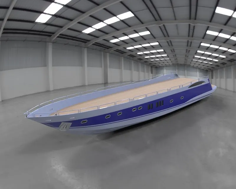
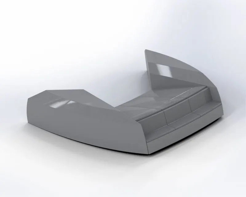
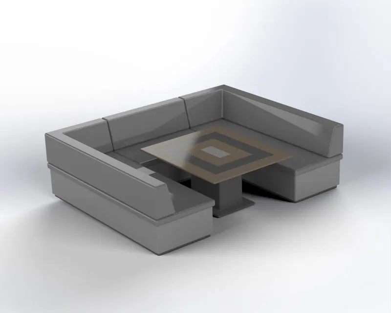
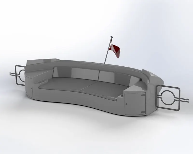
Modelling the Seats :
Seats are modelled either by solid features or by using surface features.There are three seatings in the model - Front, Middle and Rear.
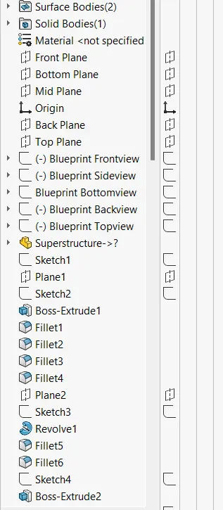
Modelling the Superstructure :
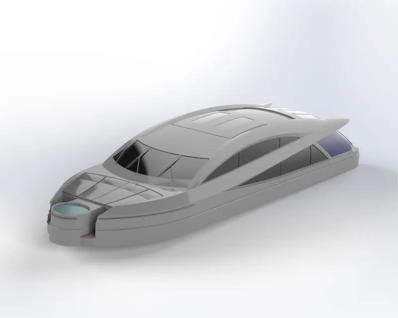
On water craft, the superstructure consists of the parts of the ship or a boat, including sailboats, fishing boats, passenger ships, and submarines, that project above her main deck.This does not usually include its masts or any armament turrets.Here, the Superstructure is also modelled by creating the outer surfaces first, just as we did in the case of Hull.
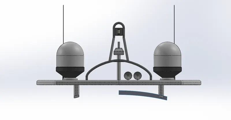
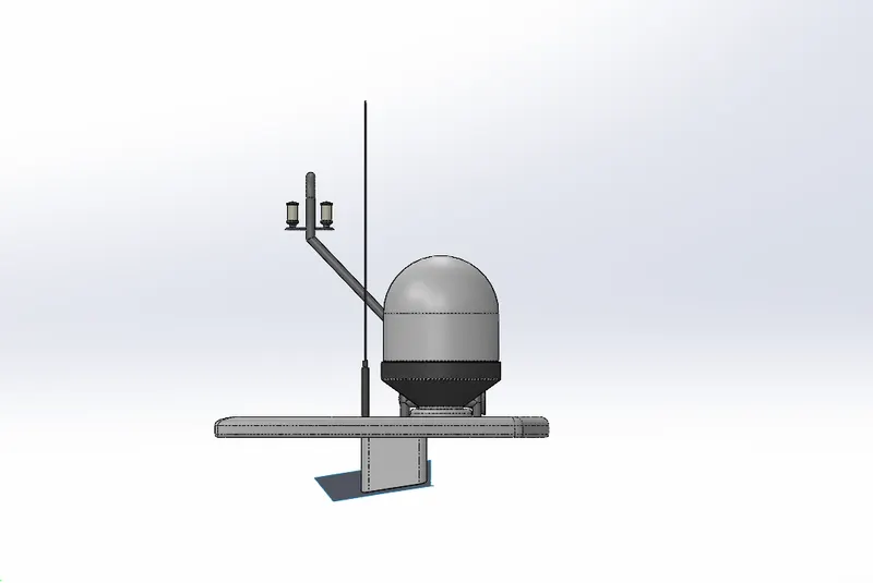
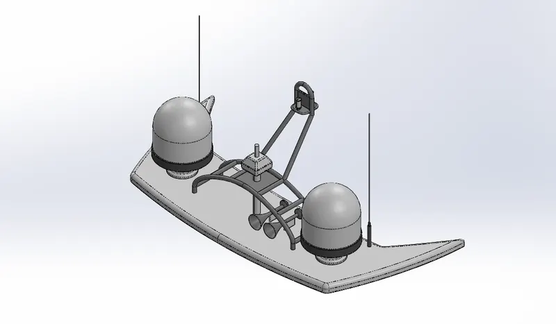
Modelling the Radar Mast :
The Mast of a sailing vessel is a tall spar, or arrangement of spars, erected more or less vertically on the centre-line of a ship or boat.Its purposes include carrying sails, spars, and derricks, and giving necessary height to a navigation light, look-out position, signal yard, control position, radio aerial or signal lamp. The horns are modelled by using the Shell feature. This feature essentially removes off the inside material out of a solid 3D part, thereby making it hollow.The Mirror feature is used to mirror symmetric entities.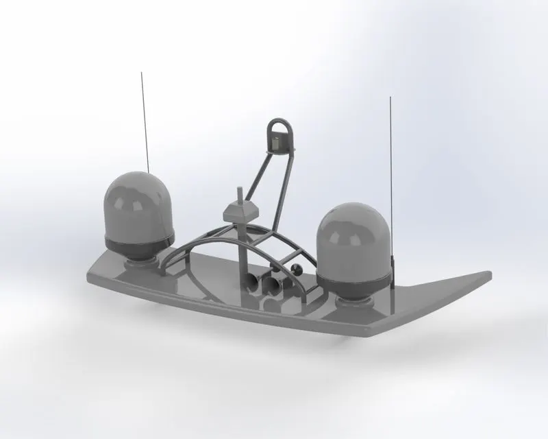
Creating the Assembly :
All these individual parts are then assembled together using the SolidWorks Assembly file.First off, the Hull is fixed at the proper location.Rest all the parts are then located with respect to this fixed Hull.Standard Mates such as Coincident, Tangent, Concentric, Parallel, etc are used to provide appropriate constraints.
Rendering :
Available Decals are added to enhance the outlook of few of the parts.The Yacht Assembly is rendered using the Add-In SolidWorks Visualize tool provided by SolidWorks.Proper Scene is created for the rendering.Appropriate Environment is set up for this purpose. Also, a suitable Backplate is chosen out of the library.Camera is set up by providing appropriate location.The Perspective view is enabled to ensure real-time look.Now, after providing suitable appearances the model is rendered.
CONCLUSION :
Thus, the complete exterior body parts of a Sunseeker Predator Yacht are modelled in SolidWorks Part file, assembled in SolidWorks Assembly file and then the assembly is rendered using SolidWorks Visualize.