Photo Realistic Rendering
AMERICAN CHOPPER
OBJECTIVE :
To create modelling and photo realistic rendering of
American chopper using by solidworks.
INTRODUCTION:
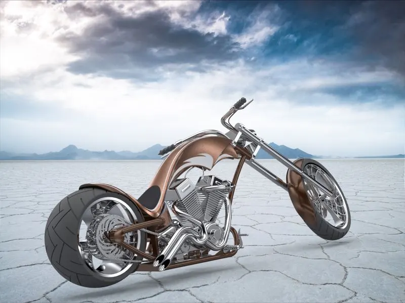
In this project I had built an American chopper. The designing
started with ideation process followed by part modelling one by one for
each part. After that parts are assembled in assembly environment and
then rendered using SOLIDWORKS visualize.
METHODOLOGY:
MODELLING:
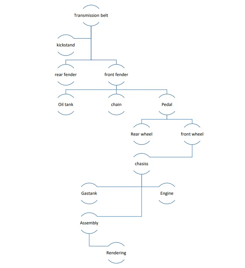
The chopper contains parts are following below
Transmission belt
rear fender front fender
Oil tank chain Pedal
Rear wheel front wheel
chasiss
Gastank Engine
Assembly
Rendering
kickstand
MODELLING:
The chopper contains parts are following below
1.Transmission belt
2.Kickstand
3.Rear fender
4.Front fender
5.Chain
6.Pedal
7.Oil Tank
8.Front Wheel
9.Rear Wheel
10.Front Fork
11.Chasis
12.Engine
13.Gas Tank
All these parts are sepertely designed and finally
assembled the American chopper
WEEK 1:
Parts: Transmission belt, kickstand, Frontfender, Rearfender
Command’s used:
2d sketch
Lines and circles
Extrude
revolve
Dome
Fillet
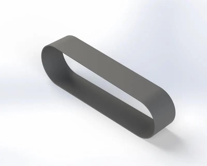
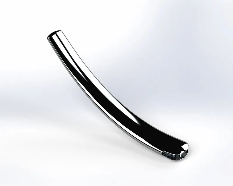
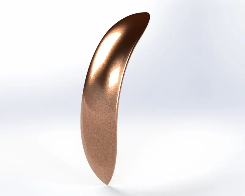
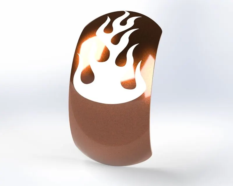
The above following commands are used to design to make the week 1 parts.With
help of week1 videos to get the dimension and the follow instruction.
Week2:
PARTS: Oil tank, Chain, Pedal
Command’s used:
2d sketch
Sweep
Revolve
splines
Trim
Extrude cut
Fillet
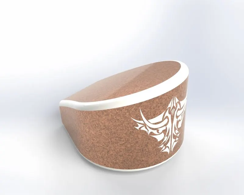
In this oil tank we create the solid body and cobine the two bodies into a single
body by using combine feature.
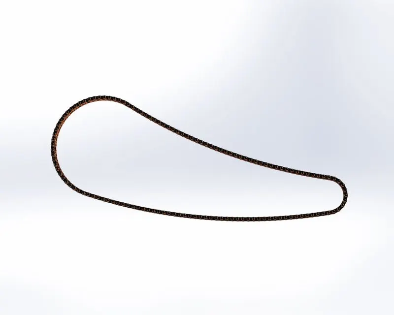
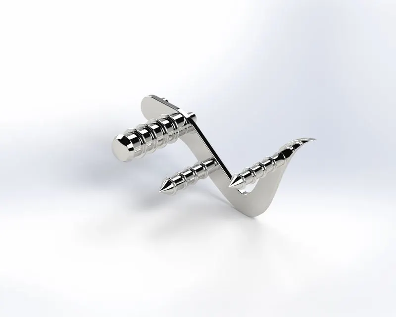
To make the twonew block inside the drawing while creating chain part.
The above following commands are used to design to make the week 2parts.With
help of week 2 videos to get the dimension and follow instruction.
Week3:
PARTS:Front wheel
Command’s used:
2d sketch
Sweep
Revolve cut
Circular pattern
combine
Extrude cut
Revolve
Fillet
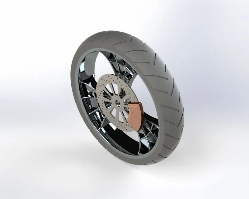
In Front wheel we are using circular pattern for making that spider web rim.
Revolve cut also used for the rim to get better surface finish.
The above following commands are used to design to make the week 3 parts.and
the dimensions and instructions are followed by the week 3 video.
Week4:
PARTS:8.Rear wheel 9.Front fork
Command’s used:
3d sketch
Sweep
Revolve
Mirror pattern
Dome
Projected curve
Combine
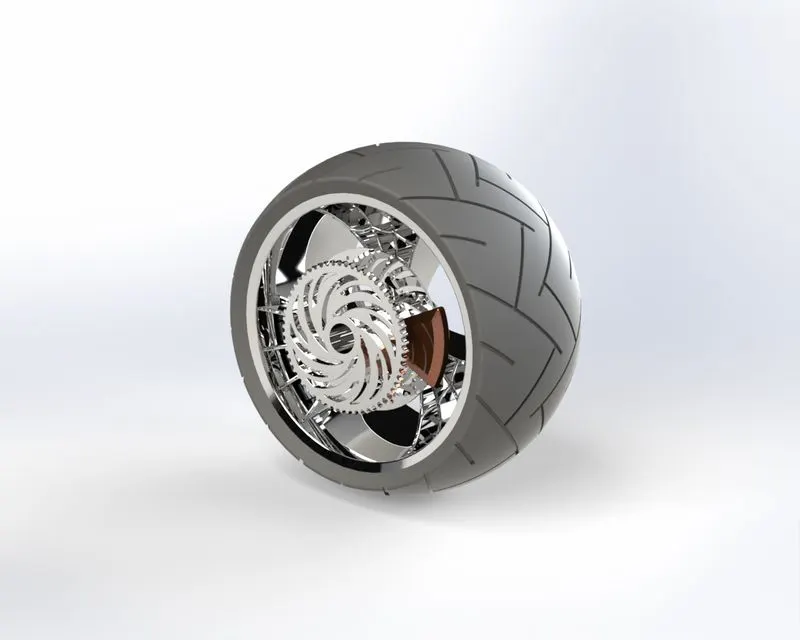
The rear wheel is as same as the front wheel chain sprocket is the additional part
we have to design in the rear wheel.
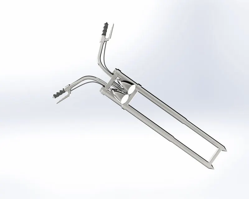
In this fork we used projected curve and sweep to get the handle in the fork.used
the mirror feature to be make another side of fork to complete.
The above following commands are used to design to make the week 4 parts.
With help of week 4 videos to get the dimension and follow instruction.
Week5:
PARTS: Chassis,engine
Command’s used:
Sweep
Revolve
Extrude
Dome
Projected curve
Split
Mirror
Fillet
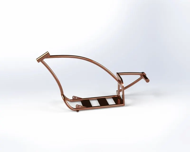
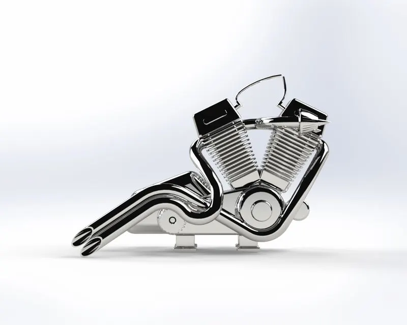
The projected curves are used to make the engine exhaust, most of the solid
modelling features are used to finish the engine.
The above following commands are used to design to make the week 5 parts.
With help of week 5 videos to get the dimension and follow instruction.
Week6:
PARTS: Gas tank
Command’s used:
*Surface loft
*Surface Sweep
*Boundary surface
*Revolve
*Extrude
*Knit surface
*Projected curve
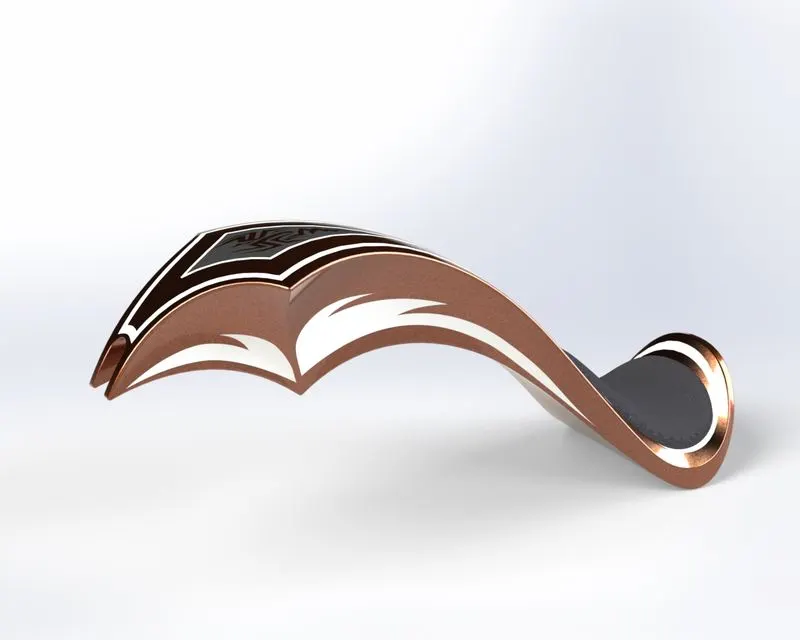
In this gas tank we used surface and modeling tools are used to get a better finish.
The above following commands are used to design to make the week 6 parts.
With help of week 6 videos to get the dimension and follow instruction.
After the making the all parts and we give the appearance to each part for the
good look.
ASSEMBLY OF AMERICAN CHOPPER:
To make the assembly of American chopper we have to use some of the mates.
They are following below
concentric mate
Parallel mate
Angle mate
Distance mate
Advance mate
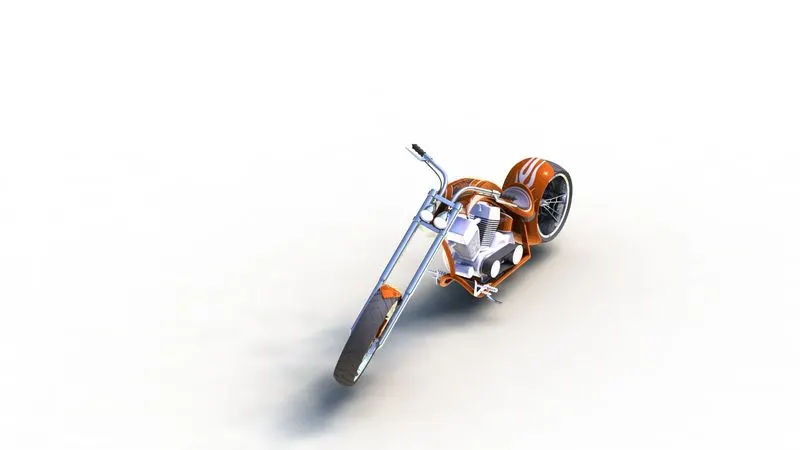
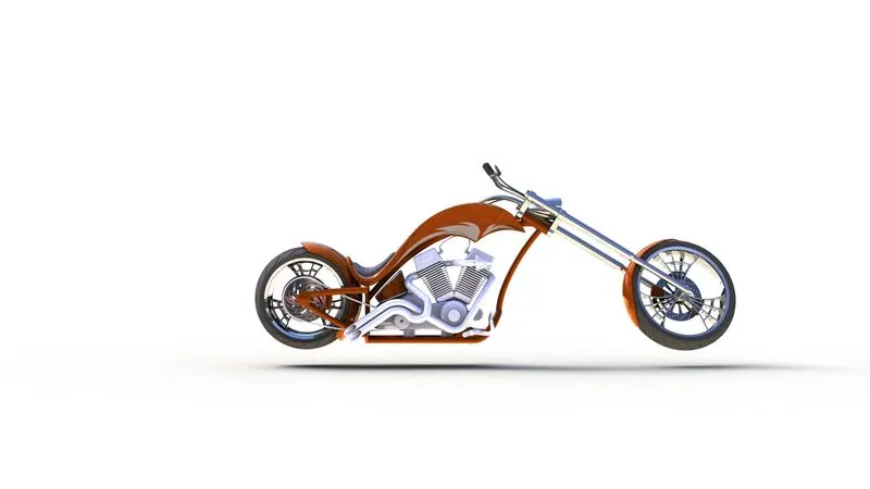
PHOTOVIEW360 RENDERING
To make the chopper more realistic to use the photoview360 .
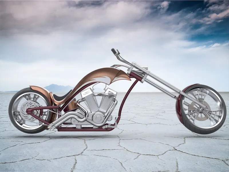
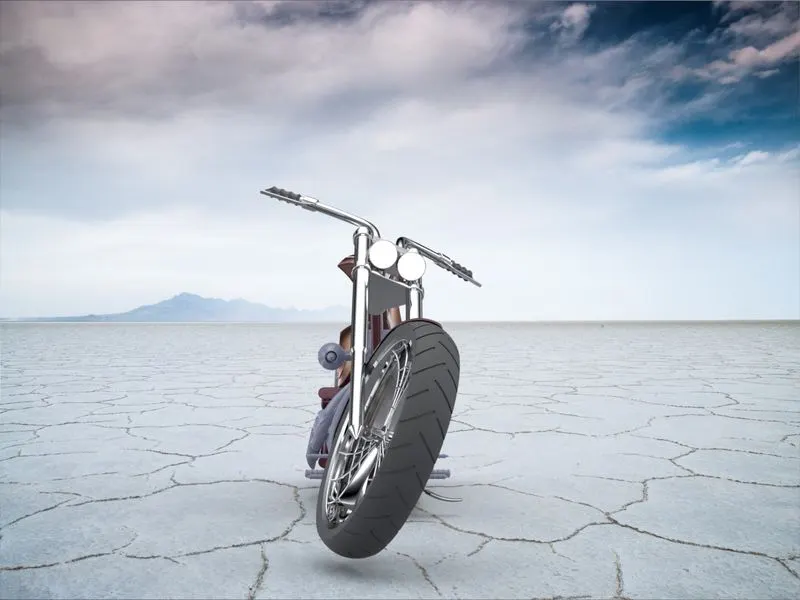
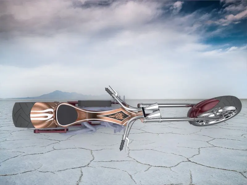
SOLIDWORKS VISUALISE:
Solidworks visualise is used to render the American chopper, and the
help of some tools of the visualize and background setting is given pretty
realistic look of the American chopper.
CONCLUSION:
Modelling, assembly and rendering of an American chopper is
successfully done by solidworks.
Regards by,
Surendhar G