Radar Mast & Final Assembly of Yacht
MODELLING OF YACHT USING SOLIDWORKS
INTRODUCTION
A yacht is a watercraft used for pleasure or sports. Today's yachts are almost exclusively for leisure. A yacht is any sail or power vessel used for pleasure, cruising, or racing. Until the 1950s, almost all yachts were made of wood or steel, but a much wider range of materials is used today. Although wood hulls are still in production, the most common construction material is fibreglass, followed by aluminium, steel, carbon fibre, and ferrocement. Apart from materials like carbon fibre and aramid fibre, spruce veneers laminated with epoxy resins have the best weight-to-strength ratios of all boatbuilding materials.
In recent years, these yachts have evolved from fairly simple vessels with basic accommodation into sophisticated and luxurious boats. This is largely due to reduced hull-building costs brought about by the introduction of fibreglass hulls, and increased automation and "production line" techniques for yacht building. Most basic yachts have electric lighting, radio and navigation aids such as GPS. Aids such as radar, echo-sounding and autopilot are common.
OBJECTIVE
- The main objective is to create a 3 dimensional modal of Yacht using different modules Like Sketch, Feature, Surfacing, Evaluate, etc.
- How to assemble different components of Yacht with the help of mates.
- Knowledge of Decals, Light, Cameras, etc. in a modal.
- How to create a render of a real 3-dimensional modal using Photo 360 and Solidworks Visualize.
Part Modeling :
- Part Modeling you can create a part from a conceptual sketch through solid feature-based modeling, as well as build and modify parts through direct and intuitive graphical manipulation.
Surface Modeling :
- Surface modeling gives you the ability to build out a visual representation of an object’s exterior and its contours. In other words, it’s a surface.
- Surface modeling plays a major role in modeling a yacht. Most of the parts in the yacht are surface modeled.
- The following are the features used in surface modeling.
Parts to model:
- Yacht Blue Print
- Propeller
- Radar
- Hull tutorial
- Garage door
- Front seat
- Middle seat
- Rear seat
- Superstructure
- Radar mast
- Assembly tutorial
DESIGN METHODOLOGY/APPROACH:
DESCRIPTION:
To Create Different components of Yacht
In this module, we designed different components of Yacht as per the given dimension then save the (.prt) file.
1. Yacht Blue Print
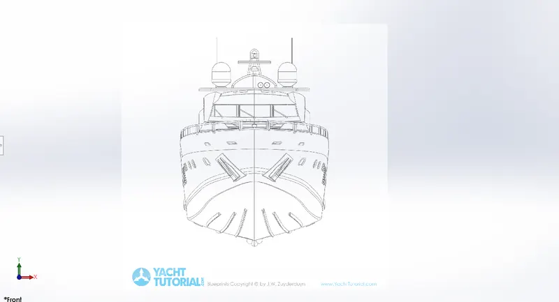
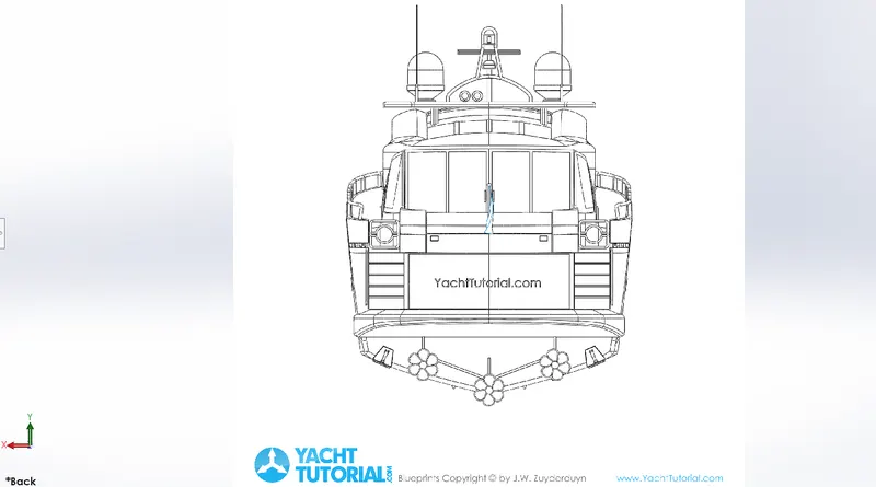
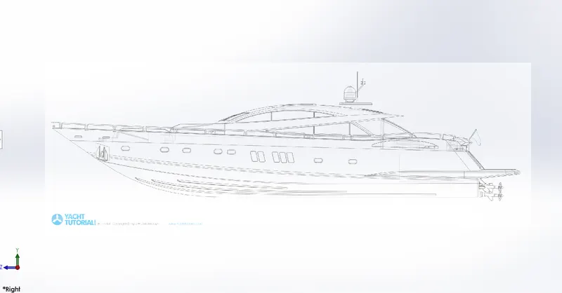
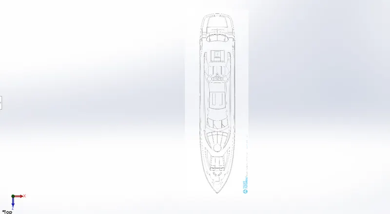
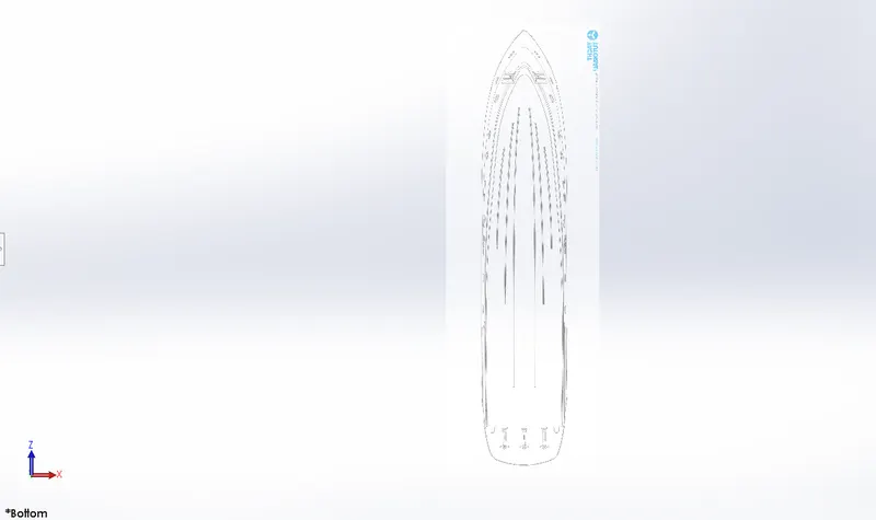
A blueprint is a guide for making something or it's a design or pattern that can be followed. Yacht blueprint is a combination of multiple images of the yacht, such as front view, top view, side view, bottom view and back view. Blueprint of the yacht is used for guidance while designing individual parts of the yacht.
Procedure for modelling Yacht blueprint in brief.
- Open a new part and create a blueprint of the yacht.
- In a new sketch, import the image of the top view of the yacht and place it at an appropriate position with respect to the origin.
- Repeat the previous step to all the views such as- Front view, Side view, Bottom view and Back view.
- Save the file as the blueprint of the yacht.
- Rendered image of the yacht blueprint is shown below.
2. Yacht Propeller
A propeller is a type of fan that transmits power by converting rotational motion into thrust.
- A pressure difference is produced between the forward and rear surfaces of the airfoil-shaped blades, and a fluid (such as air or water) is accelerated by the pressure difference.
- Most marine propellers are screw propellers with helical blades rotating around an approximately horizontal axis or propeller shaft.
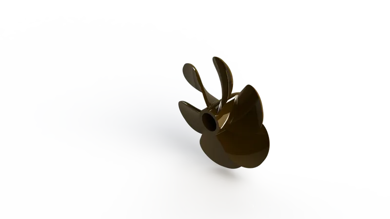
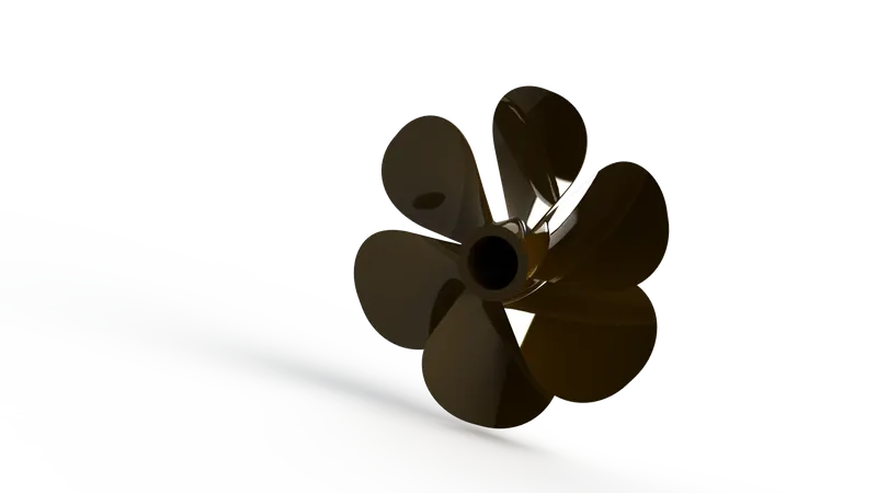
- Six blades are used on the propeller used in this model.
Features used to create Propeller
- Sketch
- Revolve
- Cut Extrude
- Loft
- Fillet
- Circular Pattern
Sketch:- Sketch is the two dimensional representation of the model with respect to the plane/view from the outside of the mode.
Revolve:- To create a revolve feature: Create a sketch that contains one or more profiles and a centerline, line, or edge to use as the axis around which the feature revolves.
Circular Pattern:- Circular pattern is used to create a pattern of the propeller. By using this multiple patterns are created.
Loft:- Loft feature is used to complex 3-D models between non-similar cross-section shapes.
Fillet:- Fillet is used to convert sharp edges to round.
Extrude Cut:- This is used to remove material from the solid with help of a sketch.
Procedure for modelling Yacht propeller in brief.
- Insert the blueprint of the yacht in a new part.
- Create the centre shaft of the propeller.
- Create one propeller blade and provide fillets to all the necessary edges.
- Create a circular pattern of the propeller blade throughout the shaft at equal distance.
- Apply colour to the surface of the propeller.
- Rendered images of the yacht propeller are shown below.
3. Radar
Radar is a detection system that uses radio waves to determine the range, angle, or velocity of objects. It is used generally in aircraft, ship, spacecraft, missiles, weather formations etc. The radar consists of a transmitter, antenna for transmission, receiver and processor. The transmitter transmits a signal to the surroundings which are reflected back if there are any obstacles in its path. The reflected signal is received by the receiver and processed by the processor to find the type, size and distance of the obstacles.
- The radar used for the marine purpose is usually called as marine radars.
- It is used to detect other ships and land obstacles, to provide bearing and distance for collision avoidance and navigation at sea.
- Rotating antenna is used for wide coverage while the ship is in motion.
Features used to create Radar
- Sketch
- Extrude Boss
- Fillet
- Extrude Cut
- Sketch Pattern
- Mirror
- Split Line
Extrude Boss:- Extrude feature is used to create a 3-D model from a 2-D sketch.
Mirror:- It is used to mirror the sketched entities or bodies.
Split:- This is used to divide into planar or curved surfaces.
Procedure for modelling Yacht radar in brief.
- Insert the blueprint of the yacht in a new part.
- Create the side view of the radar and extrude it.
- Provide fillet to all the sharp edges.
- Create the cap and fasteners on the side of the radar.
- Create the remaining part of the radar by mirroring the hull modelled till the last step.
- Apply decals and appearance on the surface of the radar.
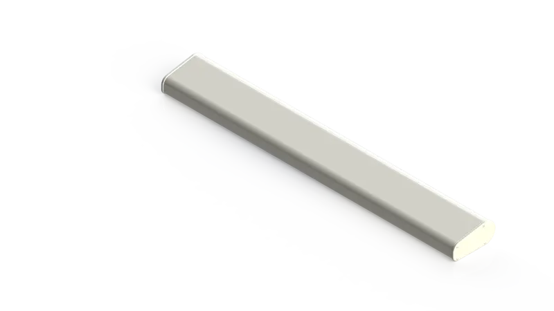
- Rendered images of the yacht radar are shown below.
4. Hull
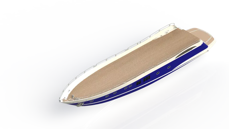
A hull is the major part of a ship or boat or yacht which is watertight in nature. It may be open at the top or may be fully or partially covered. Over the hull, there may be deckhouse, front seat, middle seat, back seat, mast, cabin etc. The line where the hull meets the water surface is called the waterline. A wooden floor is provided in the hull. Previously wood was used for constructing hull and nowadays most common construction material is fibreglass, followed by aluminium, steel, carbon fibre, and Ferro cement.
Features used to create Hull
- Sketch
- Projected Curve
- Surface Loft
- Surface Trim
- Surface Extrude
- Surface Fill
- Surface Knit
- Extrude Boss
- Extrude Cut
- Fillet
- Chamfer
- Sweep
- Helix / Spiral
- Linear Pattern
- Delete Face
- 3D Sketch
- Mirror
- Split Line
- Offset Surface
Projected Curve:- It is used to create a 3-D curve from two 2-D curves or lines.
Surface Loft:- It is generated with the help of a 3-D curve or edge between two same or different cross-sections.
Surface Trim:- It is used to remove any extended surface with reference to any plane or surface.
Surface Extrude:- It is used to create a surface of uniform cross-section.
Surface Fill:- It is used to fill any surface by curves or lines at different positions.
Surface Knit:- It is used to knit the surface and removing the gap between them.
Chamfer:- Chamfer is used to remove the sharp edge or corner. It converts a sharp edge or corner into a tapered edge.
Sweep:- It is used to create a 3-D profile or same cross-section along with any 2-D sketch.
Helix / Spiral:- It is used to create a helical shape like spring.
Delete Face:- It is used to delete a surface and if required to remove the gap between surfaces we can use the delete and tangent fill options.
3D Sketch:- It is used to create a 3-Dimensional sketch.
Offset Surface:- It is used to create a 3-D surface offset from the main surface.
Procedure for modelling Yacht hull in brief.
- Insert the blueprint of the yacht in a new part.
- Create projected curves of the bottom part of the hull as per blueprint and create lofted surfaces.
- Create a lofted surface for the remaining bottom parts as per the blueprint.
- Trim unwanted surfaces for making the surfaces of the hull.
- Fill the open surface and knit all the surfaces.
- Create a shell of required thickness from the knitted surfaces.
- Create the deck surface by extruding.
- Create the basement by extruding.
- Remove unwanted portions from the hull model and provide fillet and chamfer to required edges.
- Create windows and portholes on the surface of the hull.
- Create stairs on the backside (one side) of the hull.
- Create long slots on the bottom surface of the hull.
- Provide fillet and chamfer to all the required edges.
- Create an anchor cable holder on the front side of the hull.
- Create windows on the surface of the hull.
- Create rail on the top of the hull.
- Create headlight on the front side of the hull.
- Create a shaft for the turbine on the bottom backside of the hull.
- Create a standing board on the front side of the hull.
- Create the remaining part of the hull by mirroring the hull modelled till the last step.
- Apply decals and appearance on the surfaces of the hull.
- Rendered images of the yacht hull are shown below.
5. Garage Door
The garage door body was 'Split' from the hull and imported separately for modelling. The garage door was mated with the hull garage during the assembly.
Features used to create Garage Door
- Sketch
- Extrude Cut
- Shell
- Fillet
- Mirror
Shell:- This feature is used to making any component hollow. We can remove any face if needed.
Procedure for modelling Yacht garage door in brief.
- Insert the blueprint of the yacht in a new part.
- Insert a block from the hull, which is removed from the hull for creating a garage for parking of a private vehicle in the hull.
- Remove all the unwanted portion of the block inserted and provide fillet on all the required edges.
- Create the remaining part of the garage door by mirroring the garage door modelled till the last step.
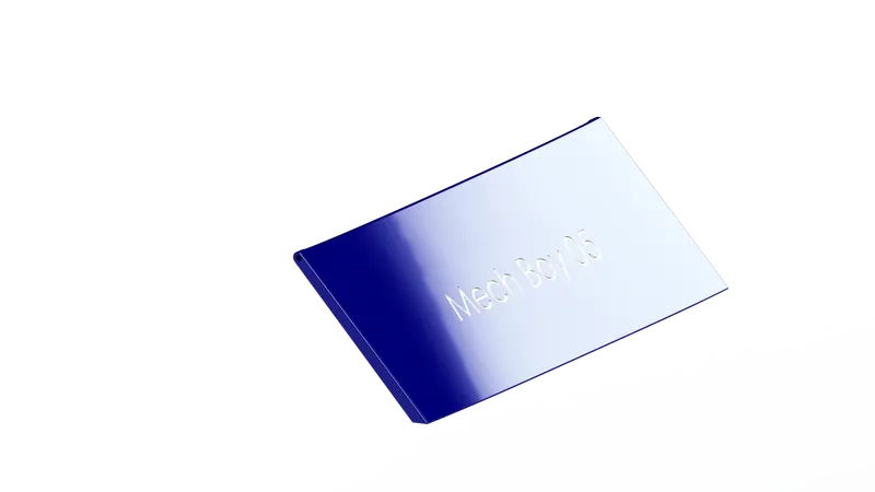
- Create the name of the yacht on the surface of the garage door.
- Apply colour to the surface of the door.
- Rendered images of the yacht garage door are shown below.
-
Procedure for modelling Yacht garage door in brief.
- Insert the blueprint of the yacht in a new part.
- Insert a block from the hull, which is removed from the hull for creating a garage for parking of a private vehicle in the hull.
- Remove all the unwanted portion of the block inserted and provide fillet on all the required edges.
- Create the remaining part of the garage door by mirroring the garage door modelled till the last step.
- Create the name of the yacht on the surface of the garage door.
- Apply colour to the surface of the door.
- Rendered images of the yacht garage door are shown below.
6. Front Seat
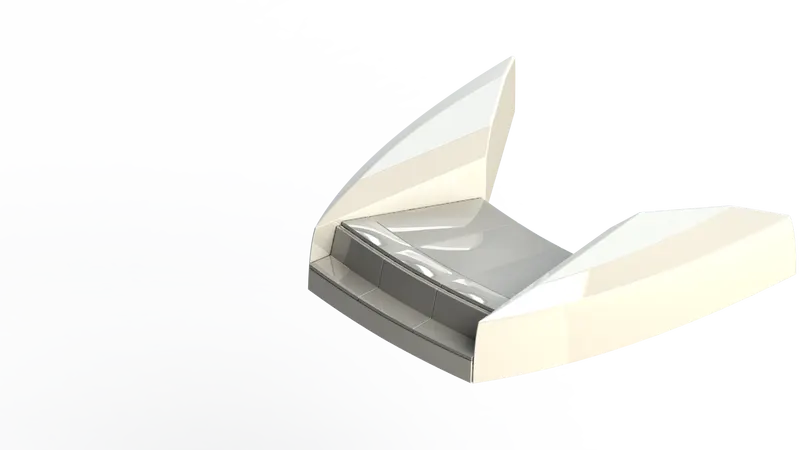
Front Seat is placed on the front part of the Hull.
Features used to create Front Seat
- Sketch
- Surface Sweep
- Surface Trim
- Surface Loft
- Surface Knit
- Surface Fill
- Revolve
- Extrude Cut
- Chamfer
- Extrude Cut Thin
- Dome
- Mirror
Surface Sweep:- It is used to create a 3-D surface or the same cross-section along with any 2-D sketch.
Extrude Cut Thin:- It is used to create a 3-D component of uniform thickness along with a sketch.
Dome:- Dome feature is used to creating a solid while pulling the centroid outward from the solid. In Dome, feature centroid comes outward while edges remain stick on that edge.
Procedure for modelling Yacht Front seat in brief.
- Insert the blueprint of the yacht in a new part.
- Create a projected portion in the side of the front seat of the yacht on the floor of the hull using surface modelling.
- Create the seating portion of the front seat.
- Provide fillet and chamfer to all the required edges.
- Create additional cushion on the surface of the seat.
- Provide fillet and chamfer to all the required edges.
- Create the remaining part of the front seat by mirroring the seat modelled till the last step.
- Apply appropriate colours to all the required surfaces.
- Rendered images of the yacht front seat are shown below.
7. Middle Seat
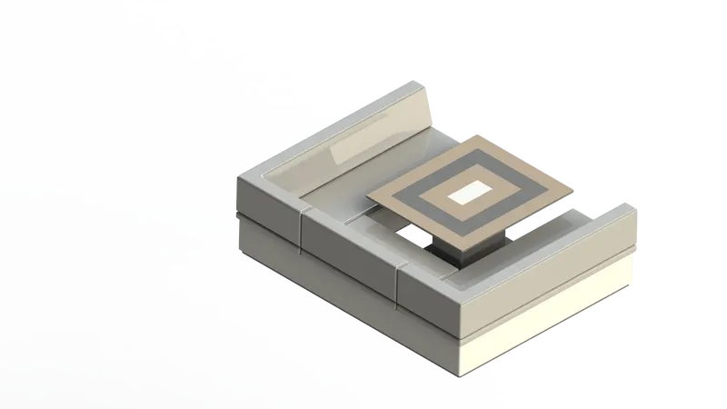
Middle seat is placed under the superstructure.
Features used to create Middle Seat
- Sketch
- Extrude Boss
- Chamfer
- Fillet
- Mirror
- Extrude Cut
Procedure for modelling Yacht Middle seat in brief.
- Insert the blueprint of the yacht in a new part.
- Create the base of the middle seat.
- Create the seating portion above the base of the seat.
- Create the cushioning part of the seat above the seating portion.
- Provide fillet and chamfer to all the required edges.
- Create the remaining part of the middle seat by mirroring the seat modelled till the last step.
- Create table at the centre of the middle seat.
- Apply colour to all the required surfaces.
- Rendered images of the yacht middle seat are shown below.
8. Rear Seat
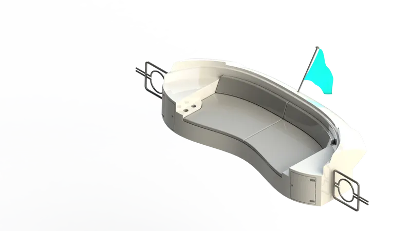
- Rear seat was placed over the garage behind the Superstructure. It was designed after importing the deck surface of the Hull as interface surface.
- The rear seat includes some parts like railing or gates which separates the upper deck and it also includes rear light and a flag and pole, and some small compartment/almirahs.
Features used to create Rear Seat
- Sketch
- Surface Sweep
- Surface Offset
- Surface Trim
- Ruled Surface
- Surface Knit
- Surface Extend
- Surface Loft
- Boss Extrude
- Cut Extrude
- Chamfer
- Fillet
- Mirror
- 3D Sketch
Ruled Surface:- It is used to create a new surface with the help of the edge of the pre-designed surface.
Surface Extend:- It is used to extend a pre-designed surface by pulling one of the edges up to some dimensions.
Procedure for modelling Yacht Rear seat in brief.
- Insert the blueprint of the yacht in a new part.
- Create a rear portion of the rear seat of the yacht on the floor of the hull using surface modelling.
- Create the basement of the rear seat.
- Provide fillet and chamfer to all the required edges.
- Create a hand rest portion on the side of the rear seat.
- Create a cup holder beside the hand rest.
- Create additional cushion on the surface of the seat.
- Provide fillet and chamfer to all the required edges.
- Create a cub board below the hand rest portion.
- Create a gate on one side of the rear seat.
- Create the remaining part of the rear seat by mirroring the seat modelled till the last step.
- Create a flag holder and flag above the rear portion of the rear seat.
- Apply appropriate colours to all the required surfaces.
- Rendered images of the yacht rear seat are shown below.
9. Superstructure
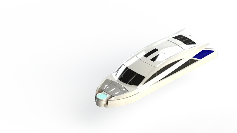
- A superstructure is an upward extension of an existing structure above a baseline.
- The superstructure is a ship/ yacht is the part that emerges from the deck.
- In this yacht superstructures like the front seat, middle seat, rear seat and cabin are modelled.
- The superstructure may be built in multiple layers.
- In this yacht single layer superstructures are used.
- Space for living accommodation, meeting room etc. are provided inside superstructures.
Features used to create Superstructure
- Sketch
- 3D Sketch
- Surface Extrude
- Surface Sweep
- Surface Knit
- Ruled Surface
- Curve
- Surface Loft
- Surface Fill
- Surface Trim
- Delete Face
- Fillet
- Surface Extend
- Extrude Boss
- Extrude Cut
- Surface Offset
- Dome
- Sweep
- Split Line
- Mirror
- Chamfer
Procedure for modelling Yacht Rear seat in brief.
- Insert the blueprint of the yacht in a new part.
- Create half of the superstructure by surface modelling and convert it into a solid body.
- Create a foundation tank on the front side of the superstructure.
- Provide handle for on the surface of the foundation tank.
- Create steps in the front portion of superstructure.
- Create glass window portion on the surface of the superstructure.
- Create a wiper part over the front window.
- Create a handle for the backside door of the superstructure.
- Create a surface on the foundation tank and provide appropriate transparency on it.
- Apply colour to all the necessary surfaces.
- Rendered images of the yacht superstructure are shown below.
10. Radar Mast
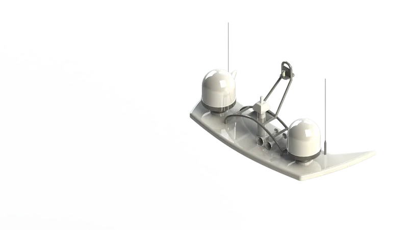
Radar mast is the mounting device of the radar in the ship. It is usually placed above superstructure. It has an appropriate position for keeping all the radar related equipment such as a transmitter, receiver, processor etc. Air horns are also fixed in radar mast.
Features used to create Radar Mast
- Sketch
- Extrude Boss
- Fillet
- Revolve
- Sweep
- Mirror
- Curve
- Chamfer
- Dome
- Shell
- Combine
Sweep:- It is used to create a 3-D profile or same cross-section along with any 2-D sketch.
Combine:- It is used to combine two or more than two 3-D components.
Procedure for modelling Yacht radar mast in brief.
- Insert the blueprint of the yacht in a new part.
- Create the bottom plate of the radar and provide fillet to all the sharp edges.
- Create the cylindrical tank on the bottom plate.
- Provide fillet and chamfer to all the required edges.
- Create an antenna starting from the bottom plate.
- Create radar holder and light holder.
- Create two horns on the top of the bottom plate of radar mast.
- Create the remaining part of the radar mast by mirroring the part modelled till the last step.
- Apply appropriate colours to all the required surfaces.
- Rendered images of the yacht radar mast are shown below.
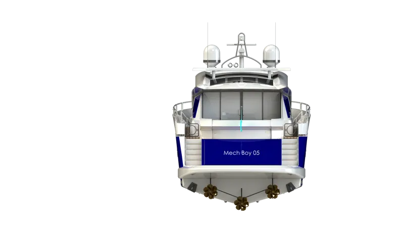
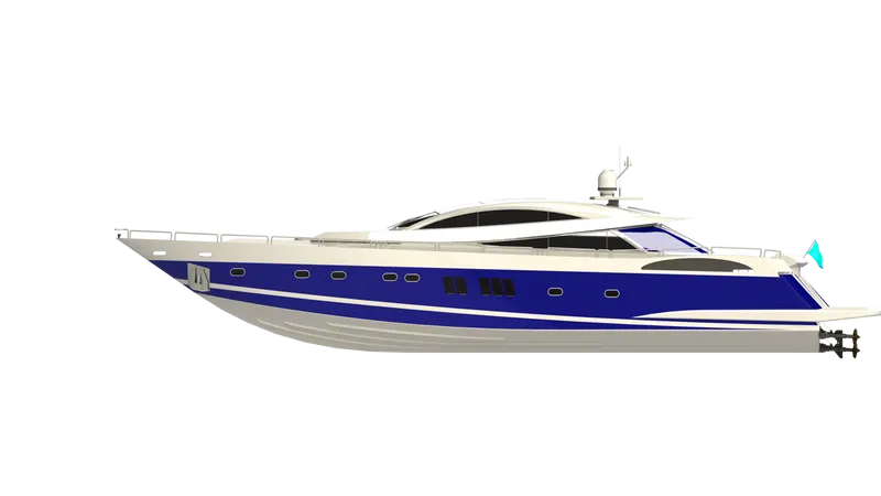
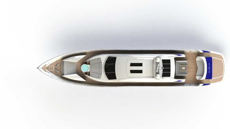
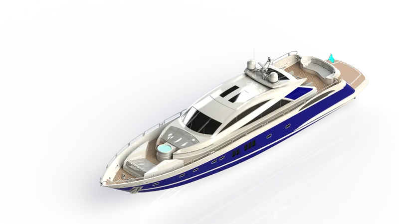
11. Assembly
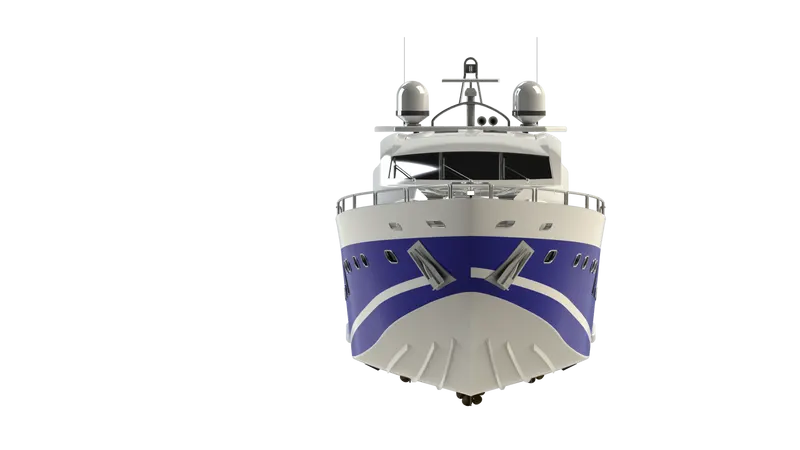
- The parts of the Yacht are inserted into the assembly environment.
- The possible mate conditions are given to the yacht and the yacht is assembled.
Rendering of the model of Yacht in SOLIDWORK visualize
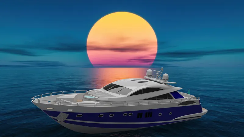
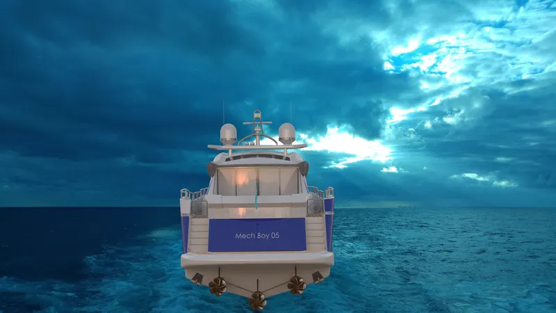
SOLIDWORKS VISUALIZE is the software used for rendering any model created in the SolidWorks. In this HDR environment, lighting conditions, camera position, etc. can be changed for getting rendering images. Following are some of the rendered images of Yacht in different environment and colours.
Conclusion:
- Knowledge of creating a 3-D model from blueprint.
- Knowledge of different modules like Sketch, Features, Surface, Evaluate, photo 360, Solidworks Visualize, etc. can be obtained while creating a 3-D model.
- knowledge of Render tools, Camera setup, add Decals, appearances, etc. can be obtained.