Photo Realistic Rendering
Design and Modelling of american chopper using SOLIDWORKS
INTRODUCTION
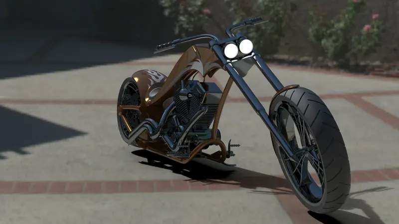
Chopper bikes are motorcycles featured on the television series of American Chopper for a specific corporate or celebrity customer. The Function of motorcycle usually takes a backseat to the presentation of the theme, and these motorcycles attract attemption soley on the premise of the theme itself.
OBJECTIVE
The objective of the project is used to create a model of different parts of American chopper bike like chassis, engine, wheel, fork, etc..., and assembly with the different parts of chopper and to create photorealistic model of the chopper and rendering the model by using software called solid works photo view 360.0
Part Modelling
part modelling is the process of creating a virtual prototype of something by modeling each individual part separately, which can then all be assembled together to create the model of the final product. Think all of the different parts of a car engine for example.
The main parts of the chopper are: The following parts of the chopper are used for a model and assembly in solidworks.
1. Transmission Belt
2. Kick Stand
3. Front fender
4. Rear fender
5. Oil tank
6. Chain
7. pedal
8. Front Wheel
9. Rear Wheel
10. Front fork
11. Chassis
12. Engine
13. Gas tank
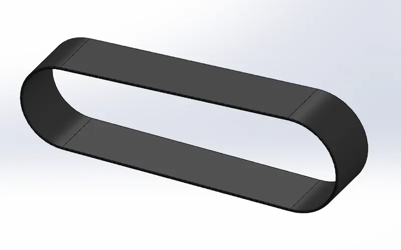
1. Transmission Belt
The main purpose of transmission belt is used to transmit power which is developed inside the engine to gear box with maximum efficiency.
Tools used:
Sketch tools:
1. 3 point Arc
2. Line
3. Sketch offset
Features:
1. Extrude
2. Fillet
3. Appearance
4. Sketch
5. Offset
Procedure for modelling:
1. First open solid works then select new part to create model
2. Then change the default names of the planes as
Front plane in to Front plane Transmission belt.
Top plane in to Top plane Transmission belt.
Right plane in to Right plane Transmission belt.
3. Then select front plane transmission belt to create 2D sketch and draw a sketch and give the dimessions, relations to sketch for fully defined.
4. Then offset the sketch with some distance by using offset command then exit the sketch.
5. Then extrude command is used convert 2D sketch into 3D model.
6. Then fillet is applied to belt as per requirements and model of transmission belt is created and change appearance of the belt and save the model.
2. kick Stand
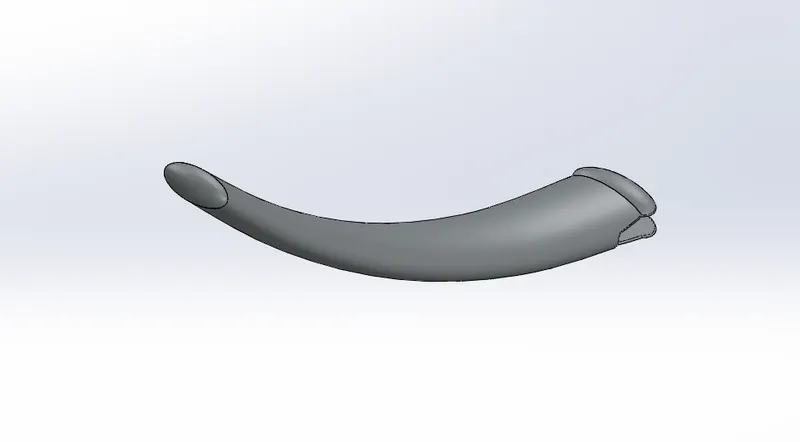
Kick stand or Side kick stand is a machine component used to support the motorcycle in rest position. The kickstand is mounted to the chassis through a mounting point. This component should have a high tensile/compressiove strength to withstand the load of bike while in rest position. The side stand is mounted generally on the left side of the chassis lower and has a free movement of 90 degrees so that stand can be swayed up when not required or while driving.
Tools used:
Sketch tools
1. Ellipse
2. Spline
3. Pierce
Features:
1. Sketch
2. Dome
3. Extrude Cut
4. Split
5. Loft
6. Extrude boss
7. Fillet
8. Appearances
Procedure for modelling:
1. First open solid works then select new part to create new model.
2. Then change the default names of the planes as
Front plane in to Front plane.
Top plane in to Top plane.
Right plane in to Mid plane.
3. Then select mid plane for sketching.
4. Then draw the 2D sketch by using the sketch commands, spline and trim commands and apply dimensions, relations for fully defined the sketch.
5. Then create new planes and draw ellipse in new planes as per required.
6. Then use loft command for create a loft to kick stand.
7. Extrude cut command is used to cut unwanted parts in the kick stand and change the appearance of kick stand and save the model.
3. Front Fender:
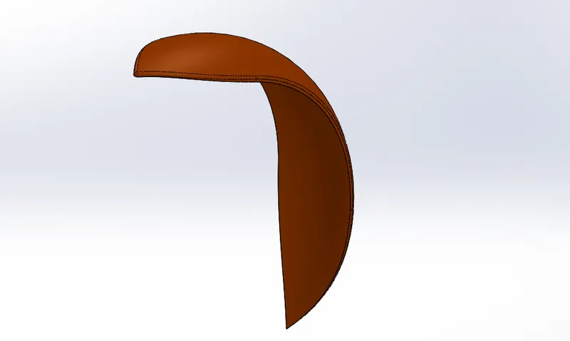
A Fender is the part of vehicle that protects and frames its wheels and keeps mud from splashing it. Most modern vehicles have fenders on their front and back wheels.
Tools used:
Sketch tools:
1. 3-Point Arc
2. Sketch offset
3. Line
4. Spline
Features:
1. Sketch
2. Trim entities
3. Dynamic mirror
4. Fillet
5. Offset entities
6. Revolve
7. Split
8. Appearance
Procedure for modelling:
1. First open solid works then select new part to create new model.
2. Then change the default names of the planes as
Front plane in to Vertical plane Front fender.
Top plane in to centre plane Front fender.
Right plane in to Mid-plane Front fender.
3. Then select vertical plane front fender for sketching
4. Then draw the 2D sketch by using sketch commands, splines and trim commands and apply dimensions, relations for fully defined the sketch.
5. Then change the appearance of front fender and save the model.
4. Rear Fender:
Its primary purpose is to prevent sand, mud, rocks, liquids, and other road spray from being thrown into the air by the rotating tire. Fender are typically rigid and can be damaged by contact with the road surface.
Tools used:
Sketch tools:
1. Line
2. Spline
3. Sketch offset
4. 3-point arc
Features:
1. Revolve
2. Shell
3. Fillet
4. Split
5. Dynamic mirror entity
6. Appearance
Procedure for modelling:
1. First open solid works then select new part to create new model
2. Then change the default names of the planes as
Front plane in to Vertical plane Rear fender.
Top plane in to centre plane Rear fender.
Right plane in to Mid-plane Rear fender.
3. Then select centre plane Rear fender for sketching.
4. Then draw the 2D sketch by using sketch commands, spline and trim commands and apply dimensions, relations for fully defined the sketch.
5. Then change the appearance of the rear fender and save the model.
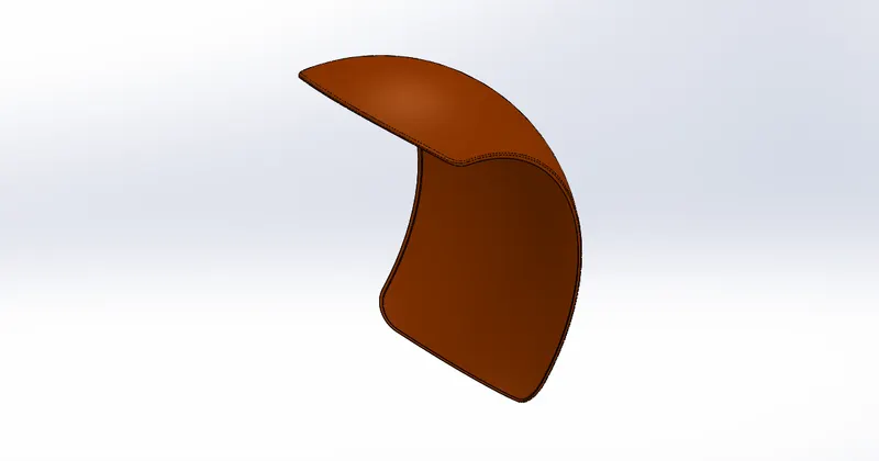
5. Oil Tank:
The oil tank is used as a reservoir to meet the oil requirements of the engine and to lubricate the parts. it is hollow in nature.
Tools used:
Sketch tools:
1. 3-Point arc
2. Line
Features:
1. Fillet
2. Shell
3. Extruded boss/base
4. Combine
5. Appearance
Procedure for modelling:
1. First open solid works then select new part to create new model
2. Then change front plane into midplane oil tank and select top plane for sketching
3. Then draw 2D sketches by using sketch commands, then add dimensions and relations as we required for fully defined the sketch, then combine model.
4. Then do shell and fillet commands and change the appearance and save the model.
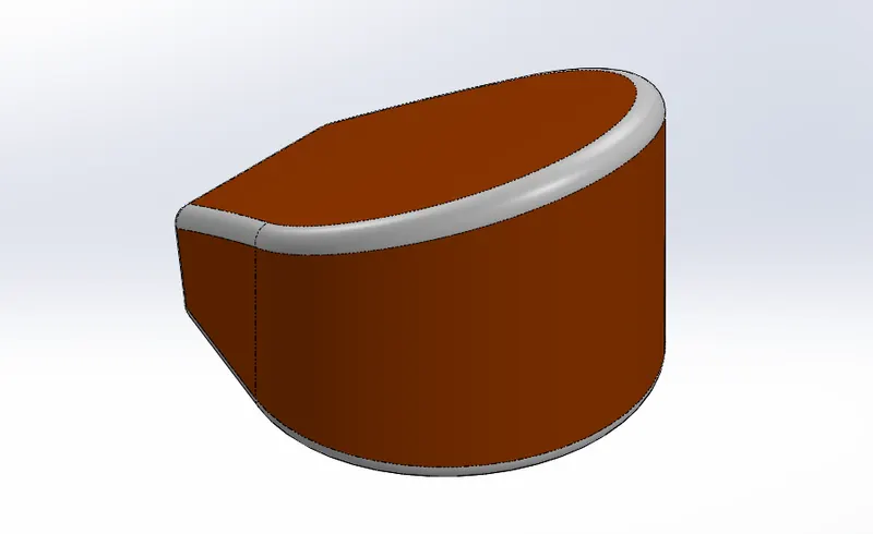
6. Chain:
A chain is a type of transmission system that is used to transmit a power from the Engine to the Rear Wheel. Chain is made of steel. The Sprocket is used to transmit the power to the chain. The sprocket is connected with the shaft with the help of key.
Tools used:
Sketch tools:
1. Centrepoint slots
2. 3-Point arc
3. Circle
Features:
1. Extrude boss
2. Make and save block
3. curve driven pattern - tangent to curve
4. Mirror
5. Appearance
Procedure for modelling:
1. First Open the solid works then select new part to create new model
2. Then change the default names of palnes as
Front plane in to Midplane chain
Top plane in to centre plane chain
Right plane in to Front plain chain
3. Then draw 2D sketches by using the sketch commands, and give dimensions and relations as we required for fully defined the sketch.
4. Then use curve driven pattern and fillet the chain.
5. Then change the appearance of chain and save the model.
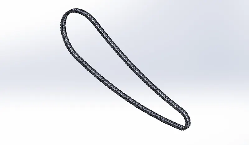
7. Pedal:
It is the external part attached to the chassis. Used to reset the foot of the rider on to it for the purpose of comfort.
Tools used:
Sketch tools:
1. 3-Point arc
2. Spline
3. sketch fillet
4. Circle
5. Line
Features:
1. Revolve
2. Dome
3. Linear pattern
4. Revolve
5. Fillet
6. Chamfer
7. Extruded boss
8. Appearance
Procedure for modelling:
1. First open solid works then select new part to create new model
2. Then select front plane for 2D sketch
3. Then draw all 2D sketches by using sketch commands, and add dimension and relation as per required for fully defined the sketch.
4. Then apply dome, fillet and chamfer commands to sketch.
5. Then add linear pattern curve for sketch and change the appearance of sketch.
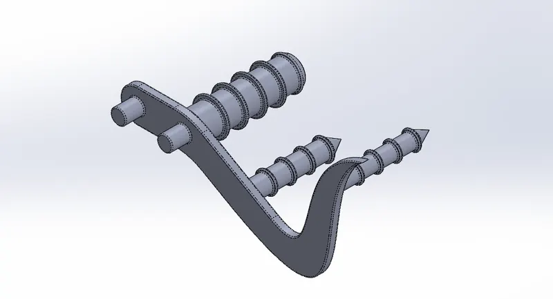
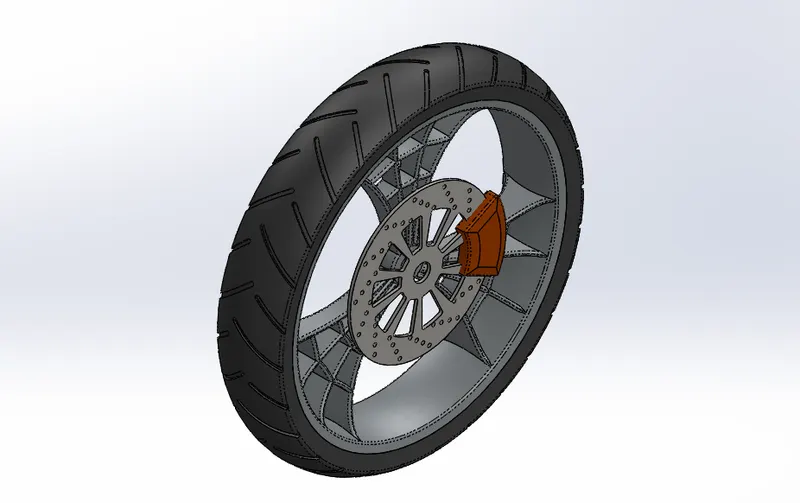
8. Front Wheel:
A Wheel is a circular block of a hard and durable material whose center has been boared a circular hole through which is placed an axle bearing about which the wheel rotates when a moment is applied by gravity or torque to the wheel about its axis.
Tools used:
Sketch tools:
1. Lines
2. Mid-plane line
3. Sketch fillet
4. Extend
5. 3-Point arc
6. Splines
7. circle
8. Trim
9. 3-Point centre rectangles
Features:
1. Extrude boss/base
2. Revolve boss/base
3. Revolve cut
4. Extrude cut
5. Combine
6. Circular Pattern
7. Chamfer
8. Fillet
9. Appearance
Procedure for modelling:
1. First open solid works then select new part to create model
2. Then select front plane for 2D sketch.
3. Then draw all 2D sketches by using sketch commands, and add dimensions and relations as per required for fully defined the sketch.
4. Then apply linear pattern, circular pattern, fillet, chamfer, combine commands to sketch.
5. Then change the appearance of the front wheel
9. Rear Wheel:
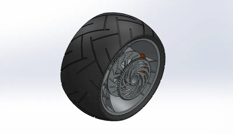
Rear Wheel is situated at rear portion of chassis. The rear wheel carries the large sprocket and disc. The power is transmitted to rear wheel from the gearbox through the chain.
Tools used:
Sketch tools:
1. 3- point arc
2. Splines
3. Circle
4. Trim
5. Lines
6. Mid-point line
7. Sketch fillet
8. Extend
9. 3-Point centre rectangles
Features:
1. Revolve boss/base
2. Extrude boss/base
3. Revolve cut
4. Extrude cut
5. Combine
6. Chamfer
7. Fillet
8. Circular Pattern
9. Appearance
Procedure for modelling:
1. First open solid works then select new part to create new model.
2. Then select front plane for 2D sketch.
3. Then draw all 2D sketches by using sketch commands, and add dimensions and relations as per required for fully defined sketch.
4. Then apply linear pattern, circular pattern, fillet, chamfer combine commands to sketch.
5. Then change the appearance of a rear wheel.
10. Front Fork:
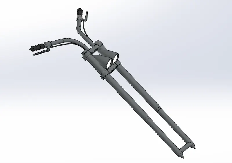
Front Fork connects a motorcycle's front wheel and axle to it's frame, typically via yoke, also known as a triple clamp, which consists of an upper yoke joined to a lower yoke via a steering stem, a shaft through the steering head, creating the streeing axis. Most forks incoporate the front suspension and front brake and allow the front wheel to rotate about the steering axis so that the bike may be steered.
Tools used:
Sketch tools:
1. 3-point arc
2. Splines
3. Trim
4. Lines
5. Circle
Features:
1. Linear pattern
2. Extrude cut
3. Revolve cut
4. Revolve boss/base
5. Extrude boss/base
6. Body move/copy
7. Curve-projected
8. Dome
9. Sweep
10. Mirror
11. Combine
12. Reference geometry-planes
13. Chamfer
14. Fillet
15. Appearance
Procedure for modelling:
1. First open solid works then select new part to create new model
2. Then select front plane for 2D sketch.
3. Then draw all 2D sketches by using sketch commands, and add dimensions and relations as per required for fully defined sketch.
4. Then mirror the object and change the appearance of object.
11. Chassis:
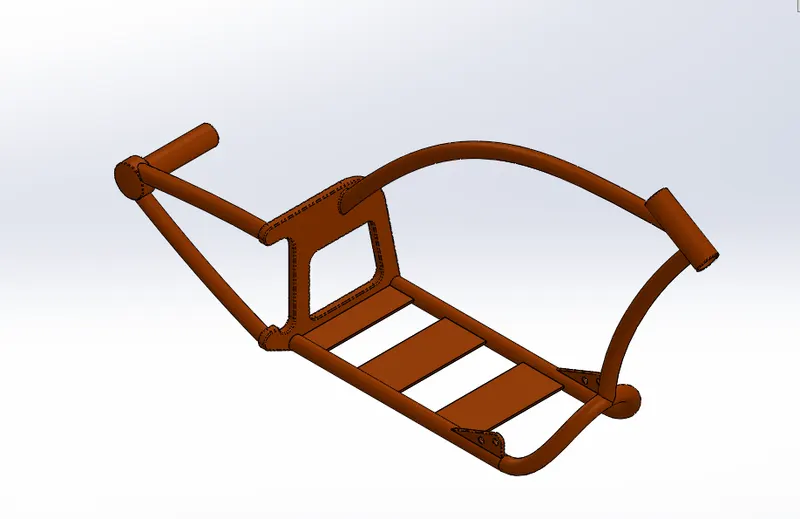
A chassis is the load bearing framework of a chopper which structurally supports its function and construction. All the parts of a vehicle wheels, transmission, fuel tank etc. are mounted on it.
Tools used:
Sketch tools:
1. Sketch Picture
2. Splines
3. Trim
4. Lines
5. Circle
Features:
1. Extrude boss/base
2. Extrude cut
3. curve-projected
4. Revolve
5. Dome
6. Sweep
7. Mirror
8. Split
9. Combine
10. Reference geometry-planes
11. Chamfer
12. Fillet
13. Appearance
Procedure for modelling:
1. First open solidworks then select new part to create new model
2. Then change the default names of planes as
Front plane in to Midplane chassis
Top plane in to bottom plane chassis
3. Then select midplane chassis for sketch then bring the sketch picture in the midplane chassis and the change the x and y direction positions and transparency as per required
4. Then exist the sketch and rename the sketch as blueprint chopper.
5. Then draw the 2D sketches by using planes, and sketch commands and give dimenssions and relations as per required to fully defined the sketch.
6. Then change the appearance of chassis and save the model.
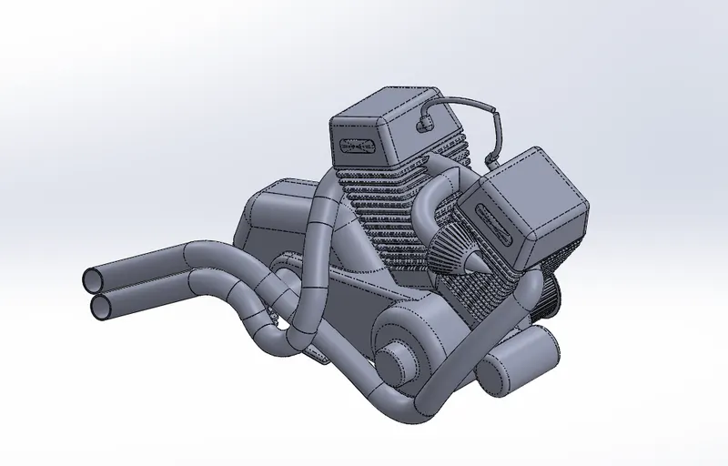
12. Engine:
An Engine is a machine desige=ned to convert the chemical energy of a fuel into thermal or heat energy and then the thermal energy into mechanical energy or mechanical work engine consistsn of piston, a cylinder block and a head, which contains the valve train. The pistions move up and down in the cylinder block, driven by explosions of a fuel-air mixture that has been ignited by a spark. valves open and close to allow the fuel-air mixture to enter the combusion chamber. As the piston move up and down, then turn a crankshaft, which transforms the energy from the pistons into rotary motion. The rotational force of the crankshaft is transmitted force of the crankshft is transmitted, via the transmission, to the rear wheel of the motorcycle.
Motor cycle engines are generally classified by one of three characteristics the number of cylinders they possess, the capacity of their combusion chamber or the number of strokes in the power cycle.
Tools used:
Sketch tools:
1. Sketch Picture
2. Splines
3. Lines
4. Circle
5. Circular sketch pattern
6. Construction line
7. Centre point rectangle
8. 3-Point centre rectangle
9. Trim
Features:
1. Extrude cut
2. Extrude boss/base
3. Dome
4. Composite curves
5. Curved-projected
6. Revolve
7. Split
8. Sweep
9. Reference geometry-planes
10. Circular pattern
11. Linear pattern
12. Mirror
13. Combine
14. Fillet
15. Chamber
16. Appearance
Procedure for modelling:
1.First open solid works then select new part to create new model.
2. Then select front planes for sketch and then bring the sketch picture in the midplane chassis and the change the x and y directions positions and transparency as per required.
3. Then exit the sketch and rename sketch in to blueprint chopper.
4. Then draw the 2D sketches by using planes, and sketch commands and give dimensions and relations as per required to fully defined the sketch.
5. Then change then appearance of engine and save the model.
13. Gas Tank
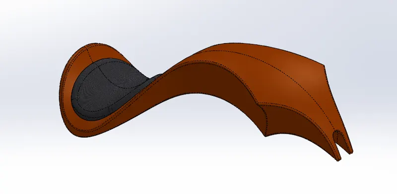
A Gas tank is a safer container for flammable fluids. Through any storage tank for fuel may be so called, the term is typically applied to part of an engine system in which the fuel is stored and propelled (fuel pump) or released (pressurized gas) into an engine. Fuel tanks range in size and complexity from the plastic tank of a butane lighter to the multi-chambered cryogenic space shuttle external tank.
Tools used:
Sketch tools:
1. Sketch Pitcure
2. Lines
3. Splines
4. Construction line
5. trim
Features:
1. Surface sweep
2. Surface loft
3. surface trim
4. Boundary surface
5. Surface extrude
6. Surface Knit
7. Curves
8. Projected curves
9. Split line
10. Sweep cut
11. Reference geometry-planes
12. Mirror
13. Fillet
14. Shell
15. Appearance
Procedure for modelling:
1. First open solidworks then select new part to create new model.
2. Then change the default names of planes as
Front plane in to Midplane gas tank
Top plane in to bottom plane ga tank
Right plane in to front plane gas tank
3. Then select midplane gas tank for sketch then bring the sketch picture in the midplane gas tank and the change the x and y direction positions and transparency as per required.
4. Then exist the sketch and rename sketch in to under lay gas tank.
5. Then draw the 2D sketches by using planes, and sketch commands and give dimensions and relations as per required to fully defined sketch.
6. Then change the appearance of gas tank and save the model.
Assembly of Chopper: The main purpose of assembly of chopper is that assembly the all individual parts with suitable mates.
The following procedure is used to create a Assembly of American chopper:
1. Cick on file then open all the components and then open assembly file.
2. Then open insert components and then select chassis and then ok.
3. Then insert engine manually in rough position, then select front plane of engine and front plane of assmbly and make coincident each other
4. Then select bottom face of motor and one of plate of frame and make coincident each other and then give distance between front face of plate and frame. Then replace front plane of assembly to midplane chassis then mate and save.
5. Then expand part and rebuild dimensions as per orientation and do collapse items.
6. Then isert pedal manually inside a assembly to position and then select outside pedal and inside of frame plate and make concetric and coincident. Again, open the engine part and then modify as per orientation and then open assembly file and save.
7. Then mirror the pedal by using the mirror component as per orientation and save.
8. Then insert the kick stand to nearest point of orientation and then mate the plate and kick stand. then make parallel between midplane of kickstand plate of frame and give the angles as per required and save.
9. Then insert transmission belt and drag in to the closest position and select belt and pulleys and make concetric each other and then select two outsides face of pulley and then go to advance mate then select two faces of belt and pulley and then mate and then modify the belt dimensions as per orientation and then collapse items and save.
10. Then insert oil tank and select bottom face of oil tank and top face of motor and make coincident and then select midplane of oil tank and midplane of chassis and make coincident and then save.
11. Then insert rear wheel in to nearest place and then change y direction as per orientation and then concetric between inside of wheel and axle.
12. Then select right plane of rear wheel and midplane of chassis and make coincident and then select right plane of chassis and front plane of rear wheel and make parallel and then collapse items and save.
13. Then insert rear fender in correct orientation by changing y and z directions and then select the one side of fender and tire face and make concetric and then select midplane of Rear fender and midplane of chassis and make coincident and again select plane of rear fender and right plane of chassis and make parallel and save.
14. Then insert the chain to nearest place and then select midplane of chain and midplane of chassis and make parallel to each other, Then mate the chain and sprocket with each other and then collapse items and save.
15. Then insert gas tank in the closest place and then select front plane of fuel tank and plane 2 of chassis and make coincident each other and then select bottom plane of fuel tank and bottom plane of chassis and then make coincident and modify the one of coincident mate as per orientation and save.
16. Then insert front fork to front face of model and then select stem of fork and front part chassis and make concentric each other.
17. Then mate the upper and lower arms and top and bottom of section and control the angle by using mate command between front plane of fork and midplane of chassis and select midplane of chassis and front plane of fork make parallel and collapse items and save.
18. Then insert front wheel by rotating y direction and make concentric with between wheel and axle.
19. Then create a plane by using roll back feature tree and midplane of fork and right plane of wheel and vertical plane of front fork and make coincident each other and save.
20. Then insert front fender by using changing direction of y direction as per orientation.
21. Then select vertical plane front fender and vertical plane fork and make coincident and then select centre plane of front fender and top plane of wheel and make coincident and mid plane of fender and right plane of wheel make coincident and collapse items and save.
22. Then edit chassis and chain as per orientation and save the file.
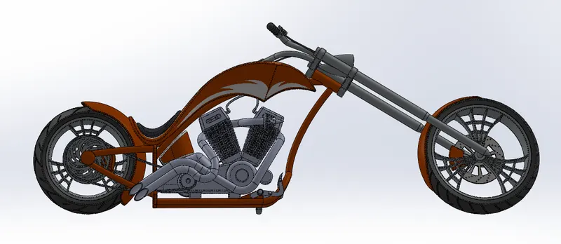
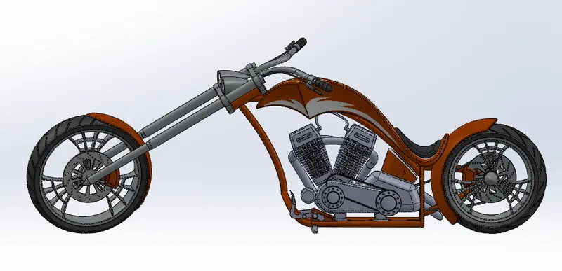
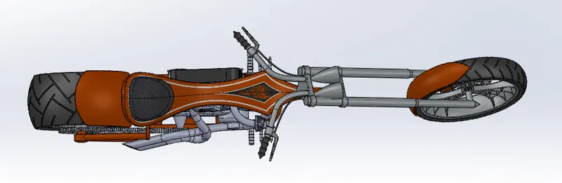
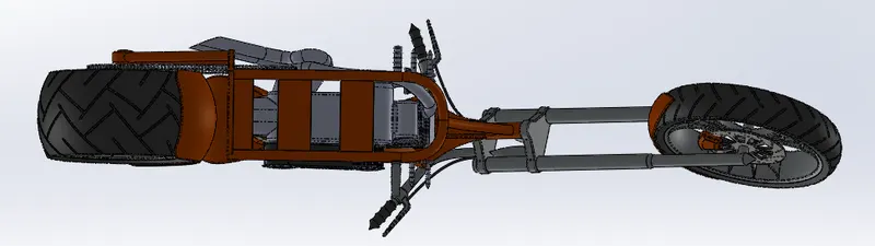
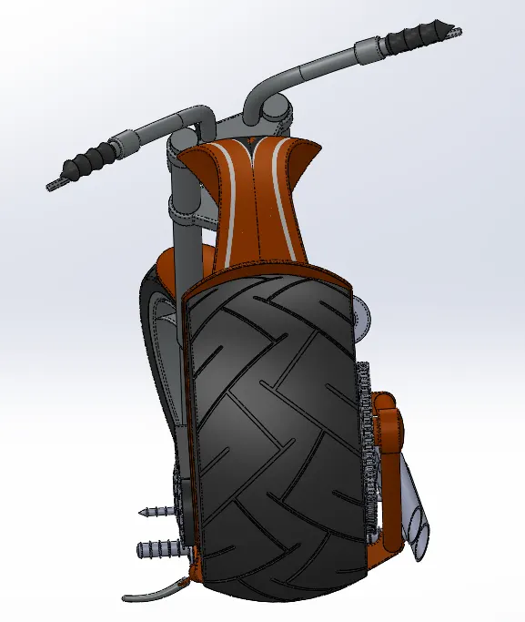
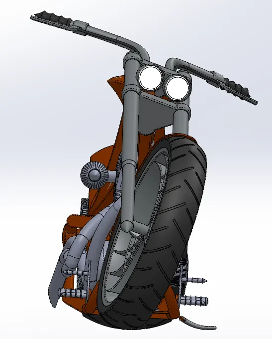
Images of Assembly: Following are the images of the chopper in different views,
Front View:
Back View:
Top View:
Bottom View:
Left side View:
Right side View:
Isometric View:
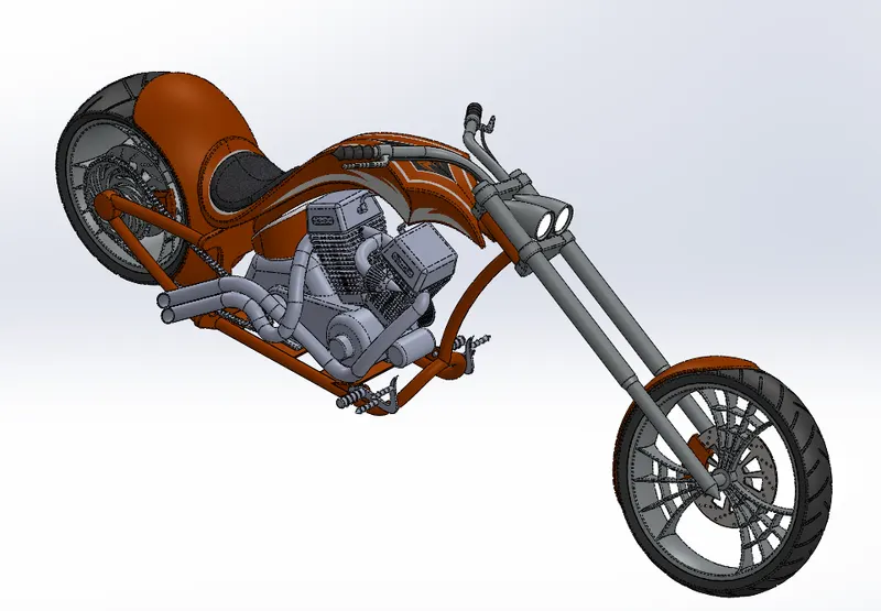
PHOTOREALISTIC RENDERED IMAGES OF AMERICAN CHOPPER
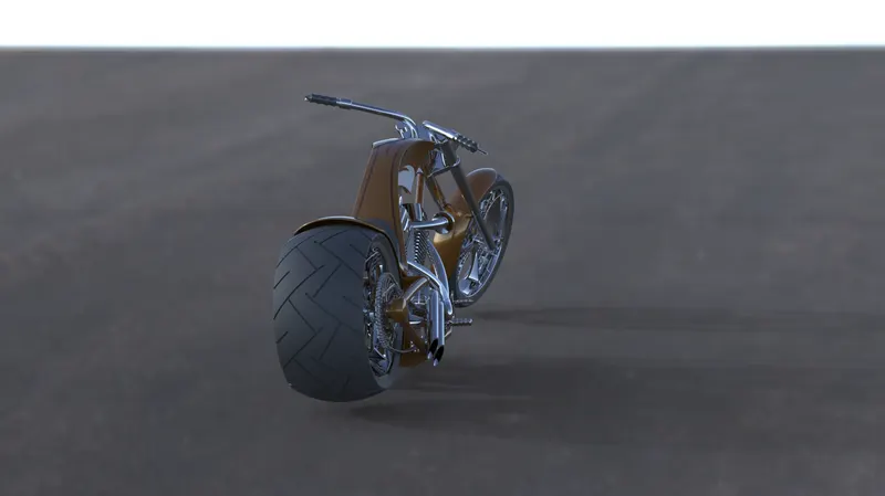
Rendering is the process of creating realistic images of the Photorealistic model with the environment. Rendering has been done in two ways in solidworks. The following are the two ways:-
1. Photoview 360
2. Solidworks Visualize
In the photorealistic model, some of the mate conditions and positions are changed to render realistic models. Then the photorealistic model is rendered into realistic images with different views.
Infinite Tarmac Light 2:
Sunny Driveway:
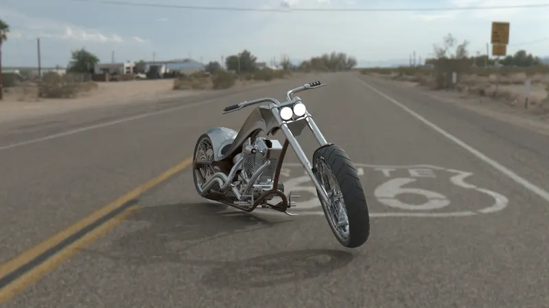
Route 66:
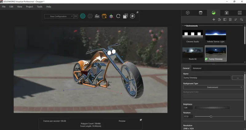
Solidwork visualize:
- Soliidworks visualize provides a suite of standalone software tool that combine industry-leading rendering capabilities with visual design-oriented feature and workflows, allowing easy and fast creation of visual content that communicates a design's vision, passion, and emotion.
- it is a separate render engine that is provided under solidworks professional.
- Visualize Professional adds an array of features including animations, custom lighting, VR, 360 interactive, and much more.
- Solidworks Visualize Professional provides the highest level of detail and optimized render times.
- It helps in creating Rendered images of the solidworks model in Photorealistic environments for marketing quality images with various options to tweak on the final image as per the user.
- It uses either of the CPU or GPU or both hybrid to render quality images.
CONCLUSION:
- All the exterior parts of the chopper are modeled successfully under SolidWorks modeling environment.
- All the parts are inserted into the assembly environment and the chopper is successfully assembled.
- The photorealistic image is successfully rendered with the use of the Photoview 360 & SolidWorks Visualize.