Radar Mast & Final Assembly of Yacht
MODELING OF YACHT ON
SOLIDWORKS
By
S.Prasanna Raj
INTRODUCTION
In this project we learn about the design of Yacht assembly with help of SOLIDWORKS. In this we first learn to use the commands and then we draw parts. By using blueprint sketch, we get idea of sketching the parts and its dimensions. After designing all the parts we do assembly of Yacht.
The components which we learnt in Yacht are:-
- Front Seat
- Garage Door
- Hull Part
- Middle Seat
- Propeller
- Radar
- Radar Mast
- Rear Seat
- Super Structure
OBJECTIVE:-
- To learn the basic commands of
- With the help of blueprint sketch we design all the parts of
- Assembling all the parts in
4
- Rendering of Yacht has done with help of solidworks visualization
Design approach:- There are two types of approach in design procedure.
- Bottom up approach and
- Top down approach. Here in this project we have used Bottom-up approach, we get clear idea by defining these terms.
- Bottom up approach: The design approach in which the most primary operations are specified first then combined it later to make larger progressive
- Top down approach: Top down assembly modelling is an assembly-centric modelling method where the assembly design is started at the highest level possible, and individual parts and subassemblies are defined within the context of the overall
|
|||
Let’s see what are the features and properties used in the entire model to design different parts:-
- Extrude boss
- Fillet
- Revolve boss feature
- Extrude cut
- Shell
- Linear pattern
- Mirror
- Reference geometry
- Projected curve
- Knit
- Mate
- Extrude Boss :-
Extrude Boss/Base is one of the important and very useful tool in Soildworks CAD software to create solid 3D models. It extrudes a sketch or selected sketch contours in one or two directions to create solid feature. That means, if you have closed contour sketch drawing, then you can add materials to that contour and convert it into 3D model.
- Fillet:-
The Fillet feature is one of the oldest features in SOLIDWORKS software. It was included in the software when the product was first released back in 1995. Most SOLIDWORKS users have created models utilizing the Fillet feature, but many users are unfamiliar with some of the great options available within the Fillet feature.
8
- Revolve boss feature:-
Revolved Boss or Base is a SolidWorks feature tool which is used to create solid 3D model around an axis. You can revolve the sketch around an axis to add materials to it. You can access revolved boss/base from both command manager and menubar.
- Extrude cut:-
By Tonasam Solid works Tutorials 0 Comments Extrude cut is another cool feature which helps to remove materials from the 3D model. It is just opposite to extrude boss/base feature, because it cuts a sketch profile while extruding. You can cut in both directions and mainly used for creating holes, channels, slots etc.
9
- Shell:-
Solid Works shell tool is mainly used for shelling process, in which the material removed from the inner body of model by keeping small thickness and results a hollow model. Using this tool, you can make either completely closed hollowed model or one face opened type.
Linear pattern:-
Linear pattern is a continuous design, that can be expanded on two sides. The pattern follows the direction of the shape, containing the design – like a pattern on a ribbon follows the ribbon.
Mirror:- This feature creates copy of solid part. When this feature is applied it need plane or axis to mirror. Select the body which is to be mirror, select an axis or plane then apply feature and the mirrored part will get. Multibody parts: Apply feature to one or more multibody parts by selecting geometry pattern and using feature scope to choose which bodies should include the feature.
11
Reference geometry:-
Reference geometry is geometry that we create to be used as reference for the creation of new sketches and features. The types of reference geometry that exist are planes, axes, coordinate systems, and points. We will save axes, coordinate systems, and points for you to learn on a case by case basis when you get more familiar with Solid Works.
Use of reference geometry example:
- Axis: If we want to pattern something and axis is not available by using reference geometry axis it gets easier to make
- Plane: If we need to sketch and there is need of plane by using reference geometry plane we can draw it and complete the sketch.
- Projected curve:-
Projected Curves You can project a sketched curve onto a model face to create a 3D curve. You can also create a 3D curve that represents the intersection of two extruded surfaces generated by creating sketches on two intersecting planes. You can create multiple closed or open-contour projected curves from a single sketch.
Knit:- Use of knit surface tool to combine two or more faces and surfaces into one. It create a solid body when the knit surfaces form a closed volume or leave as a surface body.
Mate:- Mate creates geometric relationship between assembly and component. When we add mates, it defines the allowable direction of linear or rotational motion of component within its degree of freedom, visualizing the assembly’s behavior.
This feature includes:-
- Coincident mate: Coincident mate make two planar faces to become This mate can move along one another but cannot be separated.
13
- Concentric mate: This makes two circular faces to become concentric and can move along the common
- Tangent: This feature can be use between a face and plane to make tangent
- Angular mate: This make angular relation between flat surface and the surface having some
Now we have completed discussion of how the features work under solid works. Let us see the application of the features in the chopper that we have built. We are going to discuss part by part as shown in the flowchart.
14
Front Seat:- Front Seat is located at the Deck Surface of the Yacht. Seating area of the yacht.
Features used to create the transmission belt:
- Sketch
- Surface Sweep
- Surface Sweep
- Surface Fill
- Extrude Cut
- Revolve
- Fillet
- Chamfer
- Mirror
- Dome
- Appearance
Garage Door:- While designing Garage Door first we have created sketch based on an additional plane, we applied fillets to the edges and at the joints of the part.
Features used to create the kickstand:
- Sketch
- Shell
- Pierce
- Mirror
- Cut extrude
- Boss extrude
Hull Part:- Here we revolved the sketch using an axis and created half curved solid body. Some sharp edges designed on the both sides by using the split tool the material is removed. The edges are filleted.
Features used to create the Front fender:
- Sketch
- Projected Curve
- Offset
- Extend
- Trim
- Surface Knit
- Surface Trim
- Surface Fill
- Surface Extrude
- Surface Loft
- Extrude
- Shell
- Cut Extrude
- Fillet
- Chamfer
- Sweep
- Extrude Thin
- Dome
- Helix/Spiral
- Linear Pattern
- Surface Cut
- Combine
- 3D Sketch
- Split Line
- Mirror
- Revolve
- Spline
Middle Seat:- Same procedure is used to make Middle Seat as it was used in Front Seat. It is also created by using the Hull Part as a reference.
Features used to create the Rear fender:
17
- Sketch
- Boss Extrude
- Chamfer
- Trim
- Mirror
- Extrude Cut
- Fillet
Propeller:- It is used to move the yacht from the force. Fillet is applied on the outer edges to make it round.
Features used to create the Oil tank:
- Revolve
- Loft
- Extrude Cut
- Boss extrude
- Circular Pattern
- Fillet
- Shell
Radar:- To create Radar first we need to draw the sketch using arcs and lines, the line must be tangent to the arc. A fine finished Radar has been created.
Features used to create the Chain:
- Sketch
- Boss Extrude
- Fillet
- Cut Extrude
- Sketch Pattern
- Mirror
- Split line
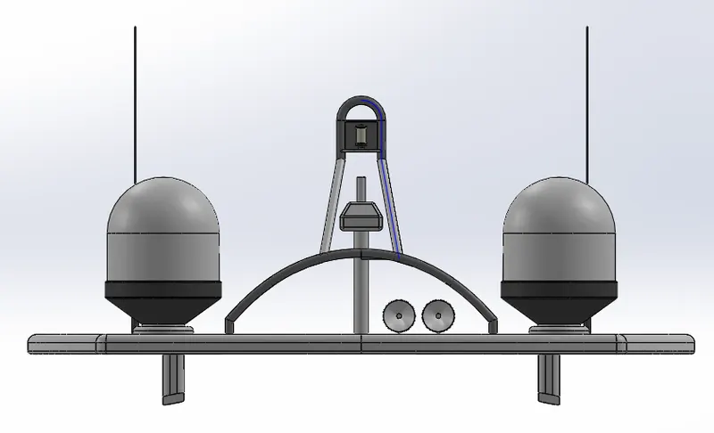
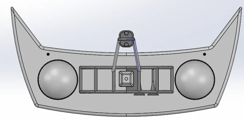
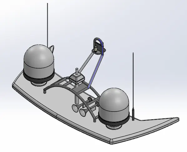
Radar Mast:- A mast system is composed mainly of supporting frames, a circular base plate, radar, and an antenna. The various features are used to create the Radar mast are splines, fillets, dome, chamfer and linear pattern.
Features used to create the Pedal:
- Sketch
- Boss Extrude
- Sweep
- Fillet
- Revolve
- Dome
- Mirror
- Chamfer
- Projected Curve
21
Rear Seat:- The rear seat is located at backside of the Yacht
Features used to create the Front wheel:
- Sketch
- Lines
- Surface Sweep
- Surface Offset
- Surface Trim
- Ruled Surface
- Surface Knit
- Surface Extend
- Surface Extrude
- Surface Loft
- Cut Extrude
- Boss Extrude
- Chamfer
- Revolve
- Mirror
- Spline
22
Super Structure:- The Super Structure is the Main Portion of the Yacht. It is the main structure of the Yacht to control it.
Features used to create the Rear wheel:
- Sketch
- Surface Extrude
- Surface Sweep
- Ruled Surface
- Surface Trim
- Surface Fill
- Surface Loft
- Surface Knit
- 3D Sketch
- Projected Curve
- Surface Extend
- Fillet
- Boss Extrude
- Cut Extrude
- Thicken
- Dome
- Split line
- Extrude Thin
- Mirror
- Chamfer
24
Assembly of the Yacht:- All the parts were modeled and were imported to assemble them. In assembly mate feature is most commonly used to locate and relate the parts with one another. Hull Part is main component which is inserted first and then fixed. The other components were inserted one by one and by using planes for reference and giving the mate feature once the part gets fixed it floats with the main frame. Some parts were modified during assembly to make it perfect according to requirement.
Radar Mast:
Front View:
Top View:
Isometeric View:
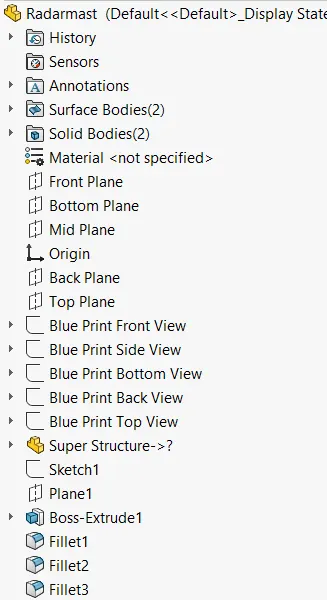
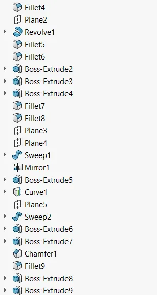
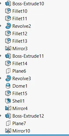
Tree Structure