Radar Mast & Final Assembly of Yacht
Design,Assembly & Photo-Realistic Rendering of an American Predator Yacht.
OBJECTIVE:-
Draft & desoign the individual components of a yacht & assemble them together to form a good asthetical appearance of Yacht.
INTRODUCTION:-
In this project the American Predator Yacht was taken as a conceptual model,to understand the 3D modeling methodology of Solid Modeling & Surface Modeling each & every part od the yach was designed & modelled using solidworks.Then the modelled parts were assembled by adding proper mates & constraints to create the Photo-Realisitic rendered image of the Yacht.
The solidworks is a mechanical design automation application that lets designers quickly sketch of the ideas,experiments with features & dimensions,& produce models & details drawings.
Photoview 360 is a solidworks add in that produce photo-realisitic rendering of solidworks models.The render images incorporates the appearance,Lighting ,scene & decals including with the model.
Solidworks Visualize is a photorealsitic rendering tool that utilize our CAD data to create magazine quality images or commercial quality animation.
DESIGN METHODOLOGY:-
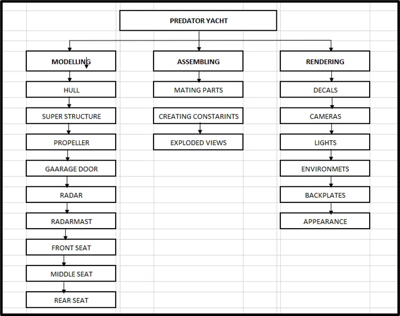
Present design of Yacht consist of following parts & Patterns:-
1) Hull
2) Superstructure
3) Radar
4) Radarmast
5) Garage door
6) Propeller
7) Front,Middle & Rear seat.
HULL:-
A hull is watertight body of a ship or boat.the hull may open at the top & it may be fully or partially covered with a deck.A top the deck may be deckhouse & other superstructures.such as derrick,or mast.The line where the hull meets the water surface is called the waterline.
The design of hull involes preparation of outer shell surface & the deck surface.Te water shell is drafted with the required curves initially & are extruded & lofted,to obtain the required the curves are drwan an different plane & they are projected so that the required curvature is obtained in betwen the planes.
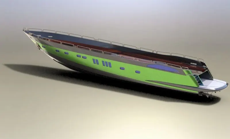
Commands used during hull designed:-
- Curve Projection:- It is one of the option in solid works tool which is give us the output curve for the two curves/lines drwan an different planes,this is the intersection path where the two extruded surface meet.
- 3D Sketch:- Very handy tool to drawn any lineor curve in spave as it is confimed to the axis helps to join the projected curves & work an different axis to create geometrical planes.
- Surface Extrude:- It is used to form surface bodies where the thickness is the thick.
- Surface Loft:- Loft is the option is used to prepare very difficult surface formed with the help of 4 different curves drwan a different planes.It involves two profile curves & one or more guide curves.
- Surface Knit:- It helps to eliminate the minor gaps exist between the two surface & join then together as like a single surface,The option works only for surface not for solid bodies.
- Sweep:- It helps to produce solid tube along the guided curves/line patch.
- Helix Spiral:- It is used to create any springs it screw threads as this option constrain pitch or height & revolutions with describes the how many rings with gap between them.
- Convert Entities:- It is available in 2D sketching tab with convert the edges of the 3D object to the line projected on to the surface.
SUPERSTRUCTURE:-
It is placed on the top od the hull.It is also a symetric model therefore it is enough to model one half so that the other half could be mirrored.It is modelled in way same as hull,the model is started in surface modellingwith a deck sirface imported from hull as reference.The desired surface are modeled & the surface model is converted into solid & proceeded with solid modeling.
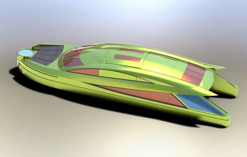
Commands used during Superstructure designed:-
- Ruled Surface:- It is used to obtain the extrude surface perpandicular do the plane of refernce & the added advantages of ruled surafce is that the surface can tiltled with & angle as prompted in the tool along with the length.
- Surface Trim:- This prompt select the refernce surface & next surface to be trimmed & it also options to keep the surface or remove the surface that was selected to trim.
RADAR:-
Radar is a device to used to detecting the objects.It is very improtant device in any yacht.It ismated with the part called radarmast & placed on the topmost part of the yacht.It is modelled in solid modelling.It is a systematic model so the other half is mirriored.The name is engraved using text & the extrude commands.
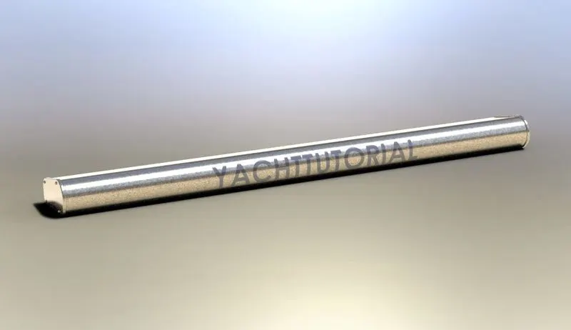
Commands used during Radar designed:-
- Extrude Boss/Base:- The sketch of the body of the radar cretaed using the extrude Boss/Base.
- Mirror:- Half of the body of the radar mirrored with help of mirror tool to complete the body of the Radar.
- Split Line:- The text over the Radar was created using the text option in sketch & then the split line was used to generate over the face of the Radar.
RADARMAST:-
It is device thatcomes with Radar,it is used to control the position & direction of the Radar.It also processes the signals which are sent & received.It is modelled based on the deck surface imported from the superstructure.
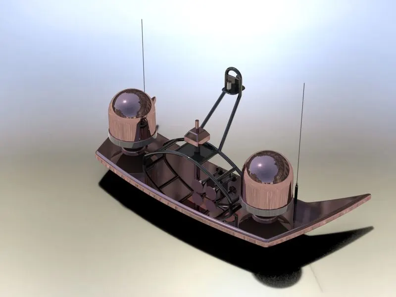
Commands used during Radar designed:-
- Revolve:- This tools requires a closed sketch with the central axis which helps to form the cylindrical objects to central axis.
- Shell:- This tool helps to create the shell to the solid body which prompts to enter the thickness & solid objects into shell type object with the wall thickness as provided.
GARAGE DOOR:-
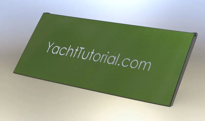
This part is modelled in a solid model which was saved when slpit command was used during modelling hull.The part is retrived & is used the constructions of the garage door.It is symmetric model,therfore the other half is mirrored.The name is engraved using text & cut extrude (Offset from surface) commands.
PROPELLER:-
Propeller looks like a fan,it is placed such that it submerged inside water .Propeller is the main component for the navigation of the Yacht,it receives power from the engine,it helps the yacht move forward or backword by pushing the water in opposite direction,for the instance if the ship is moving forward the propeller pushes the water backword & vice versa.
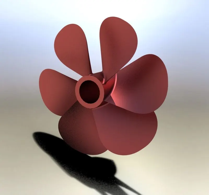
Commands used during Radar designed:-
- Revolved boss/base:- The center portion of the propeller was sketched & revolved usng Revolved Boss/Base.
- Circullare Pattern:- I any part of the body which requires the in multiple quantity in same pattern to used circullar pattern.
FRONT,MIDDLE & REAR SEAT:-
These front ,middle & rear seat are the accessories of the yacht for resring & sitting.
FRONT SEAT:-
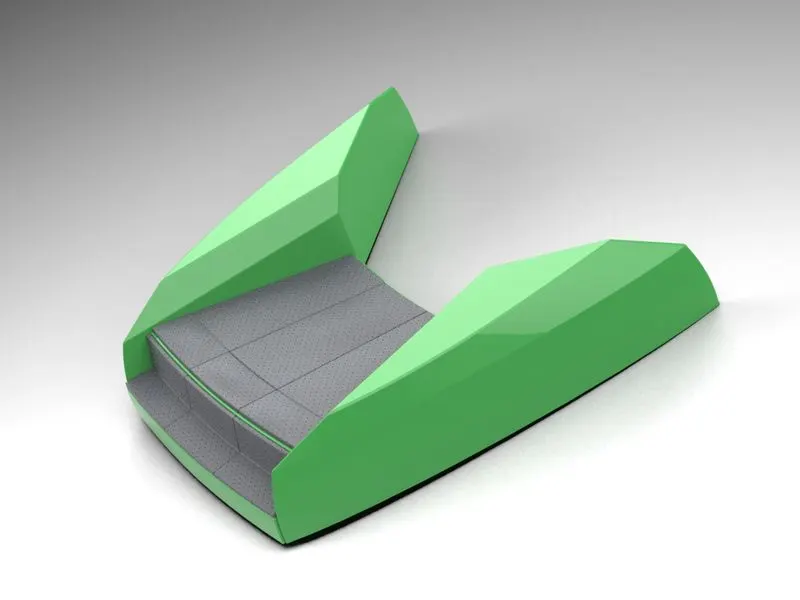
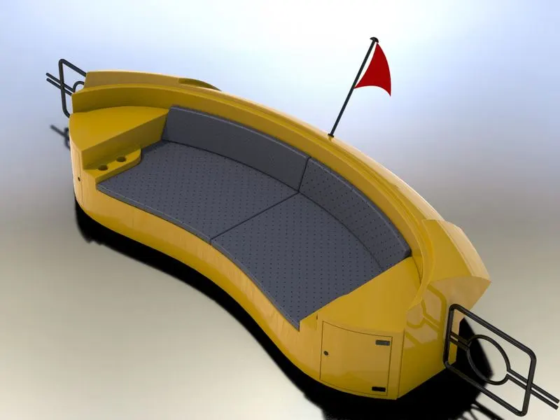
Front seat feature two connected seats that are built back to back from one and other.They have built in stoirage unit underneath them.lounge seat can also fully recline right back to make easierfor you to kick your feet up & get more comfortable.
MIDDLE SEAT:-
The middle seat in our model was placed just behind the superstructure.It is provided with a luxury table to dine out.It can also be used to have casual meetings with co-passengers.
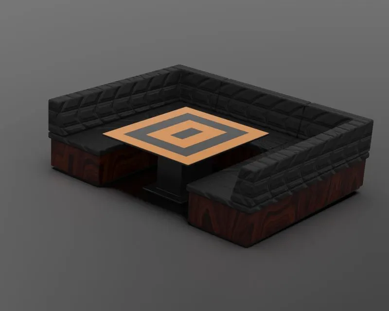
REAR SEAT:-
The rear seat was placed at the end of the deck surface.The rear seat consist of locker racks & steel doors for our stairs.The flag was laso plaved behind the rear seat.
ASSEMBLY:-
All the components are imported in to the assembly workbench are according t the the tree chart & applied mates to fix their position with respect to the fixed body or object.
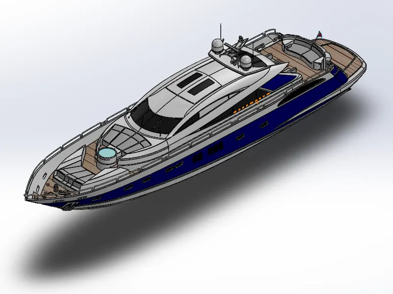
Commands used during Assembly of Yacht:-
- Smart Mate:- A smart mate is an assembly mating relatoion that is created autiomatically.
- Mate:- A mate is geomteric relationship,such as cincidents,perpandicular,tangent,& so on,between parts in an assembly.
- Mate Group:- A mate group is a collection of mates that are solved together.The order in which the mates appear within the mate group does not matter.
- Insert component:- We can insert multiple instances of the group of components without closing the property manager.
RENDERING:-
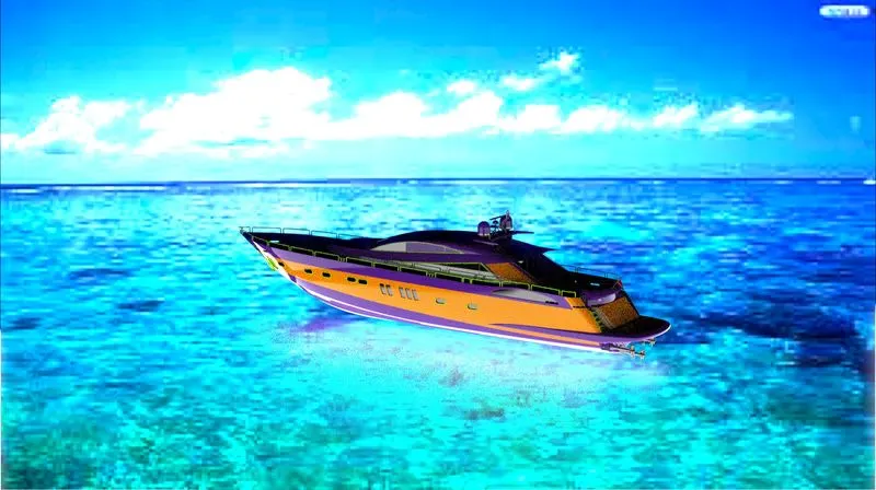
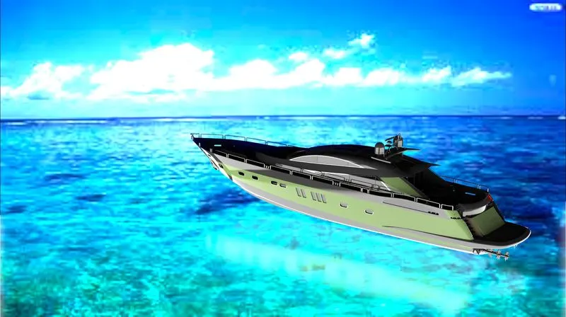
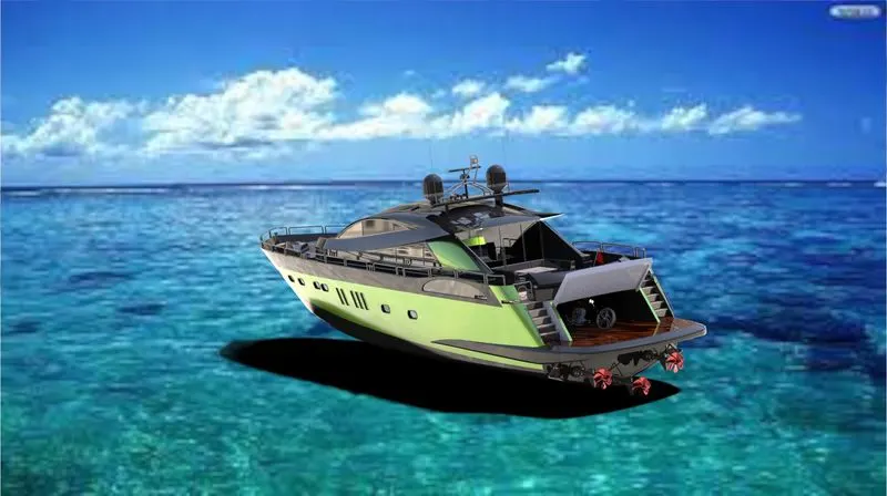
Rendering is the process of generating a photorealsitic image from 2D or 3D model by means of a computer prgram.The resulting image is reffered to as the render.
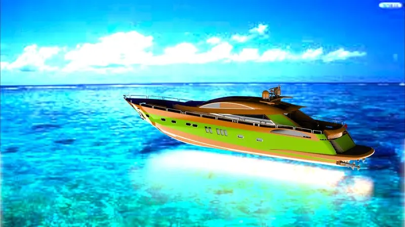
In solidworks rendering is done in solidworks visualizer.In this we need to import required solidworks part components & by backplate we get the rendered output images as shown below

PHOTOVIEW 360:-
Is a visualization & rendering solution included with solidworks.Providing with highly interactive environment for viewing designs as well as for creating renderings .It can be used to showcase pur designs.
SOLIDWORKS VISUALIZE:-
Its provide suit of stand alsone software tools that combine industry-leading rendering capabilities with visual designs-oriented features & workflows,allowing easy & fast creation of visual content that communicates a design's vision,passion & emotion.
CONCLUSION:-
Thus the Yacht was successfully modelled using Solidworks & Rendered using PhotoView 360.