Photo Realistic Rendering
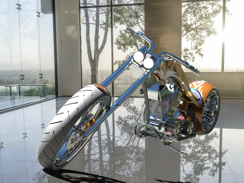
American Chopper:-
Objective:-
- The objective of this project is used to create a model of different parts of chopper using Solidworks.
- To assembled the different parts of the chopper under the Assembly environment.
- To create a photorealistic model of the chopper & Render the model using Solidworks Photoview 360 or Solidworks Visualize.
Introduction:-
A chopper is a type of custome motorcycle.The chopper pehaps the most extreme of all custome types,Often using radically modified steering angles & Lengthened forks for a stretch-out appearance.Some of characteristic fetures of the chopper are front ends with extended forks often coupled with an inctreased rack angle Frames without rear suspension,very tall or very short handlebars & larger than stock front wheels.
The first chopper were built in America & tended to be based on Harley-Devidson motorcycles,Its also littely looks like Bajaj Avenger bike.
Part Modeling:-
- Part modeling you can cretae a part from a conceptual sketch through solid features-based modeling,as well as build & modify parts through direct & initutive graphical manipulation.
Parts to be modeled for chopper:-
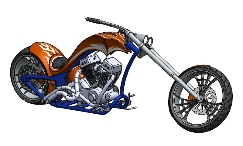
- Following parts of the chopper are modeled in Solidworks & Assembled together.
- Transmission Belt
- Front fender
- Rear fender
- Kickstand
- engine
- Oil Tank
- Gas tank
- Chain
- Chassis
- Pedal
- Front wheel
- Rear Wheel
- Front Fork
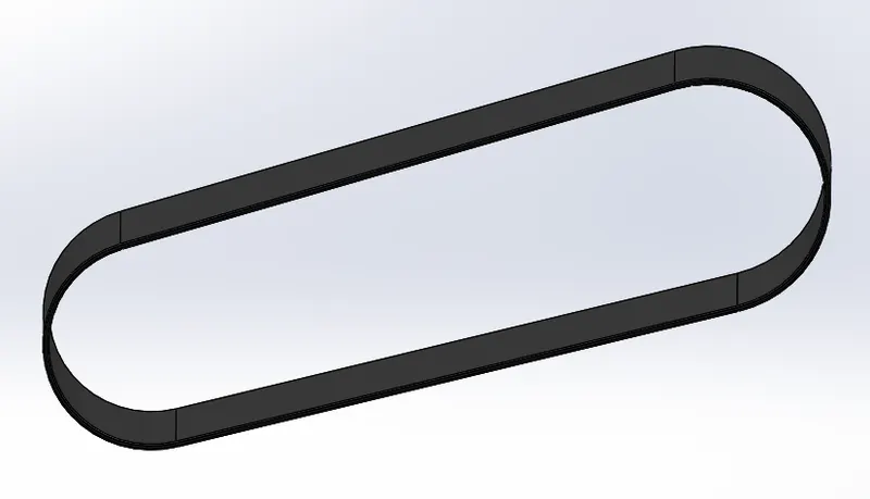
1. Transmission Belt:-
The transmission belt in the chopper is used to Transmit bthe power from the engine to the gearbox.
Command used:-
i) Sketch- It is the 2D representation with respect to the plane.In solidworks different sketch options are avai;lble such as Arc,line,circle,spline,rectangle etc..
ii)Extrude- It is used to convert 2D sketch into as 3D model.
iii) Fillet- Fillet creates a rounded internal or external face on the part,we can fillet all the edges of a face,selected edges & selected sets of face.
iv) Offset entites- It is used to create one or more sketch entities,selected model edges,or model faces by a specified distance.
v) Apperances- It is used to apply colour & optical properties to the entire part,or selected faces,fetaures or bodies.We can also kmodify the colour by manipulating the shaded apeearance of the model.
2. Front Fender:-
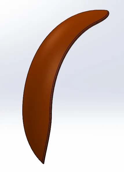
The Front fender is a part mounted on fork above the wheel to protect the rider & the chopper other parts from debries & foriegn particles.
Features used to create Front Fender-
- Sketch
- Offset entities
- Trim entities
- Revolve
- Dynamic mirror
- Split
- Appearances
i) Trim Entities- Select the trim type based on entities we want to trim or extend.All trim types are available with 2D Sketches & 2D shetches on 3D planes.We can used any of the following trim optios:Power trim
ii) Revolve:- To create a revolve features: create sketch that contains one or more profiles & a centerline,line or edges to use as the axis around whitch the features revolves.Click one of the foloowing revolve tools.
iii) Dyanamic mirror:- Dynamic mirror is the important tool in solidworks.As you sketch the entities,they are mirrored about the pre-selected sketch entity.
3) Rear Fender:-
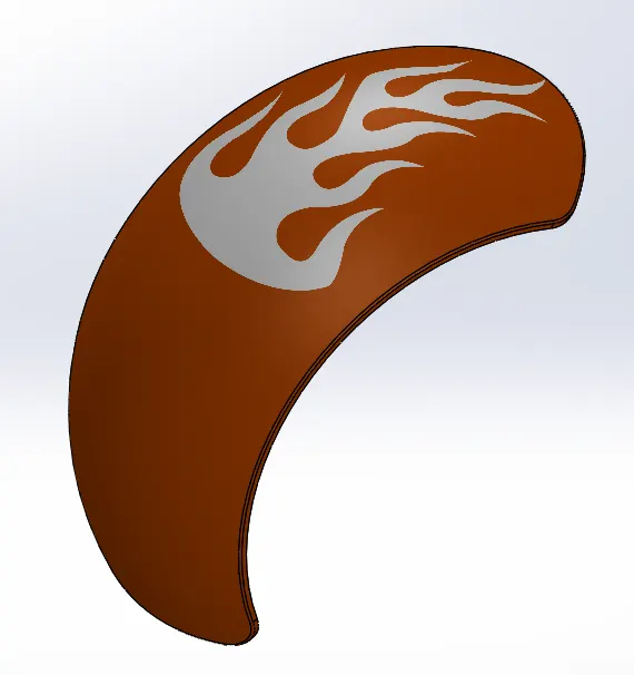
The rear fender is mounted on the chassis of the rear part above the rear wheel.
Features used to create Rear Fender-
- Sketch
- Offset entities
- Trim entites
- Revolve
- Appearances
Appearances:- An appearances defines the visual propertoes of the model,including colour & texture.Appearance do not affect on physical properties,which arre defined byu material.Every material assigned a default appearance that emulates the look of the material.
4) Kickstand:-
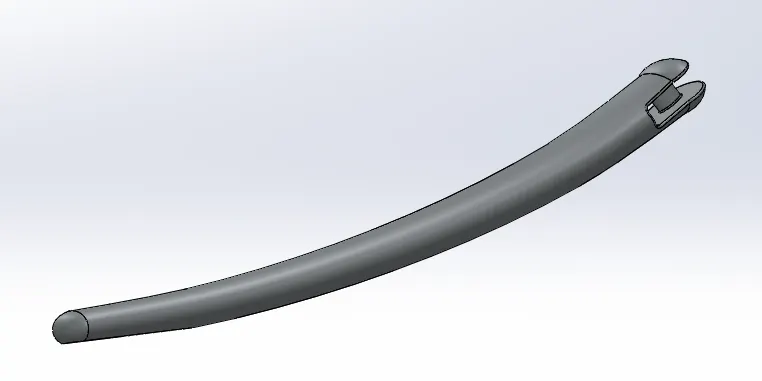
Kickstand is also known as Side stand,It is used to support the chopper.
Features used to create Kickstand-
- Sketch
- Loft
- Dome
- Extrude Boss
- Exturude cut
- Fillet
- Split
- Appearances
i) Loft:- The loft fetatures in solidworks allows you generate complex geometry in a single feature.It does this by interpolating surfaces between various cross-sections of a model.These cross-sections can be sketches ,faces,or edges.In the loft interface,these cross-sectios are considered "Loft Profiles".
ii) Extrude cut:- Extrude is another cool feature which helps to remove material from the 3D model.it is just to opposite to extrude boss ,because its cut a sketch profile while extruding. You can cut in both direction and mainely used for creating holes,channels,slots etc.
iii) Split:- The split line tools is used to project an entity onto other surfaces or curved . You are also able to split faces an multiple bodies with one command.
iv) Dome:- Select one more planer or non planer faces,we can apply dome to faces whose centroid lies outsidethe face.This allows we to apply domes to irregularity shaped counters.
5) Engine:-
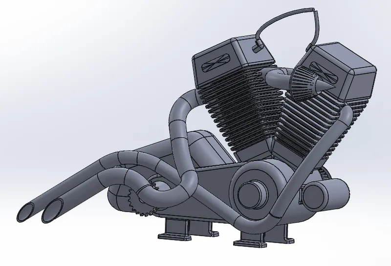
- Engine is the prime mover of the bike.The Engine converts chemical energy into heat energy & then heat energy converted into mechanical work.
- The machanical work in the engine is rotational motion.This rotation converted to the wheel with the used of chain & sprocket through the gear box & clutch.
Features used to create Engine-
- Sketch
- Trim
- Convert entities
- Revolve
- Cut extrude
- Boss extrude
- Offset
- Dome
- Fillet
- Composite curve
- Project curve
- Circular pattern
- Sweep
- Mirror
- Split
6) Oil Tank:-
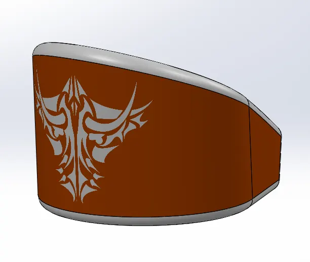
The oil tank is used as reservoir to meet the oil requirements of the engine & to lubricate the parts.It is hollow in shape.
Features used to create Oil Tank-
- Sketch
- Extruse
- Combine
- Fillet
- Shell
- Appearances
i) Combine:- It is used to combine two or more bodies.
ii) Shell:- The shell tool hollows out a part,leaves open the faces we select,& cretaes thin wall- feature on the remaining faces,If we do not select any face on the model,we can shell a solid part,cretaing a closed,hollow model.We can also shell a model using multiple thickness.
7) Gas Tank:-
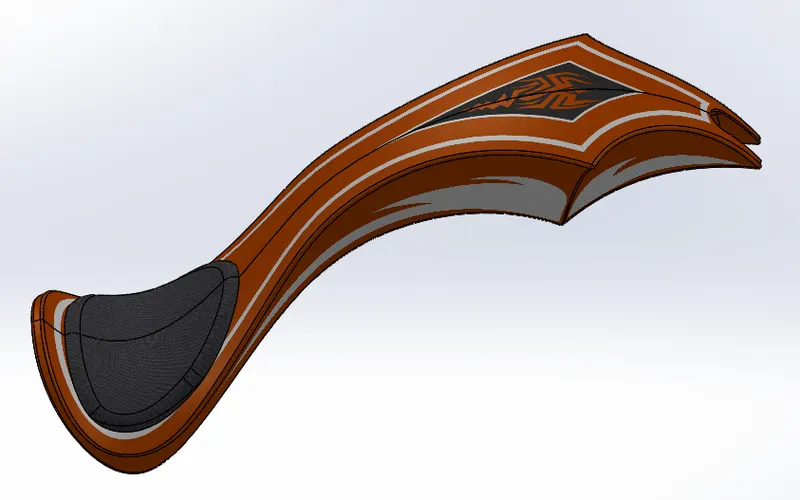
Its act as a reservoir to meet the fuel requirements of the chopper.
Features used to create Gas Tank-
- Sketch
- Trim
- Project curve
- Sweep srface
- Loft surface
- Convert entites
- Srafce trim
- Fill surface
- Knit surface
- Sweep cut
- Fillet
i) Surface trim:- Primary is used to cut away material from a surface,& provides two modes:Standard & Mutual.In standard modes ,a single slection is define as trim tool,& Target surface are trimmed accordingly.In mutual mode,multiple surfaces are trimmed with respect to each other.
ii) Fill surface:- The filled surface features construct a surface patch with any number of sides,within boundry defined by existing model edges,sketches or curves including composite curves.
iii) Loft Surface:- Loft surface are surface generated by multiple 3D curves or existing edges creating a tangency between the selected curves.
iv) Sweep surface:- Creates a surface fetaures by sweeping an open or closed profile along an open or closed path
v) Srface Knit:- It is combine to used two or more faces & surface sinto one.
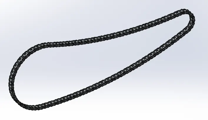
8) Chain:-
Chain drive is used for transmission of mechanical power,in this case the power from the engine to the wheels of a vehicle.
Chain drive design was a lengthy process as it required repetiton of various commands,But the curved driven pattern & mirror command in solidworks came handy in this case.
Features used to create Chain-
- Sketch
- Trim
- Fillet
- Blocks
- Extrude
- Patterns
- Appearances
i) Blocks:- We can make,save,edit,& insert blocks for drawing items & sketch that we use often,such as standrad notes,title blocks,label position & so on.We can attach blocks to geometry or to drawing views,& we can insert them into sheet formats.
ii) Patterns:- The curve driven pattern allows you to crfetae pattern along a planer or 3D curve.we can base our pattern on an open curve ,or an closed curve,such as circle.In the chain part Curve driven pattern is used.
9) Chassis:-
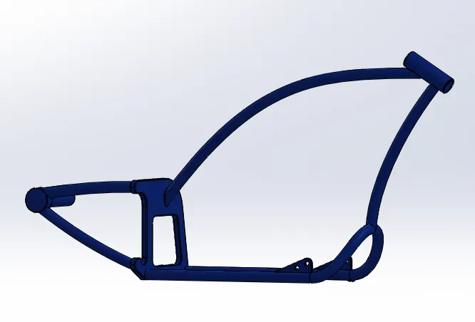
A chassis is the load bearing framework of a chopper which structurally supports its function & constructions.All the parts of the vehicles Wheels,Transmission,Fuel Tank etc..are mounted on it.
Features used to create Chassis-
- Sketch
- Offset
- Convert entities
- Project curve
- Trim
- Plane
- Sweep
- Split
- Revolve
- Cut extruse
- Fillet
- Combine
- Appearance
Convert Entities:- We can create one or more curves in a sketch by projecting an edge,loop,face,curve or external sketch contour,set of edges or set of sketch curve onto the sketch plane.
10) Pedal:-
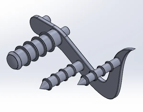
Pedal is n external part atached to the chassis.the pedal is used to place the leg on top of that.To give comfort to the rider pedal is used.
Features used to create Pedal-
- Sketch
- Fillet
- Dome
- Extrude
- Chamfer
- Linear Pattern
- Appearance
i) Chamfer:- A cut on the edge or corner of something that makes it slope slightely rather than being perfectly square.
ii) Linear Pattern:- Linear pattern create multiple instances of one or more features that you can space uniformly along one or two linear path.
11) Front Wheel:-
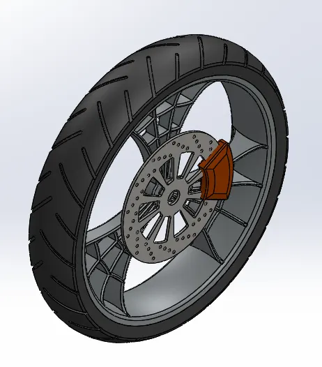
The front wheel consists of the unique spider web shaped rims,tyre,brake,rotor & caliper.
Features used to create Front wheel-
- Sketch
- Revolve
- Trim
- Fillet
- Extrude
- Revolve cut
- Linear pattern
- Chamfer
- Cut extrude
- Circular pattern
- Appearances
i) Revolve cut:- The revolved command used to cut a solid geometry by revolving about an axis,The axis may be reference axis.
ii) Circular pattern:- It is used to create multiple instances of one or mpre features that we can spoace uniformly arounf an axis.
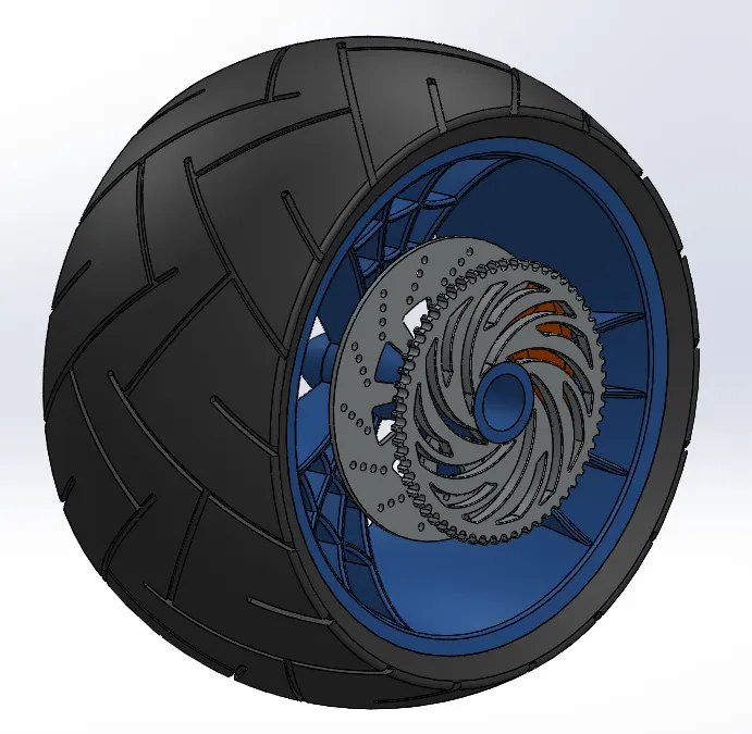
12) Rear Wheel:-
Rear wheel situated at rear portion of chassis.The rear wheel carries the large sprocket & Disc.The power is transmitted to rwar wheel from the gearbox through the chain.
Features used to create Rear Wheel-
- Sketch
- Revolve
- Trim
- Fillet
- Extrude
- Planes
- Revolve cut
- Linear Pattern
- Chamfer
- Extrude cut
- Circular pattern
- Appearance
13) Front Fork:-
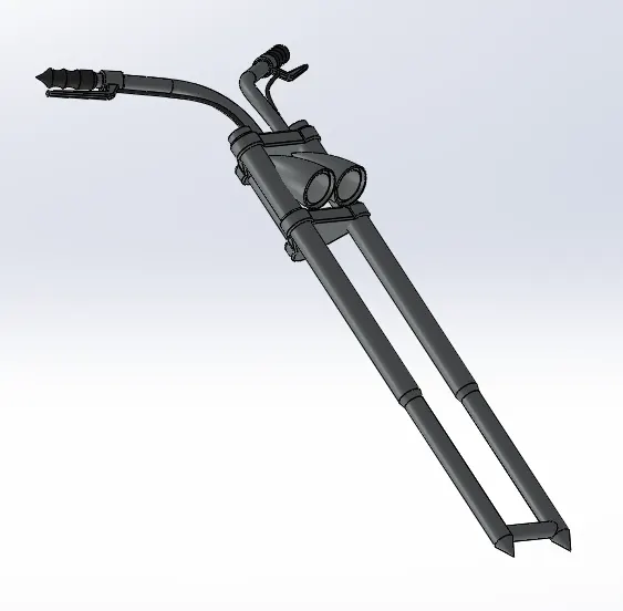
Most motorcycle used today telescopic forks for the front suspension.The forks can be most easily understood as simply large hydraulis shock absorbers with internal coil springs.They allow the front wheel to react to imperfections in the road while isolating the rest of the motocycle from that motion.
Features used to create Front Fork-
- Sketch
- Extrude
- Trim
- Revolved
- Split
- Plane
- Convert entites
- Move/Copy
- Dome
- Mirror
- Combine
- Project Curve
- Sweep
- Appearance
i) Mirror:- Mirroring is another way that solidworks can create a copy of an existing object.Additionaly,We must choose a plane to mirror parts.In most cases.We need to create our own plane to have the mirror done the way we need.
ii) Project Curve:- A projected curve is typically used either in sweep or loft as path or guide curve.They are made by using two sketches to a singke curve or use a sketch to project on surface.
iii) Move or Copy Body:- Using the command we can move,Rotate & copy solid surface bodies or place them using the mates.
iv) Sweep:- Its used to create solid features by sweeping a closed profile along an open or closed path.
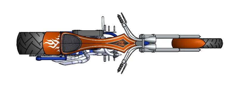
Assembly of Chopper:-
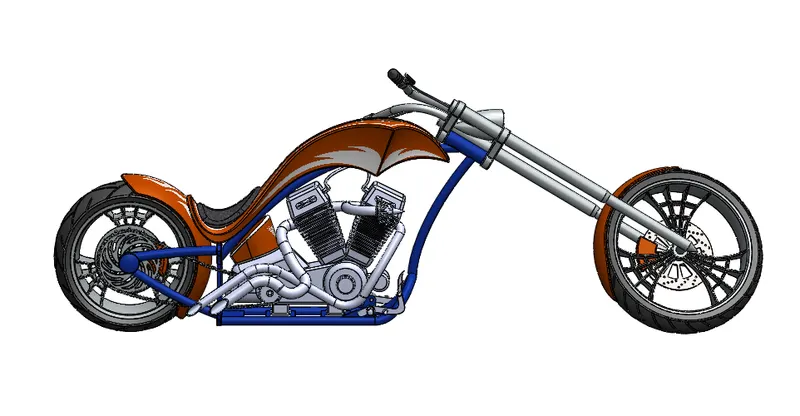
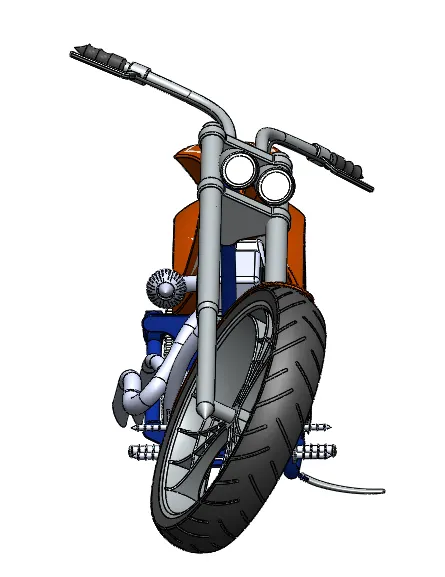
- Intially,chassis part is inserted in the assembly by using insert part in the option.After that the part is inserted in the assembly environment & clicked ok to fix the chassis.
- After that the other parts of the chopper are inserted into the assembly & given possible mate condition.
Features used to Assembly Chopper-
- Mates
- Insert Part
Mates:- Its create a geometric relationship between assembly components.As we add mates,we define the allowable direction of the linear or rotational motion of the components.We can move a components within its degree of freedom ,visualizing the assembly behaviour.
Front View-
Side View:-
Isometric View:-
Top View:-
Camera View:-
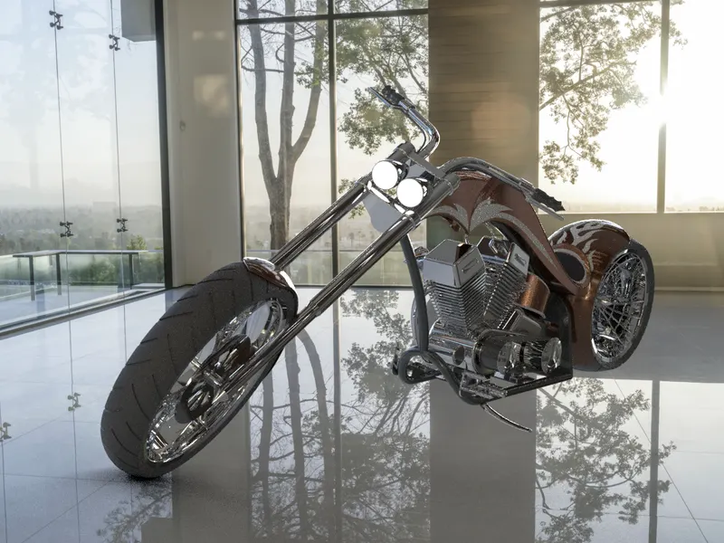
Photorealistic Rendering Of Chopper:-
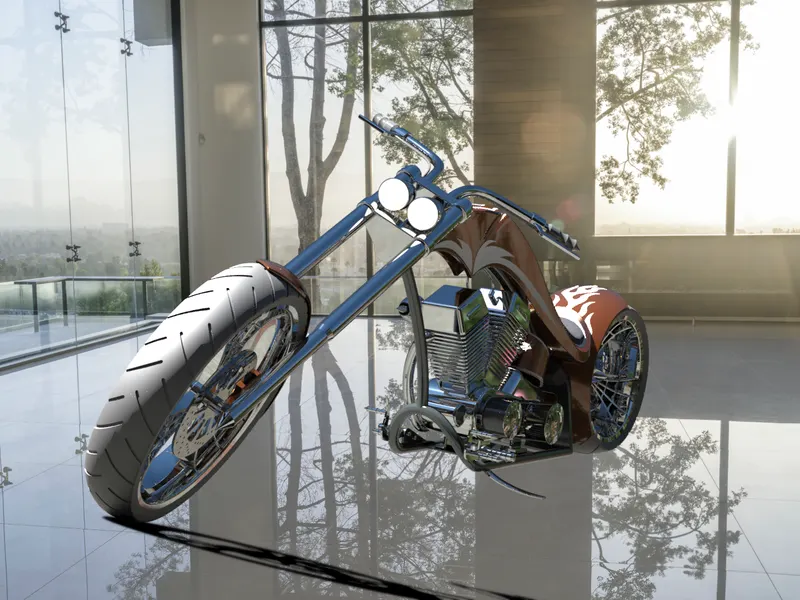
- Rendering is the process of creating realistic images of the photorealistic model with the environment ,renedering has been done in two ways in solidworks.
1) Photoview 360
2) Solidworks Visualize
- In the photorealistic model,same of the mate condition & positions are changes to render realistic models. Then the photorealistic model is rendered into realistic images with different views.
Conclusion:-
- All the exterior part of the chopper are modeled successfully under soildwroks modeling environment.
- All the parts are inserted into the assembly environment & the chopper is successfully assembled.
- The photorealistic image is successfully rendered with the use of Photoview 360 & Solidworks visualize.