Radar Mast & Final Assembly of Yacht
Sunseeker Predator Yacht Project
Introduction:
This project report explains the overall designing interfacing that has been used for the designing, creation and assembly of the Sunseeker Predator Yacht. This yacht is divided into various parts from smallest and easiest designing steps involving propeller, radar to the complex and mind-boggling designing steps involving the hull, Superstructure. We are going to see the various commands used under various material creation feature like solid and surface model like propeller, radar mast that are created using solid modelling features and bodies that were created using surface features and then convert into solid models to use features like mirrors and etc.,
Objective:
The main objective of this project is the creation of the Sunseeker Predator Yacht Model. To achieve this objective, we need to create individual components of the said yacht that we need to assembly to create resultant model "The Sunseeker Predator Yacht". To achieve this complete this project and create to assembly the resultant yacht model we need to follow the dimensions issued in the blueprint under the units of "Millimeters, Grams, Seconds (MMGS)".
Designing methodology:
Parts modelling:
The part designing methodology used in the creation of the parts differs with the specification. As mentioned in the introduction is that simple parts like the propeller, radar are created using the solid modelling feature and extremely complex models like the hull, superstructure were created using the surface modelling and then converted into solid model.
Solid modelling:
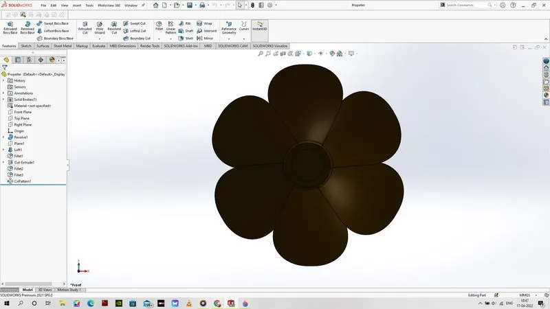
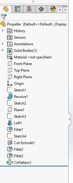
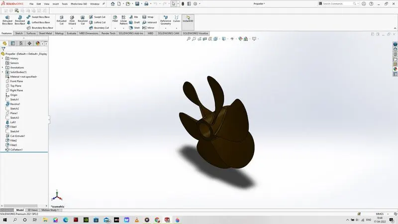
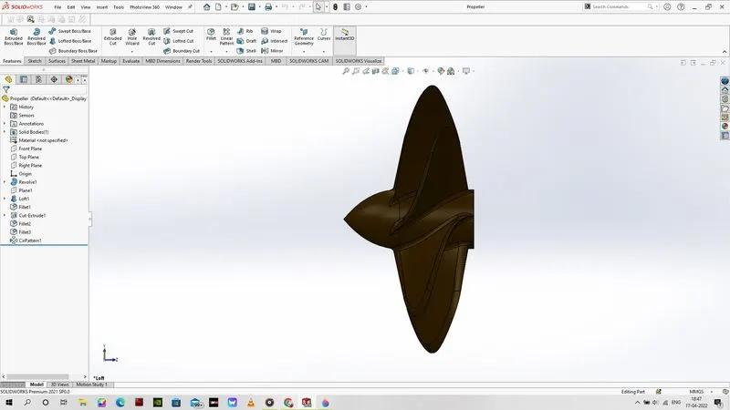
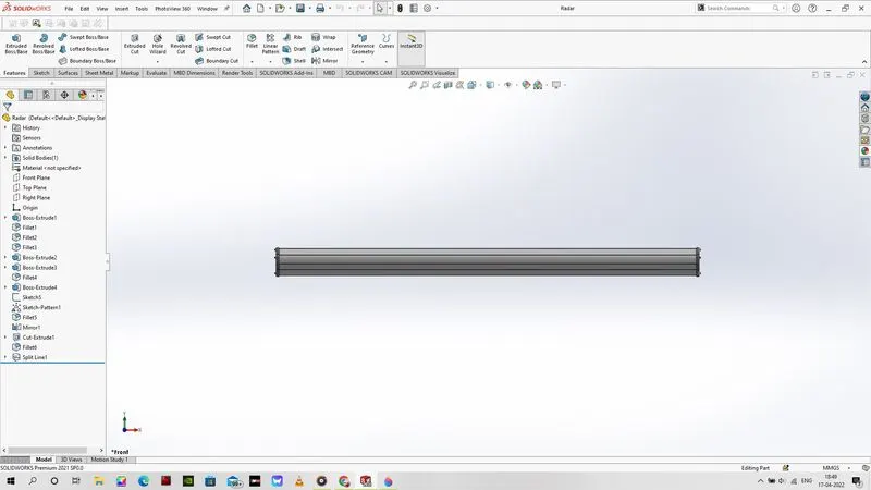
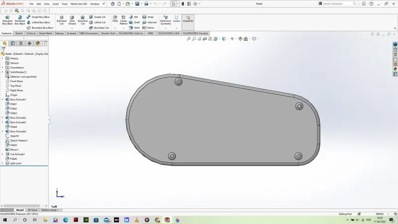
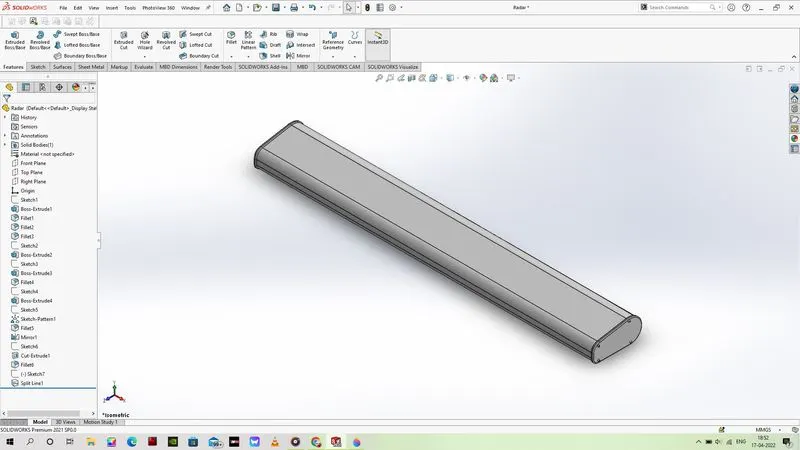
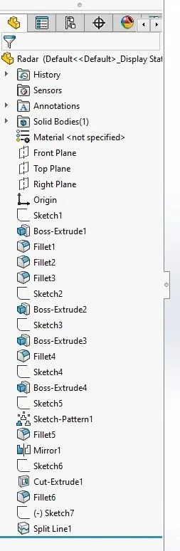
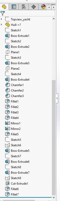
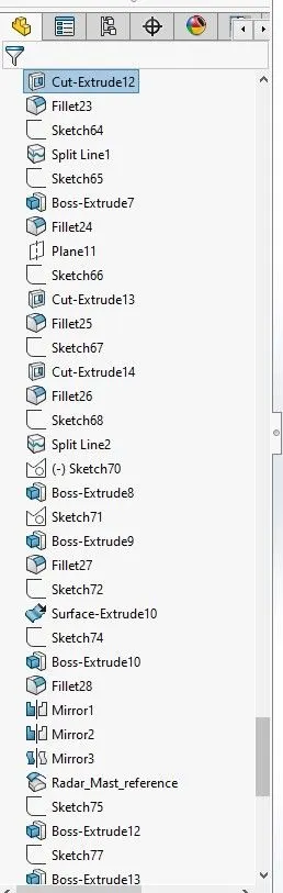
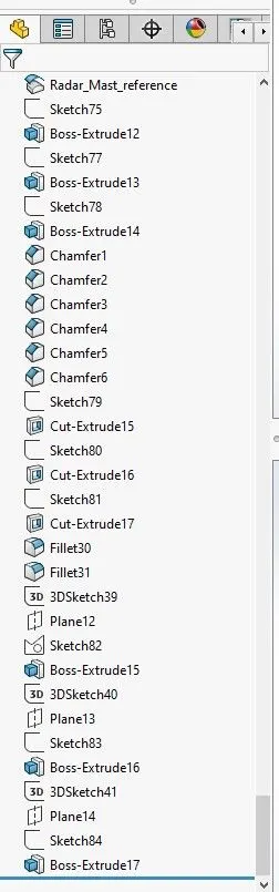
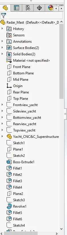
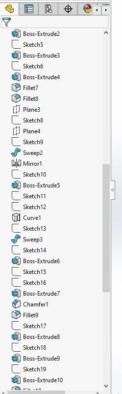
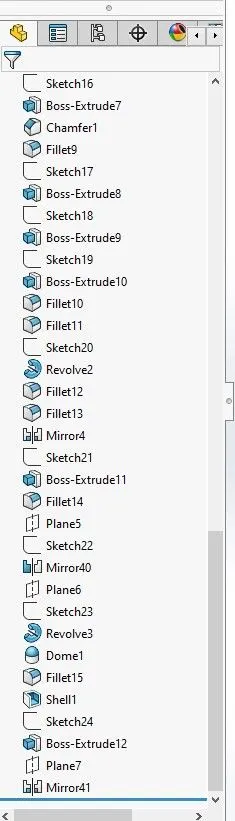
First, we will go through some of the solid modelling features that used for the creation of models that are created only and directly using the solid features. Parts like propeller, radar are created with the help of solid model creation feature. We will see the solid features that were used in the creation of the propeller, radar model with the help of flow-chart.
Surface Modelling (Hybrid Usage):
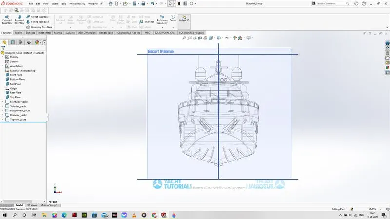
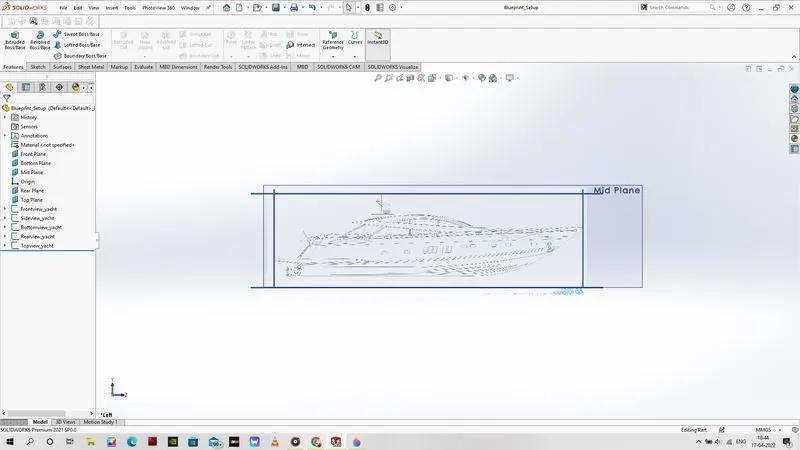
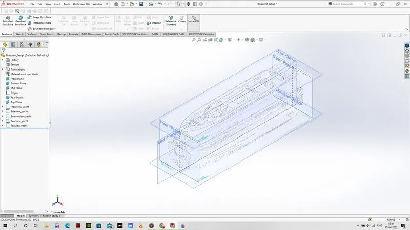
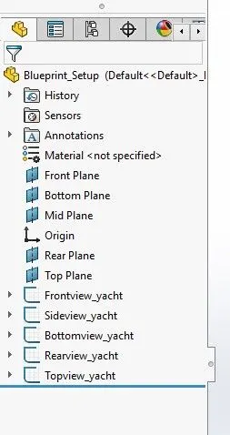
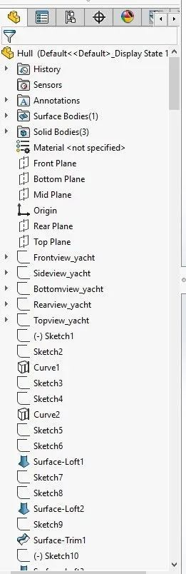
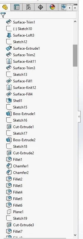
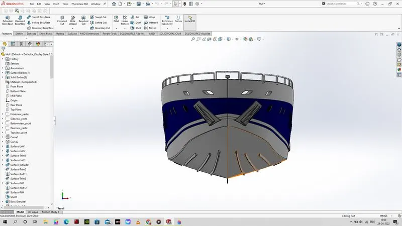
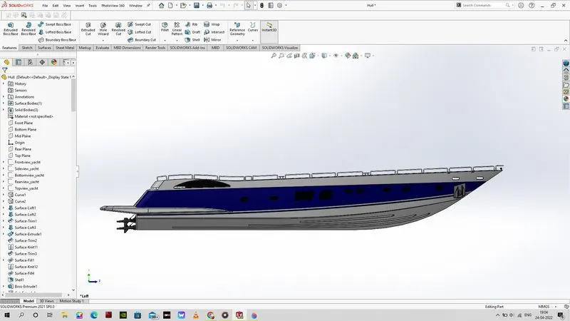
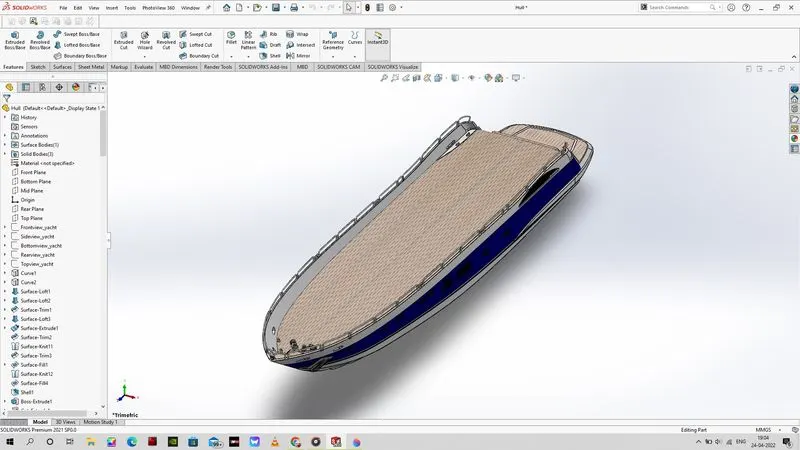
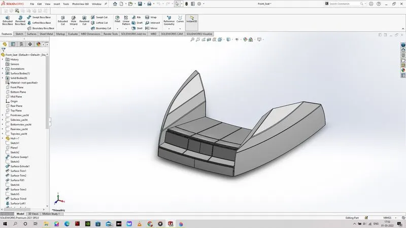
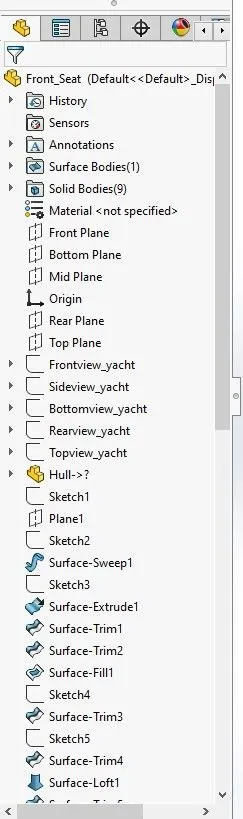
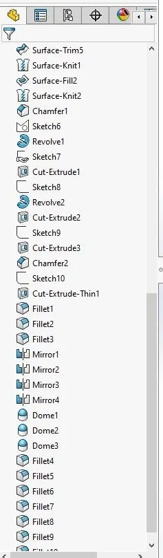
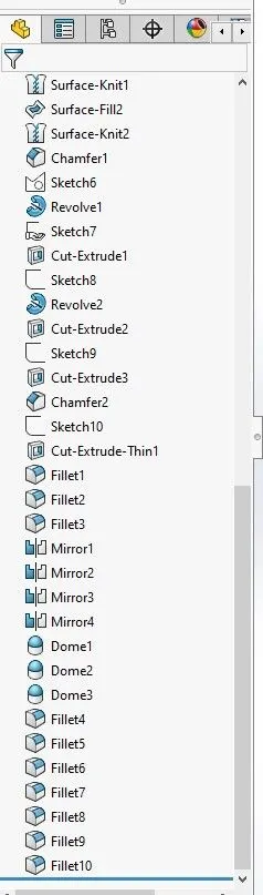
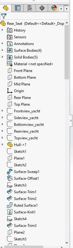
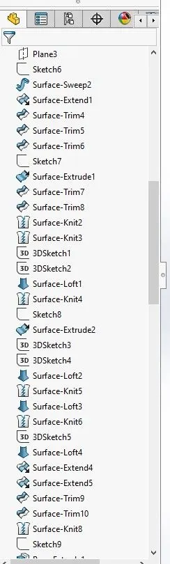
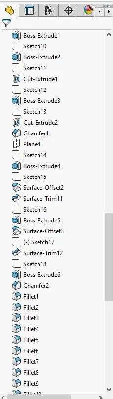
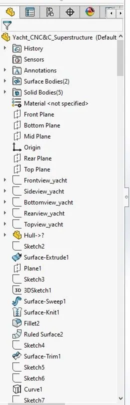
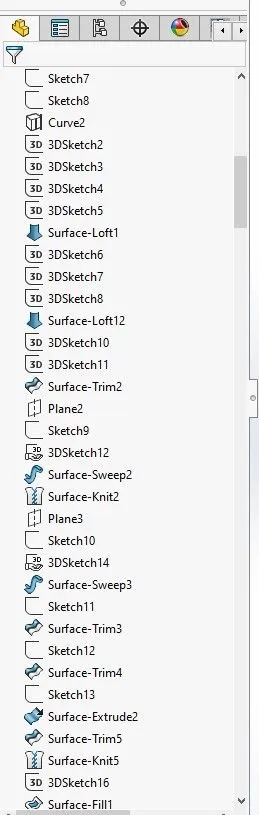
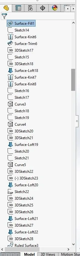
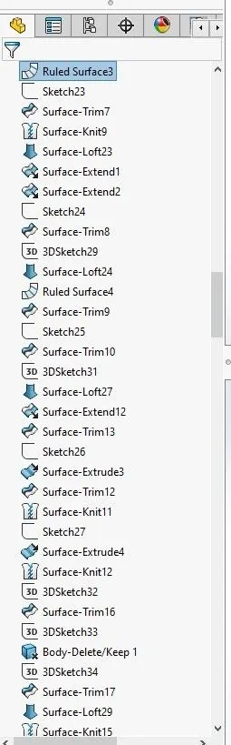
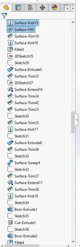
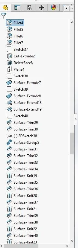
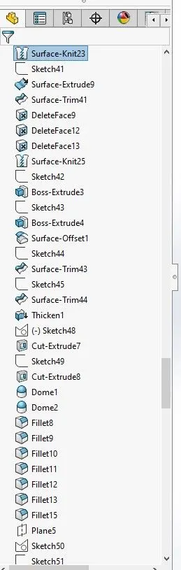
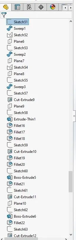
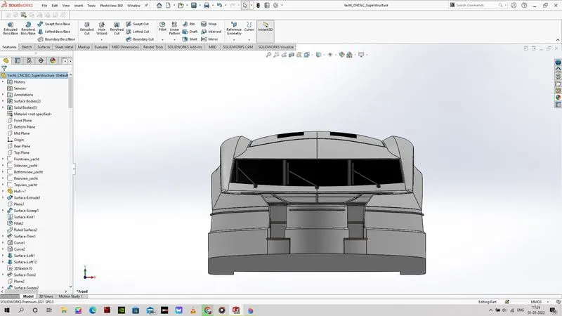
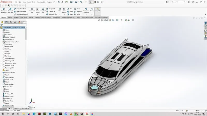
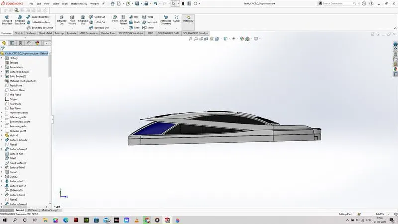
The models that were created using hybrid command features like the surface and then converted into a solid model for various commands like mirror, fillets, chamfers. The model of hull (base part in assembly) is created by command features like project curve, loft surface, extrude surface, filled surface, etc. This model is created with reference to the sketch images that we have placed in the blueprint parts.
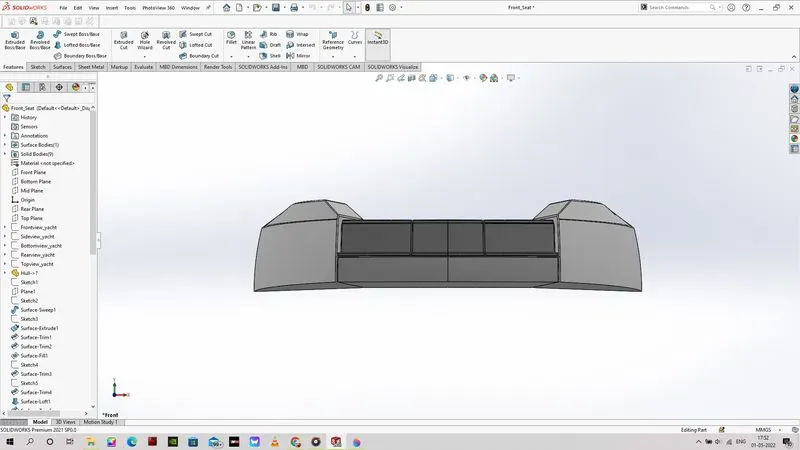
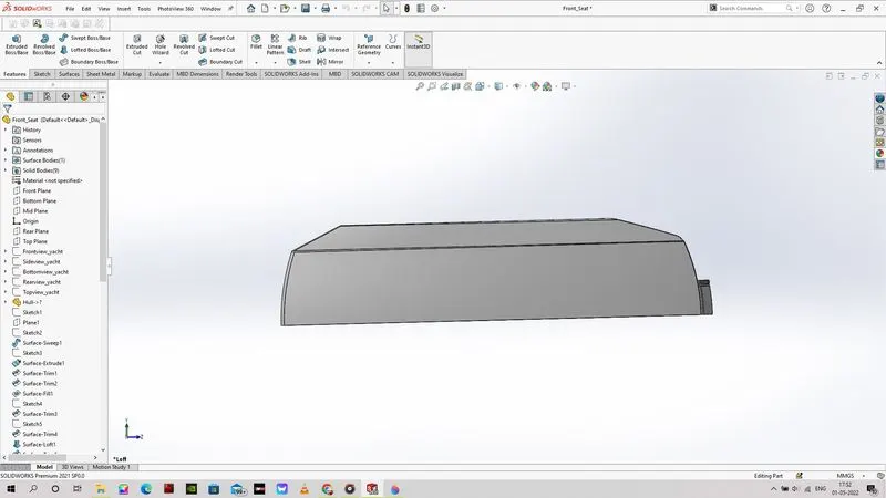
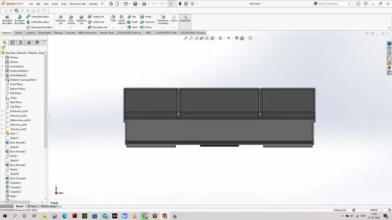
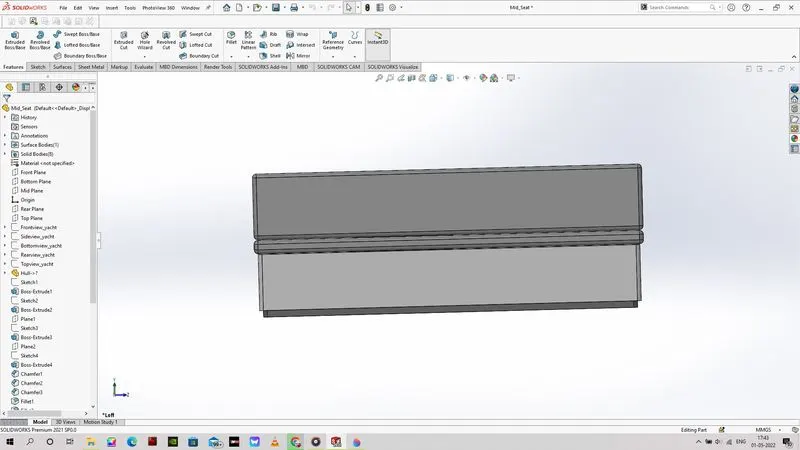
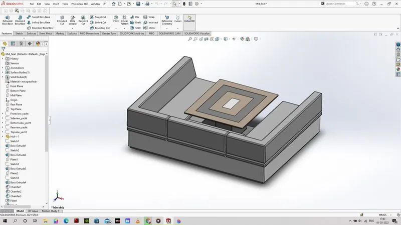
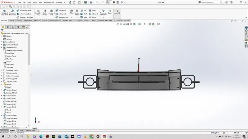
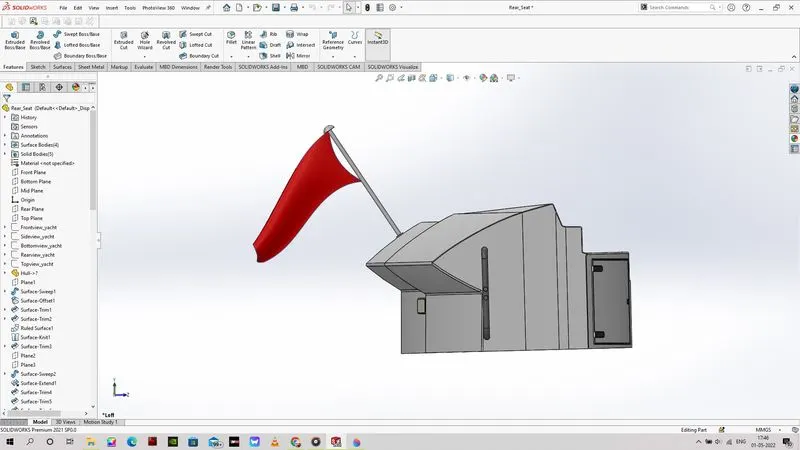
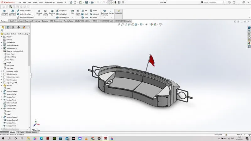
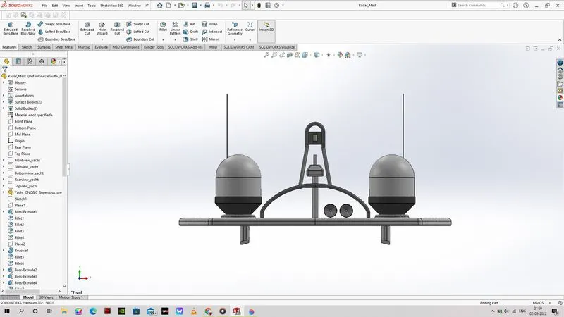
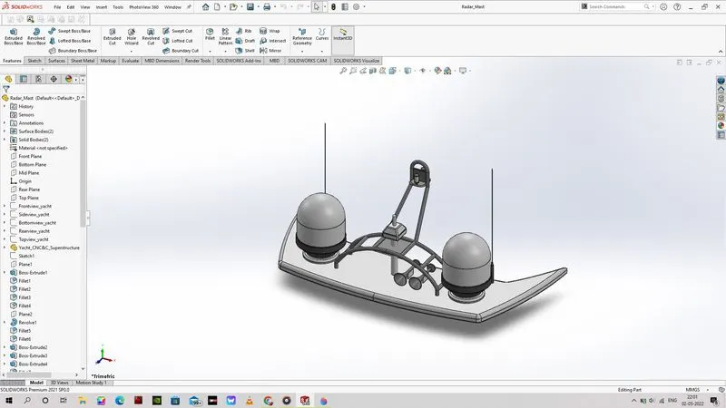
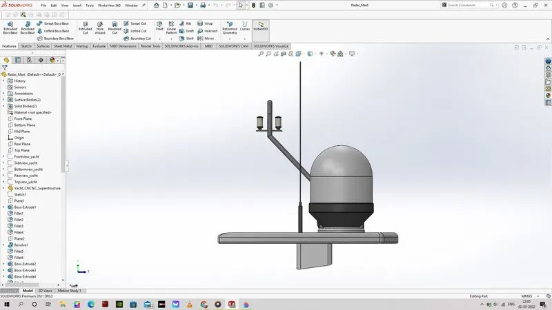
The models like the hull, front seat, middle seat, rear seat, superstructure, radar mast are created using the blueprint setup file. Then the curves and the outline will traced out in to phase and then they are projected with the help of the project curve feature. These curves are used to create a surfaces using the loft surfaces command. Once all the required surfaces are created in the required shape. We can use knit surface command to knit and merge these surfaces and create a solid surface.
Assembly:
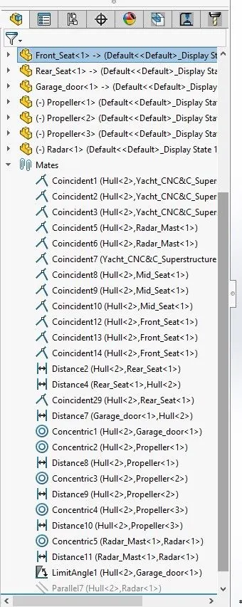
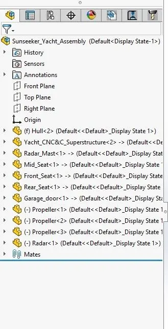
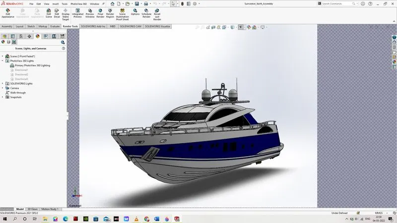
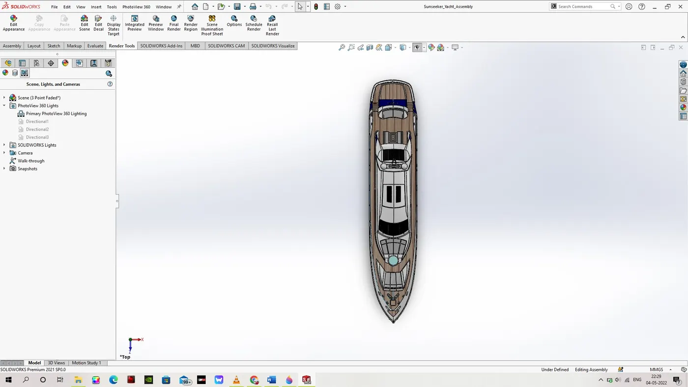
The design methodology use for the assembly of this sunseeker yacht model is bottom-up assembly method. The Hull part is used as the base model and the assembly order is as follows.
- Radar Mast.
- Front Seat.
- Middle Seat.
- Rear Seat.
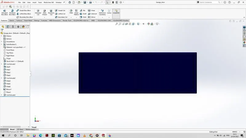
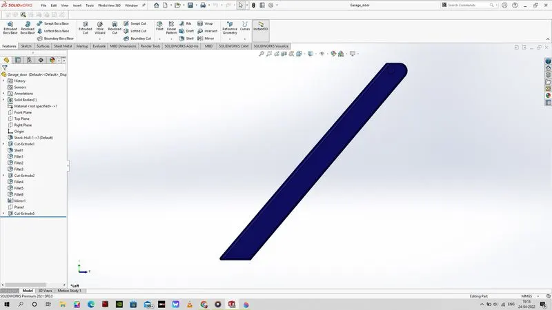
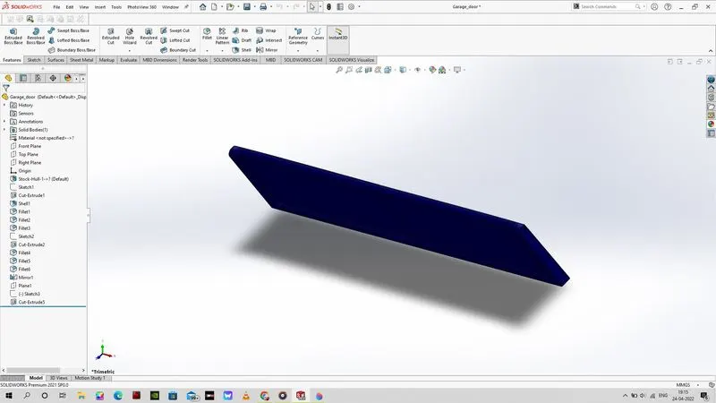
- Garage Door.
These part are assembled in the order mentioned above to create the assembled model of the Sunseeker Predator Yacht Model. The base part was used as reference to place and lock all axis movement for the other components. The reference planes that are commonly used in the assembly are front and right plane in this assembly model.
Features/Commands:
As mentioned in the previous parts of the report that both the surface and solid features are used in the creation of the model/parts that were used in the assembly of the Sunseeker Predator Yacht. We will see some of the features that were used for the creation of these model/parts.
Features Commands Used:
Some of the features that were used for the creation of parts are as follows.
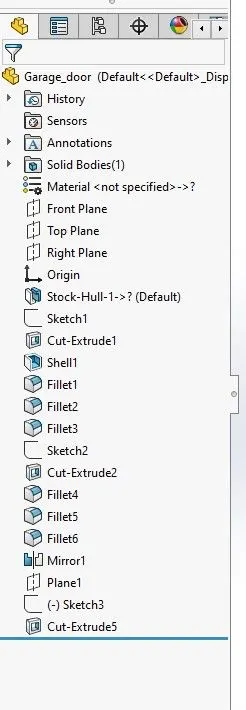
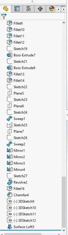
- Extrude Boss/Base: This command is used to create solid bodies from closed sketches in the direction that perpendicular to plane/reference used for the creation of the said sketch. The user needs to define the distance of extrude, or user can use options like up to next, up to body, up to surface, up to vertex, midplane options to create the required object for the part. There is also a merge results option to combine or not combine the said created object.
- Revolve Boss/Base: This command is used to create solid bodies based on the axis of revolution defined by the designing/user. The angle of revolution can be set by the user as required. I used this angle of revolution option while creating a light bulb in the radar mast part. I used 180 deg as angle of revolution to create one half of the required model so the other half can be created using mirror option.
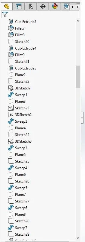
- Swept Boss/Base: This command is used to created an object/model for the part by using a sketch in a line of path that is defined by another sketch. This works with the support of these sketch to create these solid models. Typically, the path sketch is created first and the profile sketch is created in relation with the path sketch. I created the hand rail in the hull and superstructure.
- Loft Boss/Base: This command is used created solid model in reference with the sketch and in this option guide sketches are optional and user can define the sketch if required. This command creates solid object like connecting two closed sketches that are apart a certain distance in the same direction with or without angle inclination. This command was used to created the fins in the propeller.
- Fillet: This command was used to rounded corner in the required places as against to sharps edges as rounded edges have more stress resistance than the sharp edges.
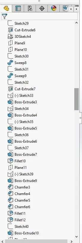
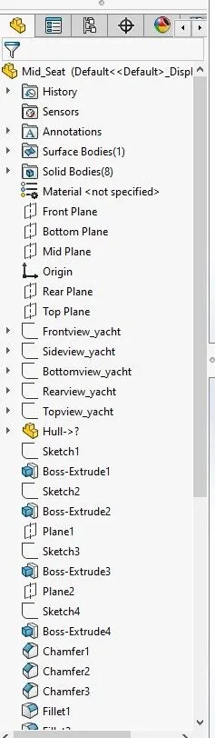
- Chamfer: This command was used for creating slanted edges in place of the sharp edges as required. This command was used based on the angle*distance, distance*distance options. This was used to create various slanting edges in radar mast, front seat parts.
- Mirror: This command used in lot of parts of the yacht. Because these parts are created on one side and then mirrored to the other side in relation with the midplane as I used the midplane as instructed in the blueprints.
- Plane: This command is used to create new plane in reference with old planes or existing planes for loft or other purposes, lines/curves and their endpoints for doing sweep and other purposes.
- Project curve: This Command is used to project curve from sketches at the meeting point of these two sketches. Example one sketch at the top planes and one sketch on the right plane will create a project curve that the meeting point of these sketches. To create a projected curve, user needs to create the required sketches in perpendicular planes so the two sketches can form a right angle.
- Extruded Surface: This command is similar to Extrude boss/base but is used to create surfaces from open and closed sketches.
- Loft Surface: This command is used to create surface between edges, profiles based on the edges or user can also define guide curves to create the joining surface in the required path.
- Ruled Surface: This command is used to create surface from existing edges at required directions. There are normal, perpendicular, tangent, angle defining options in this feature command.
- Trim Surface: This command is used to trim unwanted surface sections that we can keep the required parts of the surface that we have created. Trim tools that the used is going use should need to have interference with the surface that we are going to trim.
- Extend Surface: This is the opposite command of the trim and can be used to extend existing surface to required lengths. This command is used to used to created better intersection with the surface that we need to close to knit them together after trimming the unwanted parts of the extended/existing surfaces.
- Offset Surface: This command is used to offset existing surfaces to create new surface in perpendicular direction of the existing surfaces.
16. Filled Surface: This command is used to fill the open space between surface to create a closed object which can knitted together to create solid bodies. This command is used to create the surface in relation with edges of the existing surfaces.
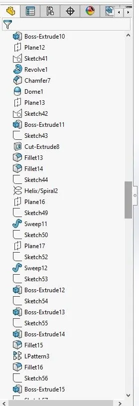
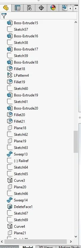
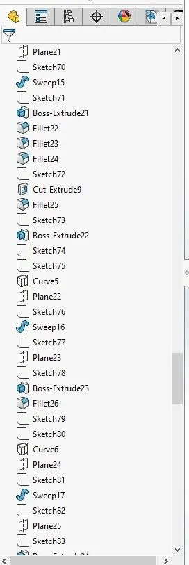
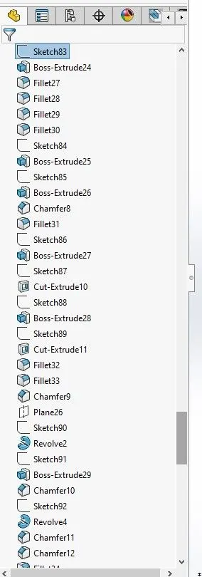
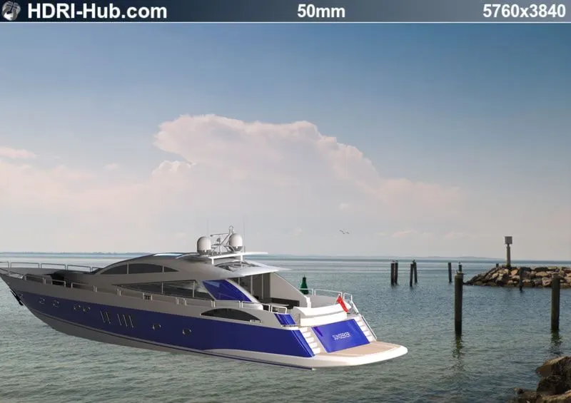
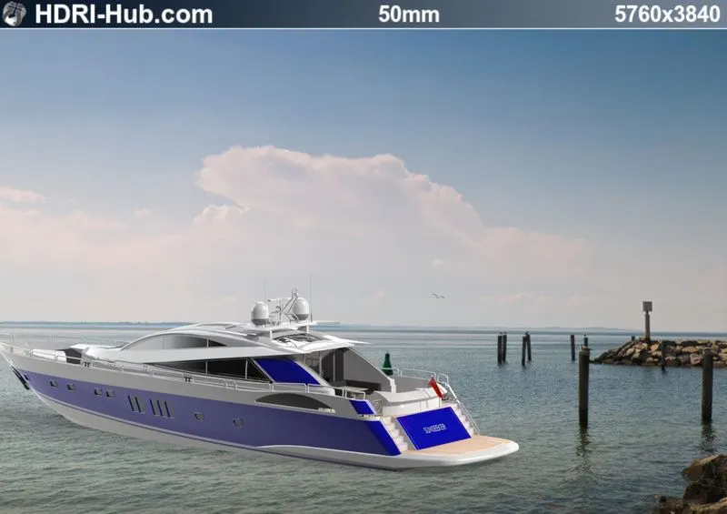
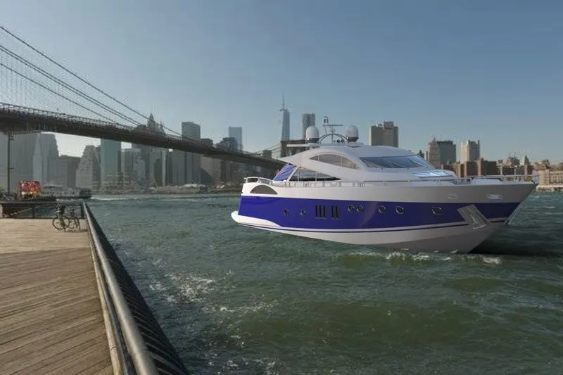
Conclusion:
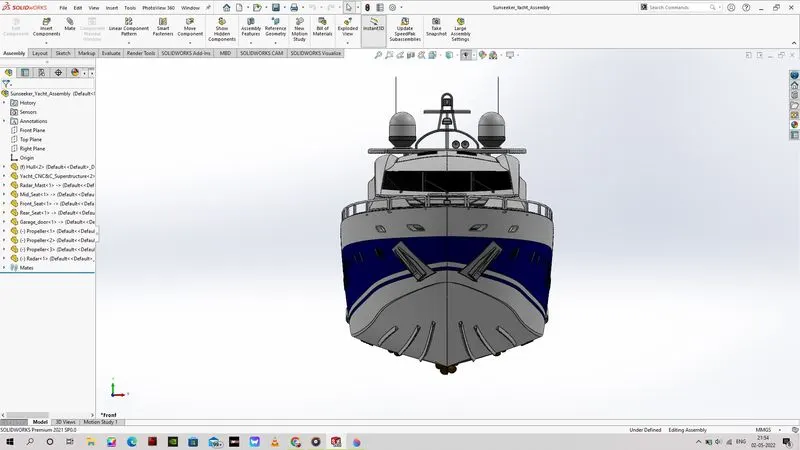
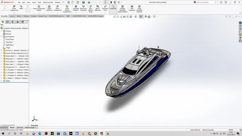
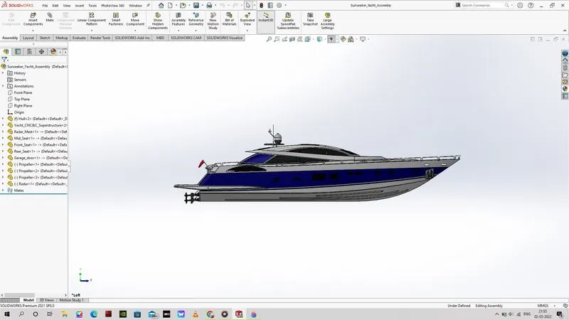
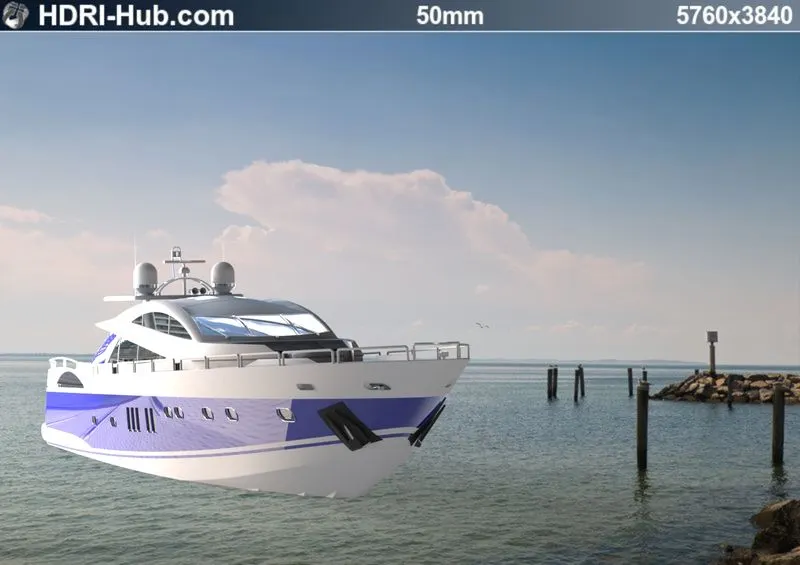
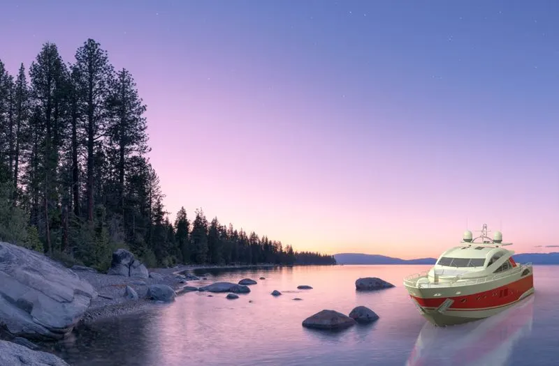
This project report of the Sunseeker Predator Yacht explains about the commands that were used in the creation of these parts through solid and surface features and the method of assembly used to assemble these components to achieve the objective of creating the yacht with the necessary and instructed dimensions and dimensional units. These render images are obtained from the hdri website. reference:https://www.hdri-hub.com/hdrishop/backplates/images/item/593-backplate-image-loc00205-plate-4-2996.