Photo Realistic Rendering
American Chopper Bike.
Introduction:
This project report is regarding the activities that are done in the creation, modelling, assembly and rendering of the model of American Chopper bike in accordance with strict instructions and measurements. I have used the same units of measurements as used in the template that is created for the designing of these model. Various feature and sketch commands have been used for the creation of this American Chopper Bike model.
The American Chopper Bike has been modelled, assembled using the solidworks 2021 design 3DCAD software and the rendering of the Same Chopper model was done with the use of Solidworks Visualize 2021 photo-rendering and animation software.
Objective:
There are two main objectives for this project.
- The main objective of this project is to learn the creation of the American chopper bike model by using sketching, solid and surface modelling.
- The other main objective of this project is the creation of the chopper bike with accordance of information gathered under guidance of the blueprints.
Chopper Parts:
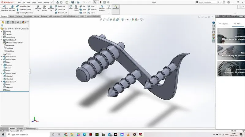
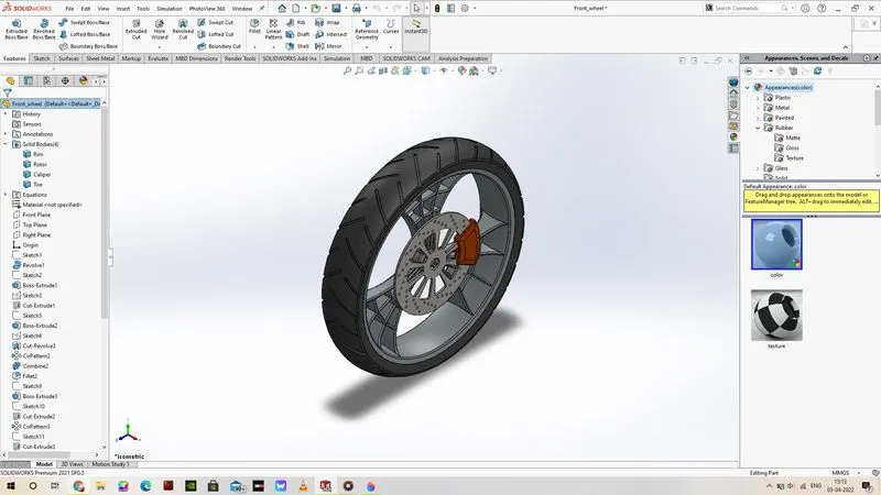
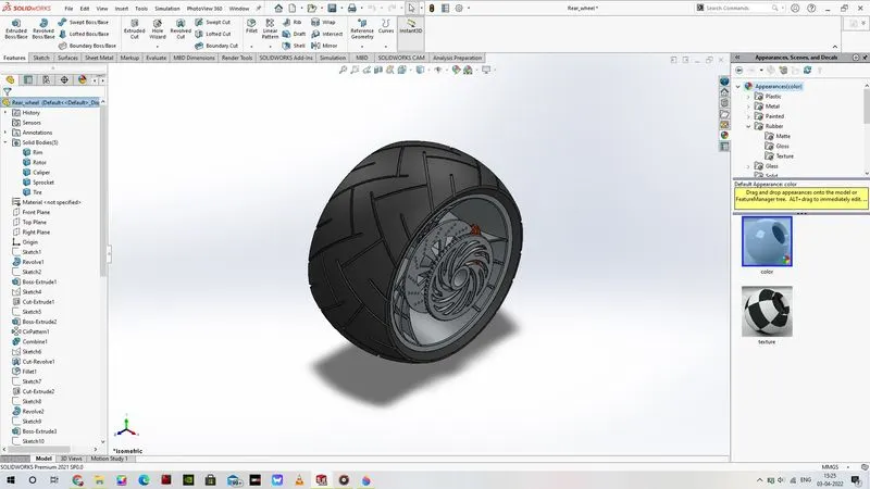
The American Chopper bike is designed using the following measurement units. The units that are used are denoted in the MMGS (Millimeter, Gram, Seconds). This 3D models of the parts of the American Chopper bike has been created in the Solidworks 2021 3DCAD design software.
The American Chopper Model consists of the following list of parts. The list of parts are as follows.
- Transmission Belt.
- Kickstand.
- Front Fender.
- Rear Fender.
- Chain.
- Oil Tank.
- Pedal.
- Front Wheel.
- Rear Wheel.
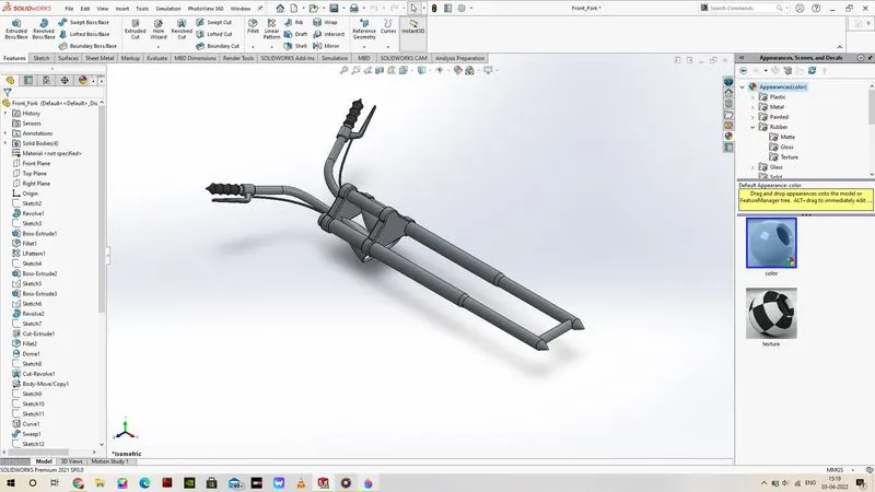
- Front Fork.
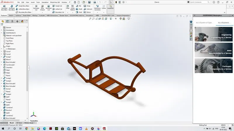
- Chassis.
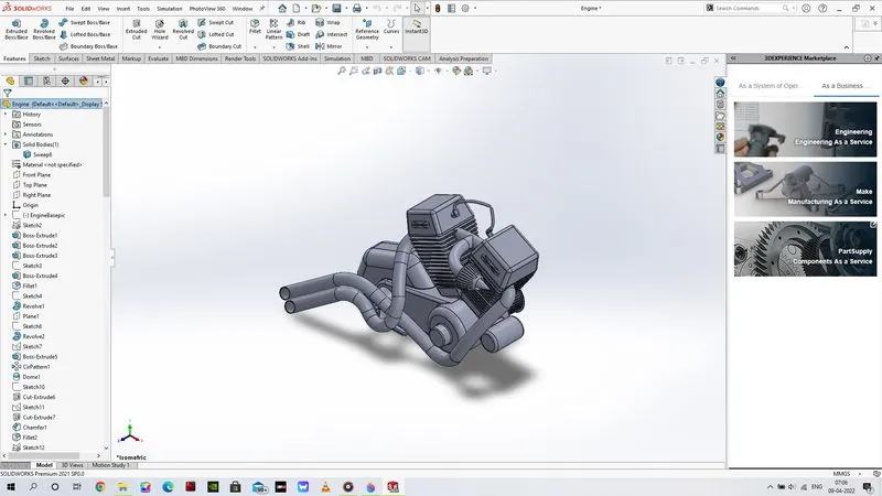
- Engine.
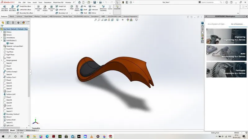
- Gastank.
Chopper Assembly:
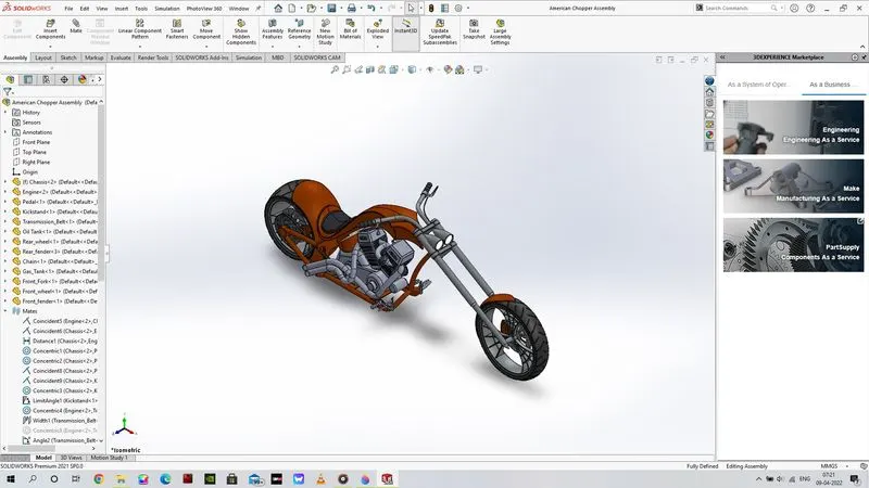
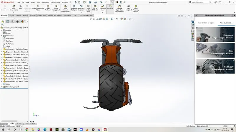
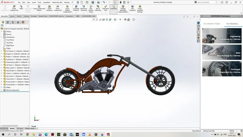
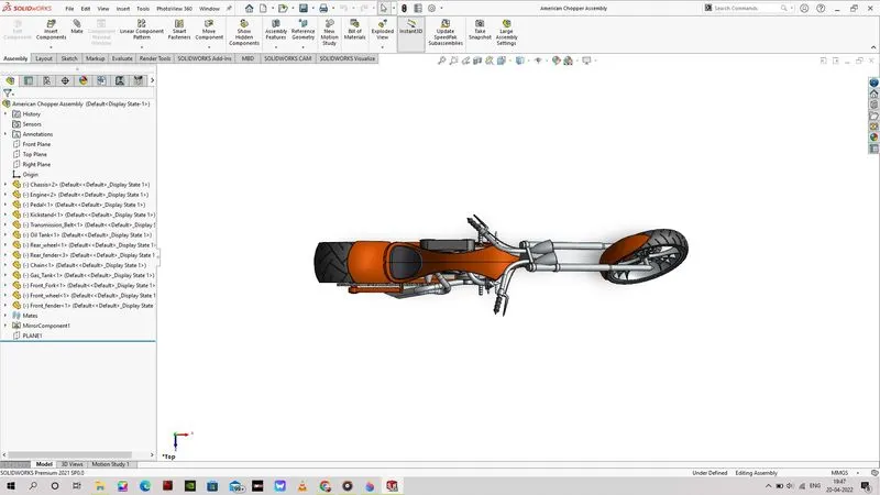
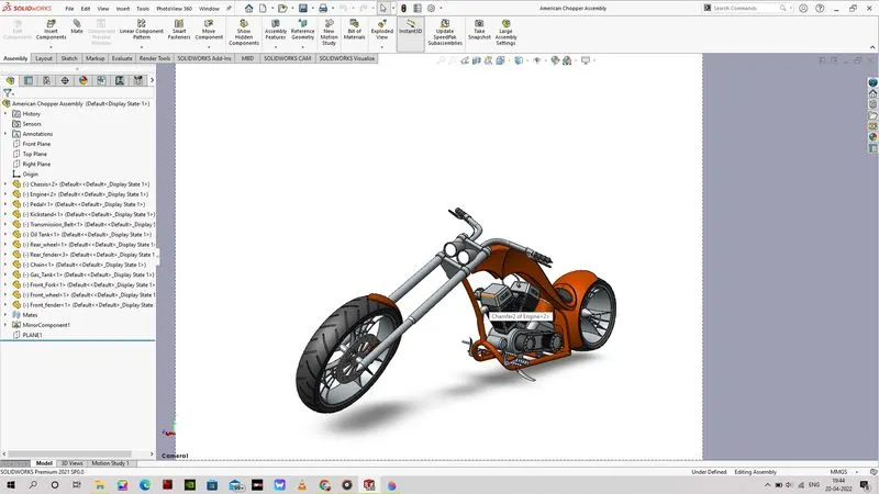
Chopper Bike Assembly was done after the creation and modelling of all these parts using the measurement provided in the blueprint for the creation of these parts. The Chopper assembly was completed and the entire model is created in a way which will resemble the chopper is shown in its resting position and lean on the right side on its kickstand (if viewed from the front end of the completely assembled Chopper model).
Chopper Rendering:
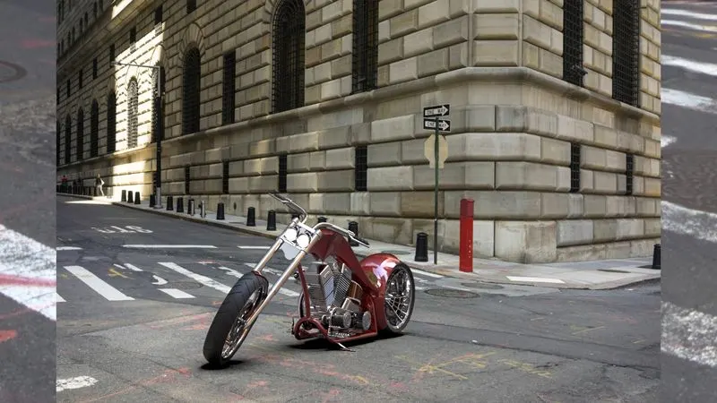
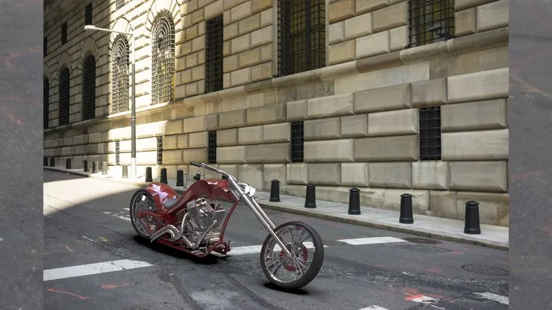
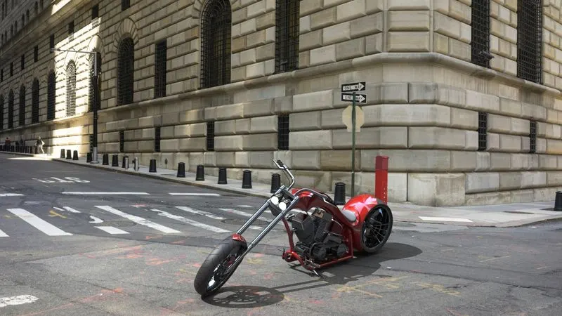
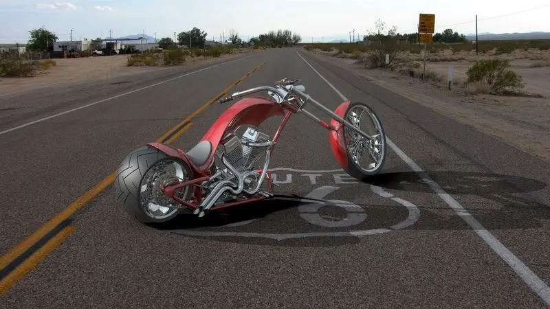
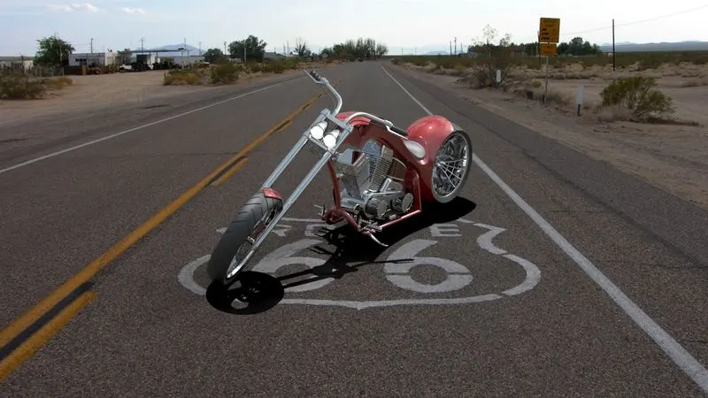
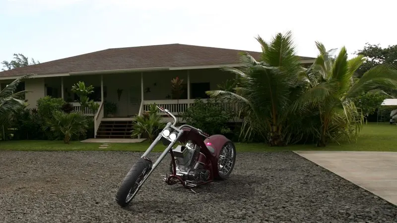
After the Chopper assembly has been completed. I need to project the chopper to resemble that it is in rest position and lean on to right side (on its kickstand). After the projection creation has been done, the solidworks visualize 2021 photo-rendering and animation software was used to do the photo realistic rendering of the American Chopper Bike.
Design Methodology:
This Modelling of the American Chopper has been done using both the solid and surface features. The Common platform is the sketch creation feature used in all the parts. The parts of the American Chopper model was created by using Extrude, Revolve, Sweep, Loft, and Surface feature commands.
Some of the commonly used commands under the sketch tab are line, spline, smart dimensions, mirror, fillets, circle and etc.
- I have used various feature commands such as Extrude, Revolve, Sweep features under the solid model tab (Feature Tab).
- I also used feature like extrude feature under the surface tab for the creation of the Gastank model which was created by using surface feature commands and converted into a solid model.
The design methodology of these parts are demonstrated with the help of these flow charts of these various parts. For the producing a proper explanation of the use of the design methodology in the model of these parts, multiple parts have been explained with the use of the flowcharts.
- Part Creation:
This part of the Chopper has been created using the extrusion design methodology.
- The Sketch is created by using the respective plane with the dimensions provided in the blueprint of the part.
- Once the sketch was fully defined, feature command is used for the creation of the solid part of the transmission belt.
- After feature command is used to create the required solid or surface model objects. Additional feature creation can be done using the required commands.
- For example: front fork is created in different section which is separated into two different sections. One is the fork and other is the handle bar. Fork is created by sketching the required model and then revolved into an object and then the axle is extruded from the fork while merging them both.
- The handle bar is created with relation to the fork, but the feature used is extrude and then linear patterning the created handle bar. After this step sweep feature is used to create the curved handle bar object.
- Further, the handle grip is created using the revolve feature. After these model creation is completed on one side. The model is mirrored to the other end and the remaining operations like fillet, chamfer, and other process are completed.
- This type of commands differs between other part like Gastank which is created using surface features and then convert into a solid object (model).
- For some parts like Gastank, surface features like trim, knit, extrude surfaces are used. Since the model is created using project curves and surfaces and after completed one side the mirror feature is used to complete the object, the overall object is merged and then converted into a solid object. Then the shell command is used to create empty tank. After then fillets and other commands are added to the parts to create and model the required end object.
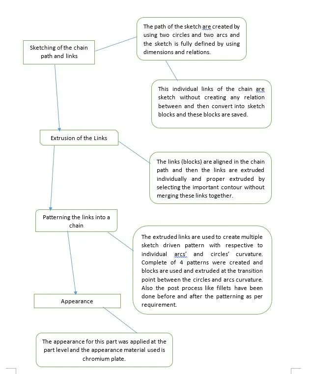
- Whereas as other parts like chain are created using the sketch driven pattern features. Complicated parts like chassis and engine uses where extrude, sweep, loft and other features.
- Once the part is completed. Appearance is defined to the parts. For the model part, its appearance material is provided in the blueprint.
- Assembly design methodology:
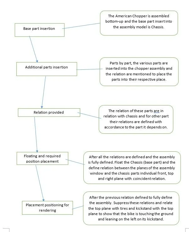
The assembly of the American Chopper is done using the Bottom-Up assembly method.
- The Bottom-Up assembly method is used for the complete assembly of the Chopper bike model.
- The Chassis is used as the base part in the assembly of the chopper. Then the parts are assembled in the following order.
- Engine.
- Pedal.
- Oil Tank.
- Chain.
- Rear Wheel.
- Front Fork.
- Kickstand.
- Transmission Belt.
- Front Wheel.
- Gas Tank.
- Rear Fender.
- Front Fender.
- Rendering Methodology:
The rendering of the American Chopper is done with support of the solidworks visualize 2021. The rendering process is done by import the solid assembly model into the rendering software and then various paint changes are done to certain parts of the chopper. After this, the HDR environment and its backplates are chosen respectively. The lights are added for specific purposes. After all the required changes and commands/features have been added. We can render the images by using into their required formats. I have used the JPEG format for the images to be saved.
Flow-Chart (Part Creation):
Flow-chart (Assembly):
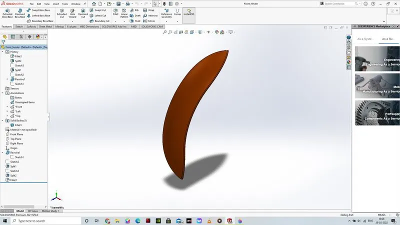
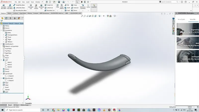
Part Images:
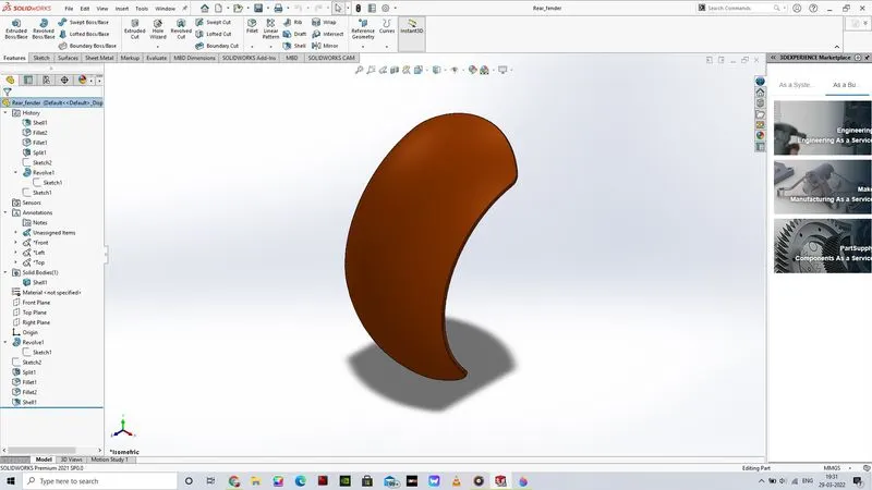
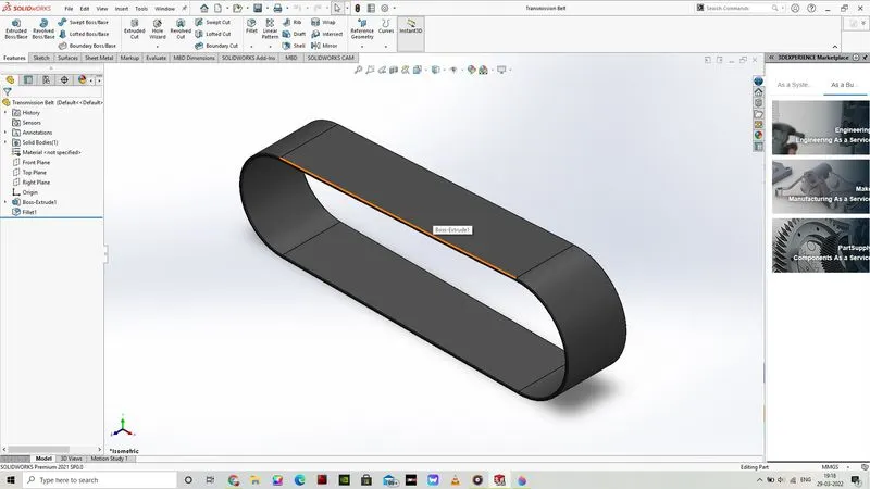
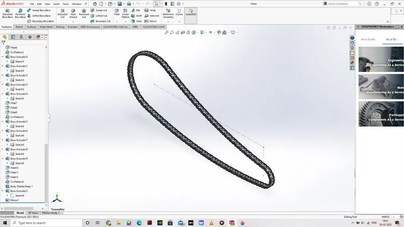
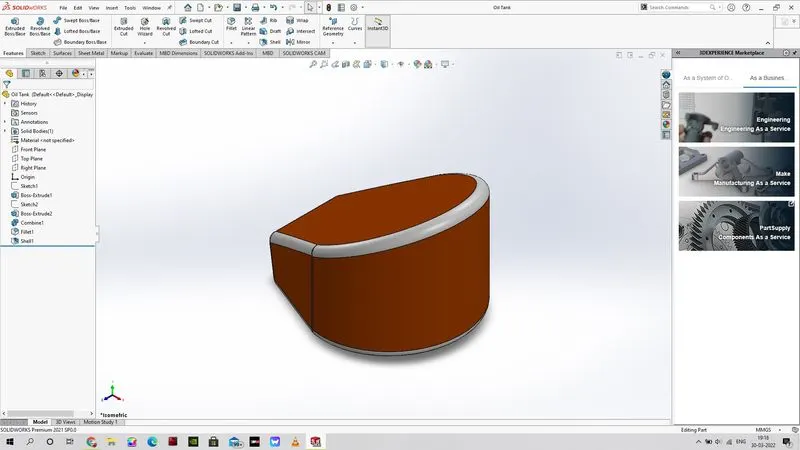
Assembly Image:
Render Images:
Conclusion:
The process that has been used for the creating, modelling, assembling and rendering of the model of american chopper bike has been completed and is created and modelled by using the dimensions and units mentioned in the blueprints information. The creation, assembly and rendering of the chopper bike has impacted and helped me learn various commands of the solidworks 2021 software.
Thank you for the opportunity to learn these information and knowledge, Thank you for your support.