Radar Mast & Final Assembly of Yacht
RADARMAST
open the blue print setup file
insert the superstructure file and allow the surface bodies option
sketch on the mid plane and create plane on basis of sketch
sketch on the plane 1 and extruded upto 140mm
create another plane is offset 20000 from the front plane
sketch on the plane 2 and erevolve around 360 deg and add fillets corectly
create new sketch on the extruded face and extrude upto 324mm
sketch on new makes face and extrud the circle upto 50mm
sketch on new makes face and extrud the circle upto 1800mm
create another plane2 from plane at 250mm distance
sketch on the plnae3 and make another plane on the end of plane 3 sketch
sketch the circle on the plane 4 and sweep upto reference
mirror the rail upto plane2 refference
sketch on the plane 2 and extruded both side of the rails
create sketch on the midplane and create anothe sketch on the plane2
project the curve as refference of above 2 sketches
craeate plane on the top edge of curve and sweep is correctly
sketch on te bottom face and extruded upto 740mm
sketch on the new body and extrude to 200mm
appli chamfer on the top edges and add filleds on all sides
sketch on the midplane and extruded upto rail
create sketch on the top face of bocx and extruded 180mm
new sktch on the midplane and extrudde upto rail
sketch on the new make body and revolve around 180deg
apply fillets properlly
mirror the l shape body and revolve part in the opposite direction rail
sketch on the bottom face of model and extrudedd upto the radarmast surface
create a new o plane from the 270mm distance of midplane
sketch on the plane 5 and revolve around 360dwg
dome feature apply on the back side of revolved part
mirror all body in to refference of midplane
sketch on the bottom plane and extrude upto last maked revolve body
create new plane from offset of mid plane
mirror the revolve part upto refference of plane 7
change the appearence of body to 255,255,255
change appearence of aantenas and bottom of radars to 100,100,100
change the appearence of rail into 192,192,192
save the fiele as radarmast
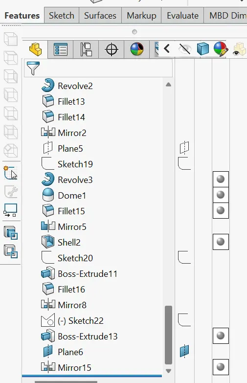
features tree of radarmast:
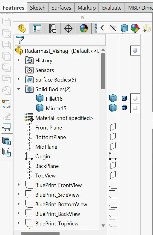
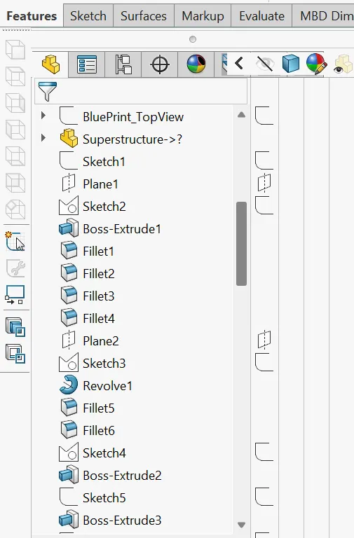
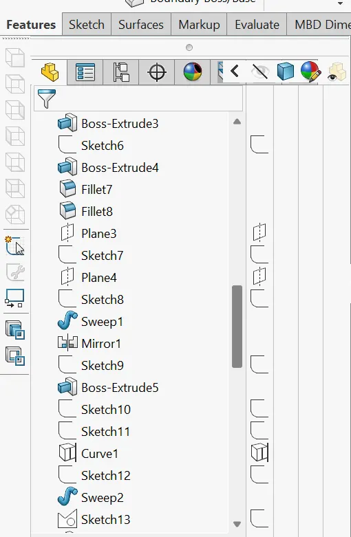
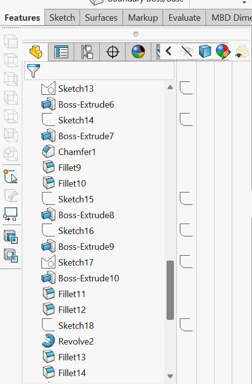
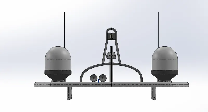
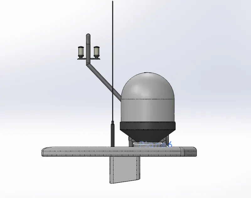
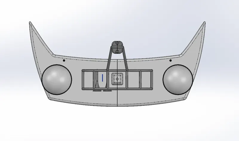
views of radarmast:
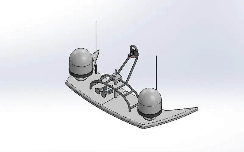
google drive link of radarmast:
https://drive.google.com/file/d/1qbZKNs7Dut9Z1z3H-ykHz1ul3WuDnXFG/view?usp=sharing
ASSEMBLY
open thwe assembly module in the sollid works
insert the hull component into assembly mode and its fix automatically
insert supersctructure component and its automaticaly fix in the hull
insert fornt seat component and its automaticaly fix in the hull
insert radarmast component and its automaticaly fix in the superstructure
insert middle seat component and its automaticaly fix in the hull
insert rear seat component and click on outside of hull
bottom face of rear seat and top face of hull can be coincidented
midplanes of hull and rear seat become coincidented
give a 50mm distance of rear seat upto back end portion of hull
insert garage door component and click on outside of hull
coincident the midplane of hull and midplane of door
side hole of door and screw of hull become concentric
insert the propeller component
inside of propeller and and out side of back shaft of hull become concetric
back face of propeller and front face of shaft become coincident
repeate the process for remaing shafts
insert radar component and click on the outside of hull
cylindrical portion of radar and shatf of radarmast become concentric
outer face of radar and top face of shaft of radarmast become coincident
features tree of assembling:
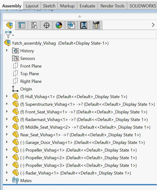
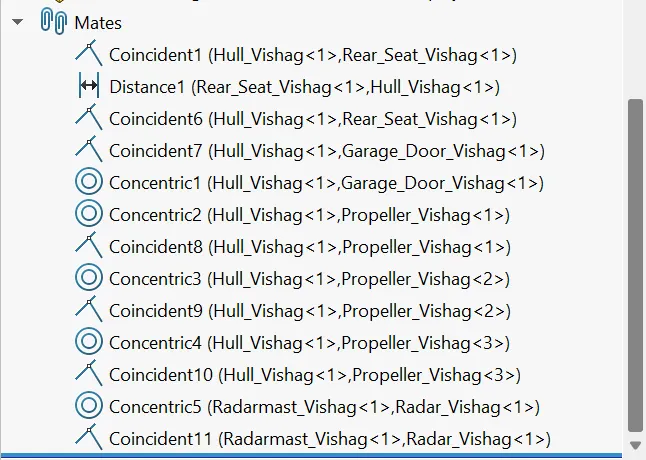
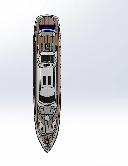
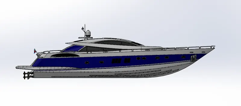
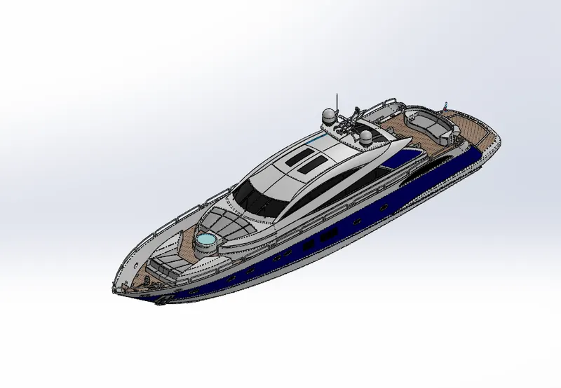
views of assembling:
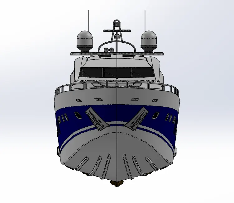
google drive link of assembling:
https://drive.google.com/file/d/1DIpploD-87ddD6zZF54u0ssyhAx-wlUZ/view?usp=sharing
RENDERING
add an background in the scene such as downloaded images
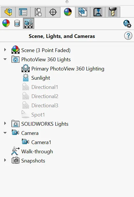
open the render tool in photoview 360
set the camera set up properly as needed direction
open the edit scene and add a background image from the browser
add an enviroment image for looking very orginal
change the plane align upto xy and offset is set in to zero
set the back bround brightness and rendering brightness an needed values
add the display state correctly
open the options tool and set the size of image
make quality of renders quality as need pixel
add custom render and bloom and direcct caustics as needed numbers
open the preview window to check the as shown the getting final image
add sunlight or direction light properly to the climate
and add addition light of spot light and point light
check the image ones more to look in naturally
open the final render , its take more time for rendering process
zoom option used to set rendering size
use advanced image processing to color of the body and enviroment
savr the final render umage inthe as needed folder
compire option used to check the difference of 2 images properlly
open the shcedule render to check the all maked changes and save theis in a correct folder
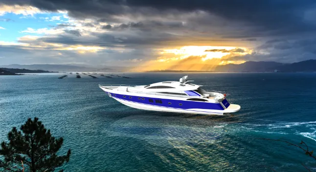
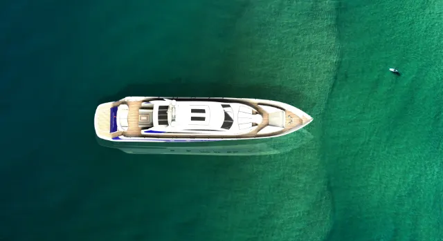
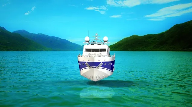
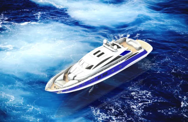
the same processs are uses in the front , top , side , isometric and camera images
rendered images:
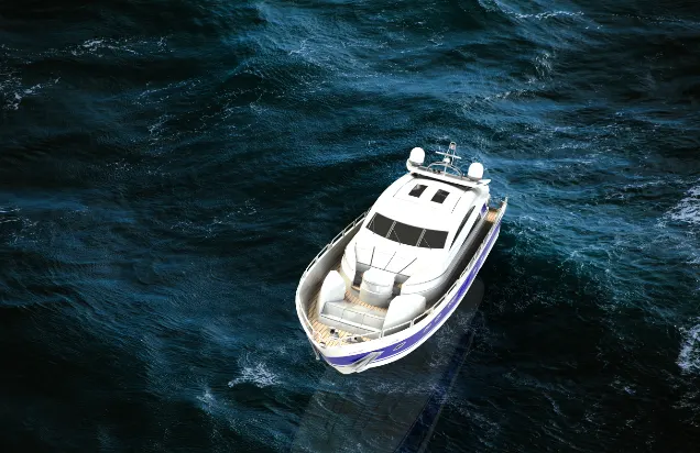
google drive link of rendering:
https://drive.google.com/file/d/1DIpploD-87ddD6zZF54u0ssyhAx-wlUZ/view?usp=sharing
conclusion:
all parts of yatch are modledd successfully using solid works modeling environment
all parts inserted in to assembly ans yatch assembled successfully
photorealistic image ofare makes successfully