Radar Mast & Final Assembly of Yacht
American Predator Yacht
Objective:
- The objective of this project is used to create a model of different parts of the yacht using Solidworks.
- To assemble the different parts modeled for the yacht.
- To create a photorealistic model of the yacht and Render the model using Solidworks photoview 360 or solidworks visualize.
Part modeling:
- Part modeling you can create a part from a conceptual sketch through solid feature-based modeling, as well as build and modify parts through direct and intuitive graphical manipulation.
Parts to be modeled for Yacht:
The following parts of the Yacht are modeled in solidworks and assembled together.
- Hull
- Superstructure
- Propeller
- Garage door
- Radar
- Radarmast
- Front seat
- Middle seat
- Rear seat
Types Of Commands and Its Explanation:
Sketch – Create the sketches and decide how to dimension and where to apply relations.
Features – Select the appropriate features, such as extrudes and fillets, determine the best features to apply, and in what order to apply those features must be decided.
Surfaces – Surfaces are a type of geometry that can be used to create solid features.
Assembly – Select the components to mate and the types of mates to apply.
Sketch:
Creating a model usually begins with a sketch. From the sketch, we can create features. We can combine one or more features to make a part. Then, we can combine and mate the appropriate parts to create an assembly. From the parts or assemblies, we can then create drawings.
3-D Sketch:
When sketching in 3D, we can snap to the major directions, X, Y, or Z, and constraints are applied along X, Y, Z respectively. These are constraints to the global coordinate system.
When sketching on a plane, we can snap to the horizontal or vertical directions in the plane, and constraints are applied to the horizontal and the vertical. These are constraints to a plane, planar face, etc.
Sketch Commands:
Smart Dimension – Creates a dimension for a selected sketch entity.
Line – Line is one of the first sketching tools in Solidworks Sketch Command Manager which can be drawn horizontally, vertically or at any angle. It plays very important role to complete the 2D drawing of the product or part and very easy to utilize its features.
Circle – The circle is another important sketching tool which enables to create the circular drawing on the graphics area. There are two circle tools are available and they are “Center Circle” and “Perimeter Circle”.
Rectangle – Sketches rectangles or square with a center point at a selected angle. Parallelogram sketches a standard parallelogram.
Spline – A two or three dimensional curve defined by a set of control points. Points within a spline can be added or deleted.
Sketch Fillet – A tangent arc in between two sketch entities can be created.
Point – Inserts a point or vertex into a sketch entity. This cannot be deleted if it is part of sketch endpoint or center point.
Text – It can be used to write the next necessary wherever required either it’s a plane or face.
Offset Entities – Copy a sketch entity to a specified distance from the original, entity. Must have a sketch entity already drawn and selected use this tool.
Sketch Picture – Insert an image file into the background of a sketch. This allows the user to 2D sketches based off of the image. Use the sketch picture property manager to alter the inserted image.
Convert Entities – Convert entities enables you to copy model edges into your active sketch. These sketch elements are automatically fully defined and constraints with an On Edge relation. Convert Entities like Offsets Entities except that the offset distance is always zero.
Features:
Some sketch-based features are shapes such as bosses, cuts, and holes. Other sketch-based features such as lofts and sweeps use a profile along a path. Another type of feature is called an applied feature, which does not require a sketch. Applied features include fillets, chamfers, or shells. They are called “applied” because they are applied to existing geometry using dimensions and other characteristics to create the feature. Typically, we create parts by including sketch-based features such as bosses and holes. Then we add applied features. It is possible to create a part without sketch-based features.
Feature Commands:
Extruded Boss/Base – One of the oldest commands in the SOLIDSWORKS software is the boss/base extrude command. An Extruded Boss/Base feature will allow us to take 2D sketch and add thickness to it in the third dimension.
Extruded Cut – It’s a tool to remove material by projecting a sketched section normal to the sketching plane.
Split – Lines are used to divide model faces into two. Split lines are created like any other sketched feature. They can be one or more connected sketch entities. They must be oriented so that they will pass through model faces when projected normal to the sketch plane.
Dome – It can add one or more domes to the selected planar or non-planar faces. The software calculates the distance using the radius of the arc as a basis for the dome.
Pierce Relationships – The pierce relationship is used in sweeps. It can be thought of as a 3D Coincident relationship. In our spring, the circle will follow the helix. Think of the helix as a thin piece of wire and the profile sketch as being drawn on a piece of paper. If we stick the wire through the paper at the center of the circle, this would be a pierce relationship. When we perform the sweep, the paper will slide along the wire, held at the pierce point.
Project Curve – Select Bi-directional to create a projection that extends on both sides of the sketch. The curve can be used as a path for a sweep.
Composite Curve – We can create composite curves by combining curves, sketch geometry, and model edges into a single curve. Composite curve can be used as a guide curve when creating a loft or a sweep.
Wire Frame – Wireframe is a view mode in which all edges of the part or assembly are displayed.
Vertex – A vertex is a point at which two or more lines or edges intersect. Vertices can be selected for sketching, dimensioning, and many other operations.
Materials – Materials are applied to parts to define the engineering properties. These properties include such properties as density and yield strength.
Part Modeling Description:
Blueprint:
A blueprint is a reproductive of a technical drawing or engineering drawing using a contact print process on light-sensitive sheets.
A blueprint is a guide for making something, it’s a design or pattern that can be followed. They were easier to read and faster to make.
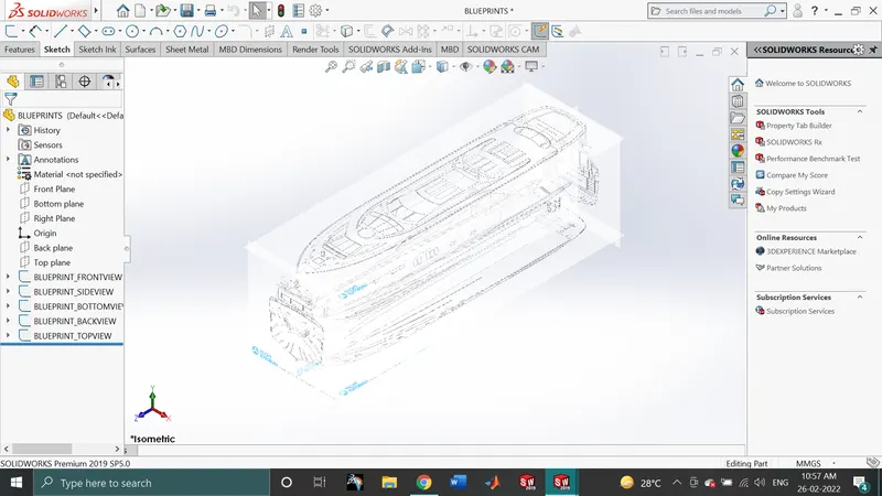
The above shown blueprint was used to model the yacht in a fully defined constraint. For setting up the blueprint the sketch pictures options were used and place the different blueprints at the required planes.
1.Hull
A hull is the watertight body of a ship or boat. The hull may open at the top (such as a dinghy), or it may be fully or partially covered with a deck. The line where the hulls meets the water surface is called the waterline.
The hull of a ship is the most notable structural entity of the ship. To define the hull, it can be said that its is the watertight enclosure of the ship, which protects the cargo, machinery and accommodation spaces of the ship from the weather, flooding, and structural damage.
- The hull is a watertight body of a vessel which may be open or may be partially covered with a deck.
- Hull has several watertight decks and bulkheads as the major transverse membrane.
- Depending on the structural arrangements, there may be longitudinal members for strengthening purpose.
- The intermediate member of the hull consists of girders, webs and stringers.
In our model the hull was designed along with the following parts of the yacht,
Aft – Referring to the aft means in or toward the back of the yacht.
Anchor – the anchor is a heavy object that drops down into the water to keep a boat or yacht from moving.
Beam – The beam is the widest point of a boat or yacht.
Berth – The sleeping area of a yacht is the berth.
Bow – The front of the yacht’s hull is the bow.
Bridge – All of the controls of the yacht are located on the bridge, which is also sometimes called the cockpit.
Cabin – Private rooms and living compartments in a yacht are called cabins.
Cleat – The cleats are the metal or plastics fitting on boats where sailors attach lines.
Deck – The part of the yacht where we can walk around outside is called the deck.
Draft – The draft is the minimum depth of water needed for a boat to float.
Galley- Sailors call the kitchen of a boat the galley.
Gunwale – The gunwale is the upper edge of the side of a boat or yacht.
Hatch – The hatch is the opening that connects the deck of a boat with the cabin’s underneath. Some yachts have several hatches.
Helm – The steering mechanism of a yacht is the helm.
Keel – The keel is the part of the hull that runs down the middle from the bow to the stern. The keel is considered the foundation or backbone of a boat.
Knots – Knots describe the speed of a boat in nautical miles per hour. A single mile is the same as a little more than 1.15 regular miles, meaning that a boat travelling at 25 knots is going almost 29 miles per hour.
Line – Rope used on a boat or yacht is called line. Sailors need to know how to tie proper knots in the lines to keep boats secure when they are docked.
Port – If we are standing or sitting on a yacht looking toward the front of the vessel, the port side is the left side.
Porthole – Windows in a yacht or boat are called portholes.
Rig – The rig includes the sails and any devices needed to control the sails. Rigging includes equipment such as the mast, boom, yards, and spreaders.
Starboard – When we are standing or sitting on yacht looking toward the front of the vessel, the right side is the starboard side.
Stern – The back of the yacht’s hull is the stern.
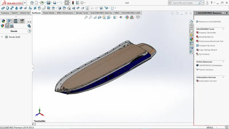
Commands used to model:
In sketch:
- Line
- Spline
- Circle
- Rectangle
- Arc
- Slot
- 3-D sketch
- Sketch picture
In Surfaces:
- Extruded surface
- Revolved surface
- Lofted surface
- Surface trim
- Surface fill
- Surface knit
- Delete face
In features:
- Project curve
- Chamfer
- Fillets
- Reference plane
- Split
- Split line
- Extruded BossBase
- Extruded cut
- Mirror
Modelling Procedure:
- The first step for modelling the yacht was creating a blueprint of it.
- Then the blueprint was placed at the required planes, by using it first the hull was designed.
- To get the shape of the hull the projected curve was produced by drawing the required sketch using splines with the help of blueprint.
- Then the curves were lofted to create a lofted surface and the remaining unwanted surface was trimmed using surface trim.
- Then the back portion of the hull were the propeller needs to be placed was extruded using extruded surface and all the surface created must be knitted together to remove the gaps between the surfaces.
- Then the offset option was used and another surface was created and both surface was filled using surface fill to create the outer shell of the hull which will be converted into a solid body at last.
- Shell feature was used to create the front portion of the hull where the deck surface meets.
- Then the deck surface was created using extruded boss/base and extruded cut.
- Then the required chamfers and fillets were created wherever necessary.
- All the windows and portholes were created using extruded cut and fillets were add around the edges.
- For creating the smooth edges around the berth window the reference plane were created and a circle for required dimension were make pierced and then swept around the edges of the windows.
- The rails at the bottom of the yacht were created using extruded boss/base and the chamfers were applied both the sides.
- The cable rollers were created using extruded boss/base and swept and the head part of it was created using revolved boss/base and extruded cut was used to cut through the extruded and Dome was created over it.
- Helix/spiral sketch was created to sweep the rope around the cable rollers.
- By using slot option the Rope hangers were extruded and the dome was applied and then the linear pattern was used to create one more.
- The window bars were created using extruded boss/base.
- The staircase was created by using extruded boss/base and the hand support bar was created swept boss/base.
- The railings around the hull was generated with the help of blueprint and the projected curve was produced and the railing reference was swept using swept boss/base.
- The axles for the propeller and the surfer were created using revolved boss/ base option and using the 3d sketch.
- The anchors were created by sketching the first half and extruded using extruded boss/base and the other half was mirrored.
- Finally, the garage portion was created by using extruded cut and the portion was saved for later use by using split option.
- By using the split line option, the painting portion for our hull was split separately.
- Then the other half of the Hull and the Alex of the surfer and propeller was mirrored to form the complete hull using Mirror tool.
- Now the part was saved by adding proper appearances and fillets.
2.Super Structure:
A super structure is an upward extension of an existing structure above a baseline called ground level and it usually serves the purpose of the structure’s intended use. A super structure is a decked structure on the freeboard deck, extending from side of the ship.
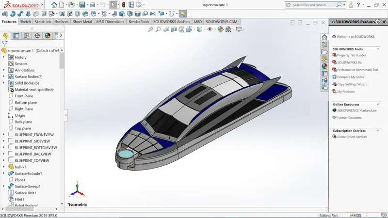
Commands used to model:
In sketch:
- Line
- Spline
- Circle
- Rectangle
- 3-D sketch
- Sketch picture
- Center points arc
In Surfaces:
- Extruded surface
- Revolved surface
- Lofted surface
- Swept surface
- Ruled surface
- Knit surface
- Trim surface
- Extend surface
- Fillets
- chamfer
In features:
- Project curve
- Reference curve
- Split
- Split line
- Convert entities
Modelling Procedure:
- The deck surface from the hull was imported and the super structure was modelled over it.
- The side surface of the super structure was created by using extruded surface, lofted surface, filled surface, trim surface and knit surface.
- The front side of the super structure was designed to have four rest beds which were created using extruded boss/base, Fillets and dome.
- The front edges of the super structure were provided with a water feature which was created using extruded boss/base, extruded cut, filled with a water appearance.
- The windshield was created by extruded cut and the wipers were created by using 3d sketch and reference plane with the help of swept boss/base.
- The portholes for the superstructure were created by using extruded surface, trim surface and extend surface.
- Ruled surface was used to fill the left-out edges.
- The back doors of the super structure were created using extruded cut, fillets and reference plane.
- Then all the surface generated were knitted together to form a solid body.
- The super structure consists of two surface bodies and five solid bodies.
- The other half was mirrored and the proper fillets and appearance was added and finally the part was saved.
3.Propeller:
There can be one, two or three propellers. It is a most important part of the ship without which a ship can’t move. So, the main function of propeller is to propel the ship in the forward direction by producing thrust on water. Its working principles are Newton’s third law of motion and Bernoulli’s theorem.
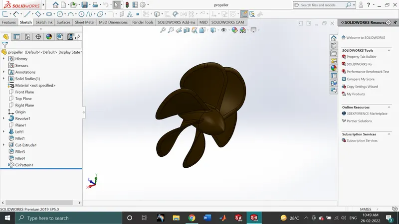
Commands used to model:
In sketch:
- Line
- Spline
- Circle
In features:
- Extruded cut
- Revolved boss/base
- Lofted boss/base
- Reference plane
- Fillets
- Circular pattern
Modelling Procedure:
- The center portion of the propeller was sketched and revolved using revolved boss/base.
- Then the blades were created using the reference plane, lofted boss/base and fillets.
- Then the remaining five blades were created by using circular pattern.
- Then the center circular portion was removed using extruded cut option.
- Finally, the part was saved by adding the proper appearance.
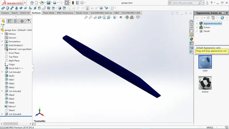
4.Garage Door:
A garage door is a large door on a garage that opens either manually or by an electric motor. Garage doors are frequently large enough to a accommodate automobiles and other vehicles. The operating mechanism is spring-loaded or counterbalanced to offset the weight of the door and reduce human or motor effort required to operate the door. Less commonly, some garage doors slide or swing horizontally. Doors are made of wood, metal, or fiberglass, and may be insulated to prevent heat loss.
Commands used to model:
In sketch:
- Line
- Spline
- Circle
- Text
In features:
- Extruded cut
- Reference plane
- Fillets
- Shell
- Mirror
Modelling procedure:
- The solid body split while creating the hull was imported to model the garage door.
- By using the extruded cut the chamfered face for the door was created.
- Then by using the shell feature the solid body for our garage door was created and proper fillets were applied.
- Then the door holders on both sides were created using extruded cut.
- Then the second half of the garage door was created using mirror tool after the required fillets.
- Then the text over the garage door “ ” was created using the text option in sketch feature.
- Finally, the part was saved by applying proper appearance.
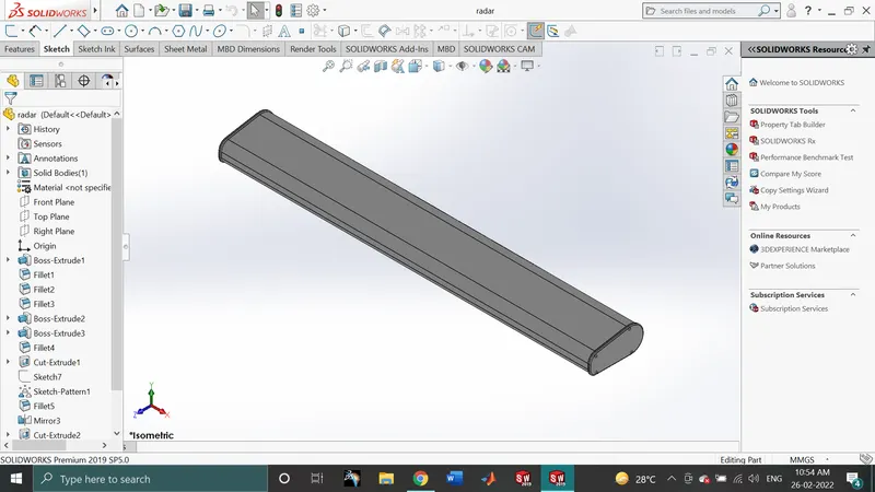
5.RADAR:
Marine RADARS are X band or S band RADARS on ships, used to detect other ship and land obstacles, to provide bearing and distance for collision avoidance and navigation at sea. They are electronic navigation instruments that use a rotating antenna to sweep a narrow beam of microwaves around the water surface surrounding the ship to the horizon, detecting targets by microwaves reflected from them, generating a picture of the ship’s surrounding on a display screen.
Commands used to model:
In sketch:
- Line
- point
- Circle
- Text
In features:
- Extruded cut
- Extruded boss/base
- Sketch pattern
- Fillets
- Split line
- Mirror
Modelling Procedure:
- By drawing the required sketch, the body of the Radar was created using extruded boss/base.
- By using the sketch pattern, the four dotted holes were created using extruded boss/base and extruded cut.
- The radar has a circular slot underneath which was created using the extruded cut.
- The other half was mirrored with the help of mirror tool.
- The text over the Radar was creating using the text option in sketch and then split line was used to generate over the face of the Radar.
- At last the Radar must be filleted around the edges of the body and also around the four holes.
- Finally, the part was saved by adding proper appearance.
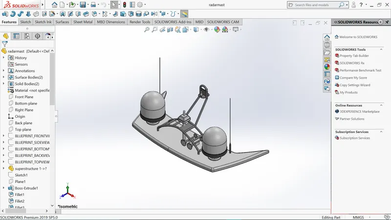
6.RADARMAST:
A mast is a vertical ship structure mounted on top of bridge and forward of the forecastle towards the ship’s bow. It accounts for the support platform for the ships derrick and hold necessary equipment’s such as RADAR, navigation light and ship horn in case of foremast. They are made of high tensile steel with added rigidity based on the size of derricks it holds. Other than a ships main mast is also used to hoist ships flags.
Out of different parts of ship the main job of mast is to hold necessary equipment such as RADAR receiver, navigation lights, ships, horn, flags and derricks in some case.
Commands used to model:
In sketch:
- Line
- Spline
- Rectangle
- Arcs
- Sketch pictures
In features:
- Revolved boss/base
- Lofted boss/base
- Extruded boss/base
- Reference plane
- Fillets
- Swept boss/base
- Mirror
- Shell
- Dome
Modelling Procedure:
- The first half of the radar was modelled with the help of blueprint and then the other half was mirrored with the help of mirror tool.
- The body of the radar was created using extruded boss/base and revolved boss/base.
- The antenna for the radar was also created using the extruded boss/base.
- The lamp stand along with the connecting rod were created using the swept boss/base and mirror tool.
- The horn was created by using the revolved boss/base, dome and shell.
- Then the fillets and chamfers were applied wherever necessary.
- Finally, the part was saved by applying appropriate appearances.
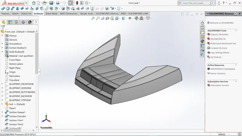
7.Front Seat:
Front seats feature two connected seats that are built back-to-back from one and other. They have a built-in storage unit underneath them. Lounge seats can also fully recline right back to make it easier for you to kick your feet up and get more comfortable.
Commands used to model:
In sketch:
- Line
- Spline
- Circle
- Sketch picture
- Arcs
In Surfaces:
- Extruded surface
- Revolved surface
- Lofted surface
- Swept surface
- Ruled surface
- Knit surface
- Trim surface
- Extend surface
In features:
- Extruded cut
- Revolved boss/base
- Chamfer
- Fillet
- Mirror
- Dome
Modelling Procedure:
- The front seat of the yacht was also created with the help of blueprint.
- The first half was modelled and other half was mirrored using mirror tool.
- The front seat was placed before the super structure facing the water feature of the superstructure and the back end must be placed on the bow of the yacht.
- The body of the front seat was modelled using swept surface, extruded surface, filled surface, lofted surface and the unwanted part was removing using the trim surface.
- Then the four rest beds were created using the extruded boss/base and the dome was created over the face of the beds separately.
- Then the required fillets and chamfers were created with extruded thin surface.
- Finally, the part was saved by adding proper appearances.
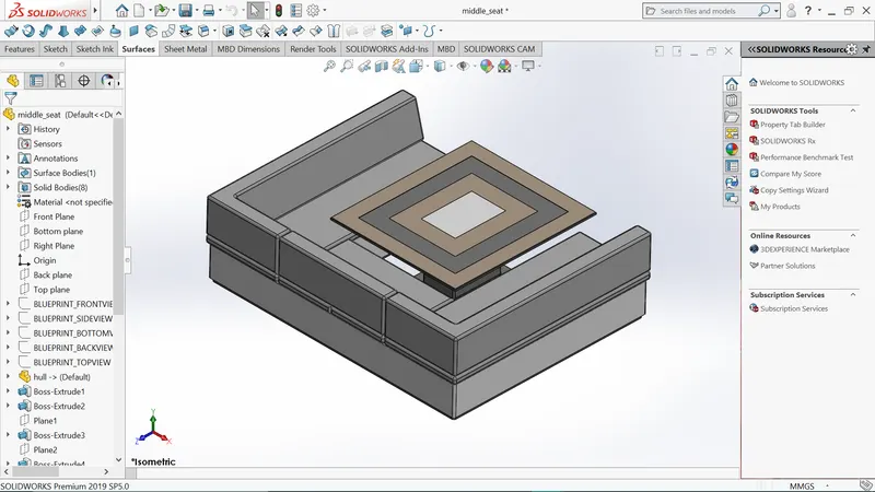
8.Middle Seat:
The middle seat in our model was placed just behind the superstructure. It is provided with a luxury table to dine out. It can also be used to have casual meetings with co-passengers.
Commands used to model:
In sketch:
- Line
- Rectangle
- Sketch pictures
In features:
- chamfer
- Extruded boss/base
- Reference plane
- Fillets
- Mirror
- Shell
Modelling Procedure:
- The middle seat was created using the extruded boss/base and by applying the chamfers and fillets as required.
- All the surfaces created must be knitted together by using the knit surface option.
- The dinning table was also created using reference plane, extruded boss/base, offset, chamfers and mirrors.
- Then the second half of the middle seat must be mirrored symmetrically.
- Finally the part was saved by approving the proper appearances.
9.Rear Seat:
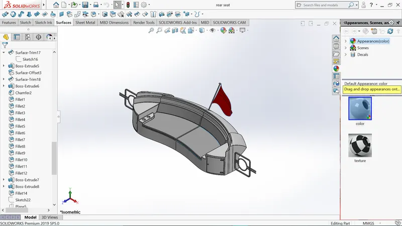
The rear seat was placed at the end of the deck surface. The rear seat consists of lockers racks, steel doors for our stairs. The flag was also placed behind the rear seat since it’s the end part of our yacht. To have a nice view from the yacht while having a drink the rear seat was also provided with a slot to rest the glass or mug.
Commands used to model:
In sketch:
- Line
- Spline
- Circle
- Sketch picture
- Arcs
- Rectangle
In Surfaces:
- Extruded surface
- Revolved surface
- Lofted surface
- Swept surface
- Ruled surface
- Knit surface
- Off set surface
- Filled surface
In features:
- Extruded boss/base
- Revolved boss/base
- Reference plane
- Fillet
- Mirror
Modelling Procedure:
- The main body of the rear seat was modelled using swept surface, off-set surface and the remaining portion was trimmed using trim surface tool.
- By using the reference plane the seats were created with the help lofted surface, surface trim and extended surface.
- The flag post was created using revolved boss/base and the flag was created by drawing the required 3D sketch and then 3D sketches were lofted to form the flag.
- The tail lamps were created by using extruded boss/base, fillets and mirror tool.
- The steel gates for stairs were designed by using the reference plane and swept surface.
- To remove the gaps the all surfaces must be knitted together using knit surface.
- The required fillets and chamfer were created before mirroring the second half using mirror tool and after mirroring the uncreated areas were filleted again.
- Finally the part was saved by adding appropriate appearances.
Assembly
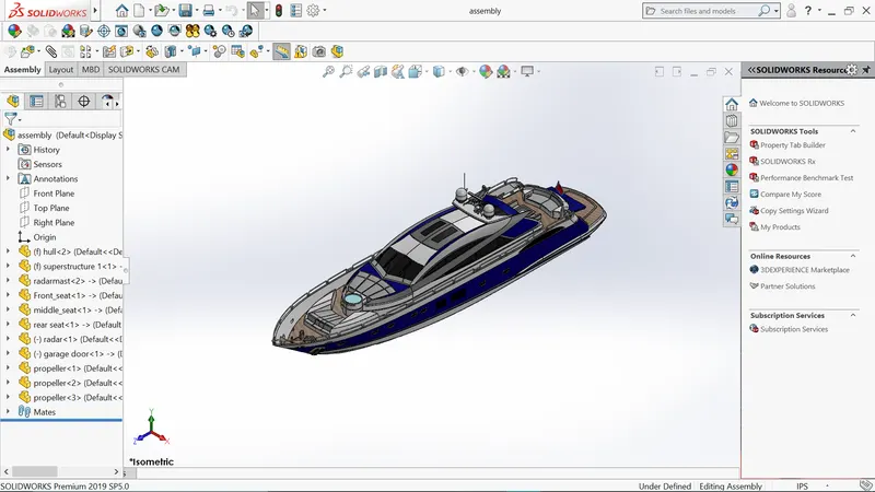
An assembly is a document In which parts, features, and other assemblies (sub-assemblies) are mated together. The parts and subassemblies exist in documents separate from the assembly. For example, a piston can be mated to other parts, such as a connecting rod or cylinder. This new assembly can then be used as a sub-assembly in an assembly of an engine. The extension for a solidworks assembly file name is SLDASM.
Assembly Commands
- Smart mate – A smart mate is an assembly mating relation that is created automatically.
- Mate – A mate is a geometric relationship, such as coincident, perpendicular, tangent, and so on, between parts in an assembly.
- Mate group – A mate group is a collection of mates that are solved together. The order in which the mates appear within the mate group does not matter.
- Sub-Assembly – A sub-assembly is an assembly document that is part of a larger assembly.
- Insert Components – We can insert multiple instances of the group of components without closing the property manager.
Assembly Procedure:
Import all the parts manually by using insert components option.
Then fix the hull part by applying the coincident made to the top. Right and front planes of the assembly and hull respectively.
Then for each part apply the necessary mates required by the blueprint using coincides mates, angle mates, distance mates, etc.
Advanced mate was also used wherever required.
Rendering:
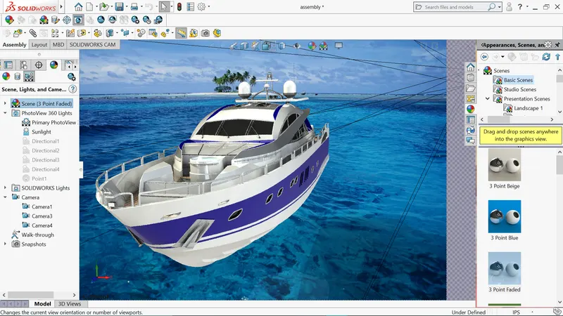
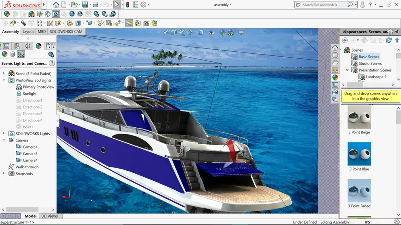
Rendering of the solidworks model is done using PhotoView 360 and Solidworks Visualize.
PhotoView 360 is a visualization and rendering solution included with SolidWorks. Providing a highly interactive environment for viewing designs as well as for creating photo-realistic renderings it can be used to showcase our designs.
SolidWorks Visualize (formerly known as Bunkspeed) provides a suite of standalone software tools that combine industry-leading rendering capabilities with visual design-oriented features and workflows, allowing easy and fast creation of visual content that communicates a design’s vision, passion, and emotion.
PhotoView 360:
PhotoView 360 is a software package, separate to SolidWorks, which generates digital lifelike images (photorealistic image) from SolidWorks files. PhotoView 360 is an easy and quick way to produce high quality photorealistic images.
- Environments – Environments can be looked upon as backdrops and can be applied in a similar manner as the appearances are applied to faces or parts.
- Appearances – There are a wider range of appearance in PhotoView 360 than in SolidWorks. If we wish to change an appearance just drag and drop the chosen appearance into the part and it will replace the existing one.
- Lighting – Lights may be added in the same way a photographer adds lights when taking photographs. PhotoView 360 uses the same lights as SolidWorks but also uses lighting from the rendering environment or scene. photoView 360 has the sophistication to trace light rays and reflections.
- Scenes – Each SolidWorks model is associated with PhotoView 360 scene, for which you can specify properties such as environments and backgrounds. Scenes help to put products in context.
- Decals – Images, such as company logos, can be applied to models.
- Output – The rendered output from PhotoView 360 can be viewed on the screen, or saved to a graphics file.
- Options – PhotoView 360 has its own options. Options allows you to customize the PhotoView 360 settings to reflect your preferences. Options are divided into output image settings, render quality, bloom, contour rendering and direct caustics.
SolidWorks Visualize:
Quickly and easily create professional, photo-quality images, animations, and other interactive 3D content to get your products to market faster.
SolidWorks Visualize allows us to leverage our 3D CAD data to create photo-quality content in the fastest and easiest way we can form images to animations, interactive web content, and immersive virtual reality. It brings our products to life. SolidWorks Visualize is the “camera” for our CAD data.
Conclusion:
Thus the project design, assembly and photo-realistic rendering of an American Predator Yacht was modelled and rendered successfully.