Radar Mast & Final Assembly of Yacht
YATCH ASSEMBLY
1) AIM : To make Yatch assembly
2) OBJECTIVE : Part Modelling of parts, Assembly of modelled parts and Rendering of the Assembly.
3) SOFTWARE USED : Solidworks 2019 and Solidworks Visualise.
4)INTRODUCTION :
Part Modelling :
It refers to create parts in a virtual appearance that are used for final assembly of the product.
Features/Tools for Part Modelling :
Sketch : Used to draw the sketch in 2D view with respect to plane/face. It can be done with respect to 2D or 3D.
Convert Entities : To project the required sketch on the plane or face for current sjetching.
Offset Entities : Offset the sketch to the suitable dimension.
Extrude Boss/Base : Converts 2D sketch into 3D model.
Lofted Base : To add materials between two or more profiles which are closed and spaced.
Revolved Base : To create a 3D model around the axis or referance line.
Extrude Cut : To remove material from the 3D model.
Linear Pattern : To replicate one or more features along one or two linear paths.
Circular Pattern : To replicate the features about the axis.
Fillet : To create rounded internal/external profile on the edges.
Chamfer : To remove the material at the edges of 3D model.
Shell : To remove inner portion of the model leavong a hollow region with suitable wall thickness.
Referance Plane : To create a new plane with suitable options required for sketching.
Spline : To create complex curves by controlling spline points and handles.
Combine : To merge multiple bodies into single body.
Split : To project an entity onto other surfaces which can be used to cut the bodies and also can consume.
Dome : To create dome on 3D model/surface.
Swept Boss : To sweep profile in a required path/direction.
Cut Sweep : To remove material from the model by sweeping closed profile along the closed/open path.
Surface Modelling :
To create a surface of suitable dimension more precisely. It has a vital importance in Aeronautical and Automobile Design.
Surface Features -
Extrude Surface : To convert 2D sketch to 3D surface.
Ruled Surface : To create a surface from the selected edge in a specified manner.
Trim Surface : To remove the connected surface in a suitable shape/direction.
Knit Surface : To combine 2 or more surfaces together. Merge Entities option can be used to make them as a single entity and also control the gap between them.
Surface Sweep : To create a surface by moving the profile along a path specifies path.
Surface Loft : To create complex shaped surface by making transition between multiple profiles and guide curve.
Surface Fill : Used to construct surface to fill a gap in a model.
Surface Extend : To extend a previous surface to the suitable dimension.
DESIGN METHODOLOGY FOR THE YATCH ASSEMBLY :
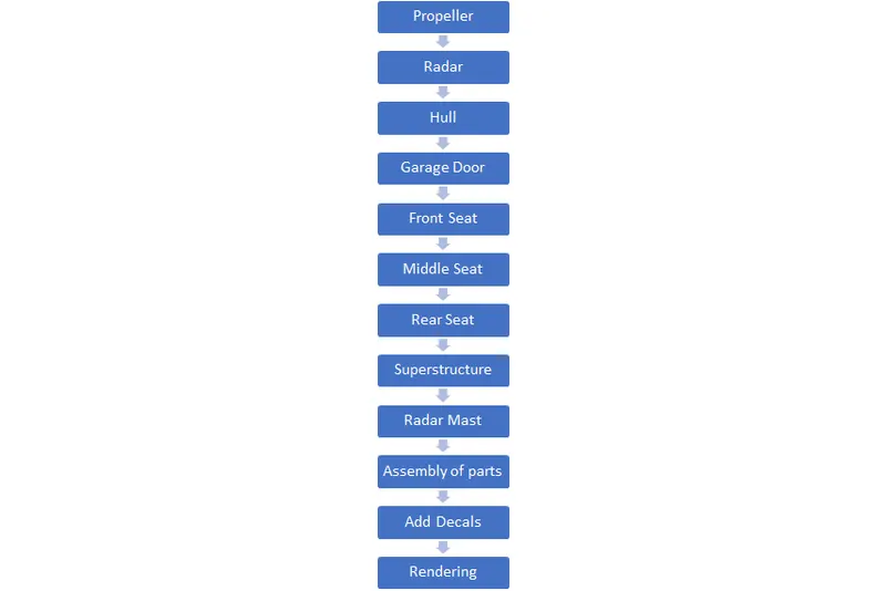
Description of the Modelled Parts :
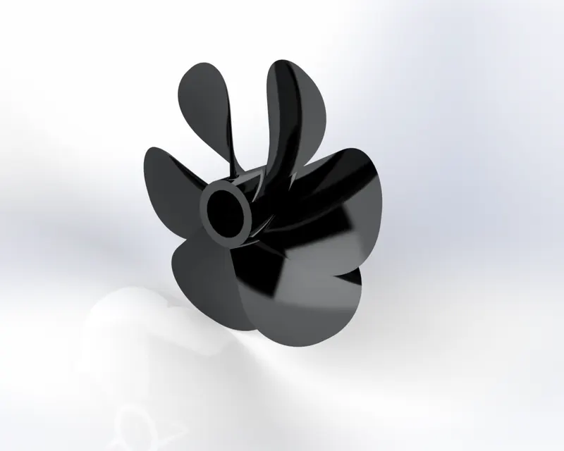
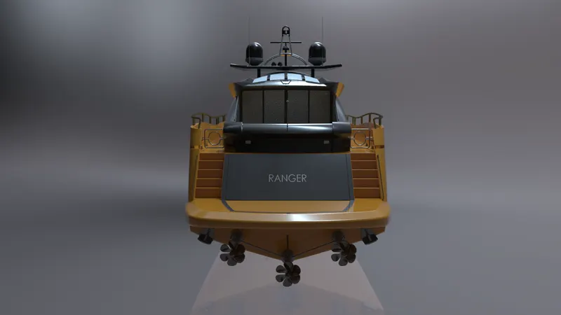
1) Propeller : It is a device with a rotating hub and radiating blades that are set at a pitch to form a helical spiral. It transforms rotational power into linear thrust by acting upon a working fluid.
Features Used :
- Revolve
- Loft
- Fillet
- Extrude Cut
- Circular pattern
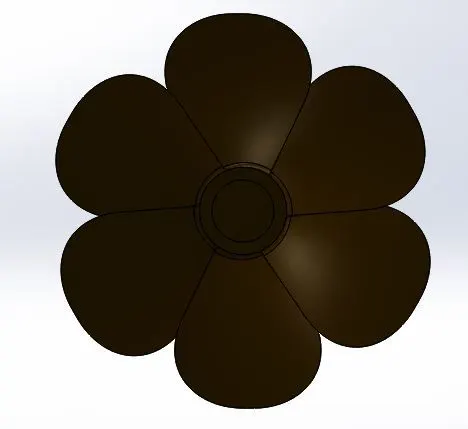
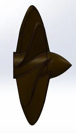
Rendered Image :
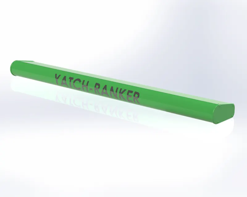
2) Radar : It is a detection system that uses radio waves to determine the range, angle and velocity of objects.
It is mainly used for military purpose.
Features Used :
- Boss Extrude
- Fillet
- Cut Extrude
- Sketch Pattern
- Mirror
- Split Line

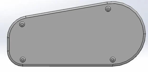
Rendered Image :
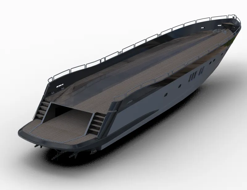
3) Hull : It is a frame or body of a ship. It is the watertight body of a ship or boat. It is also portion of the ship that extends below the water.
Features Used :
- Project Curve
- Surface Loft
- Surface Trim
- Surface Extrude
- Surface Knit
- Surface Fill
- Shell
- Boss Extrude
- Cut Extrude
- Chamfer
- Fillet
- Sweep
- Revolve
- Dome
- Linear Pattern
- Combine
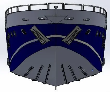
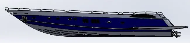
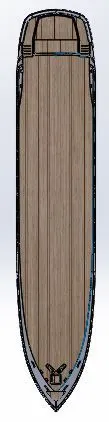
Rendered Image :
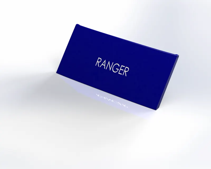
4) Garage Door : It is a garage door inside where vehicles are parked.
Features Used :
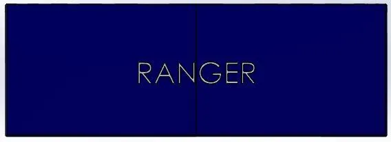
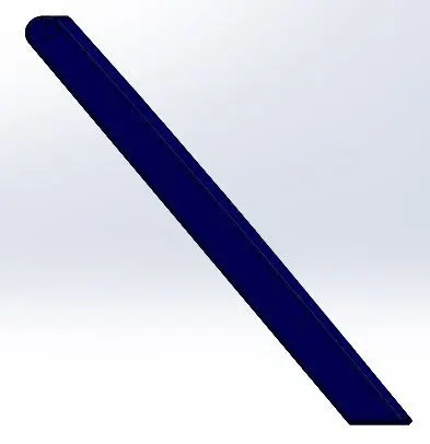
Rendered Image :
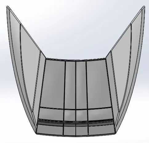
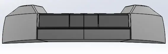
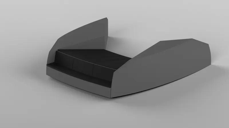
5) Front Seat : An arrangement to sit in the front portion of ship.
Features Used :
- Surface Sweep
- Surface Extrude
- Surface Trim
- Surface Fill
- Surface Loft
- Surface Knit
- Revolve
- Chamfer
- Cut Extrude
- Fillet
- Mirror
- Dome
Rendered Image :
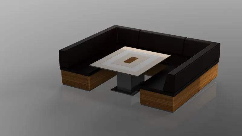
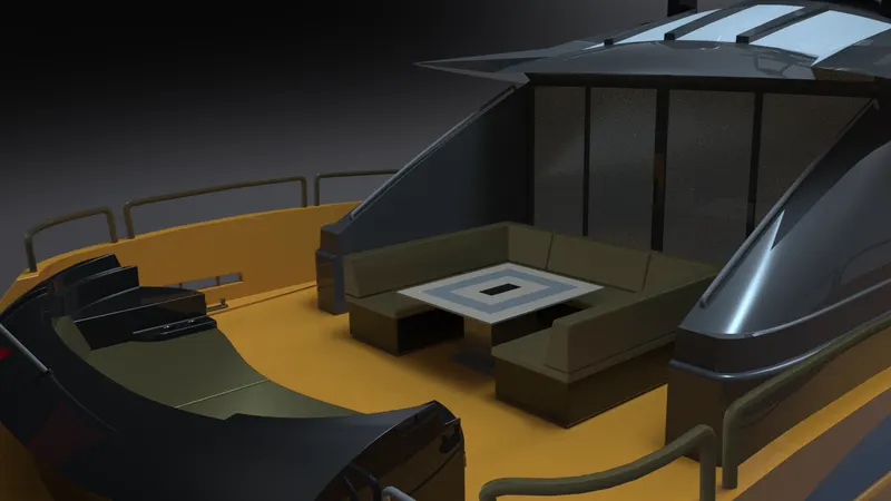
6) Middle Seat : An arrangement to sit in the middle portion of ship.
Features Used :
- Boss Extrude
- Chamfer
- Fillet
- Mirror
- Cut Extrude
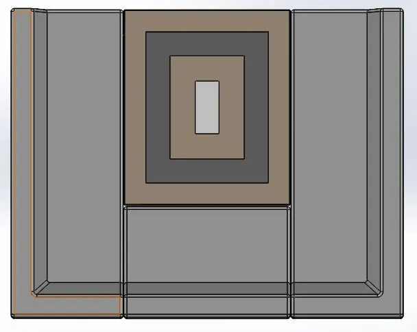
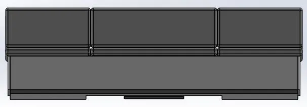
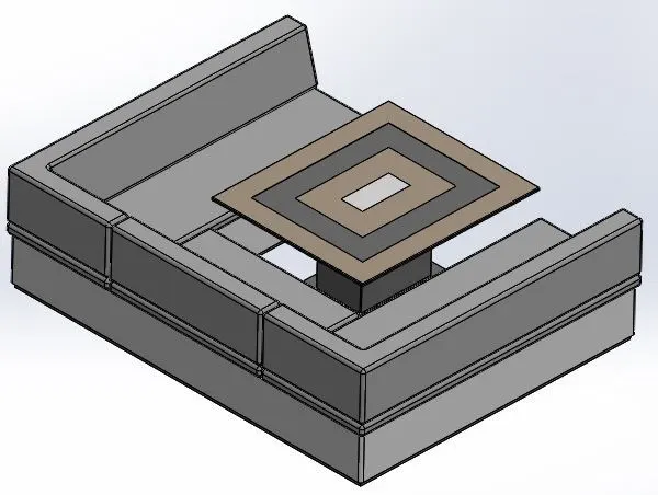
Rendered Image :
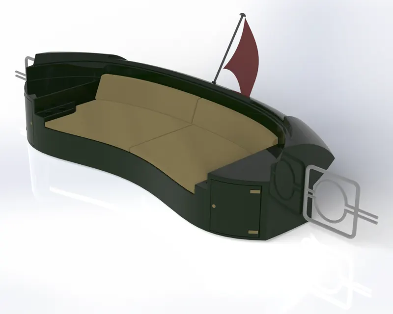
7) Rear Seat : An arrangement to sit in the Rear portion of ship.
Features Used :
- Surface Sweep
- Surface Offset
- Surface Trim
- Ruled Surface
- Surface Knit
- Boss Extrude
- Cut Extrude
- Chamfer
- Fillet
- Sweep
- Mirror
- Revolve
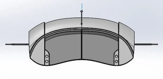
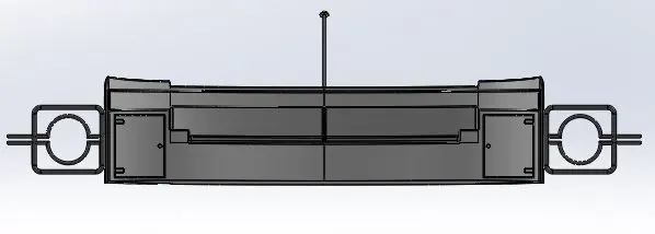
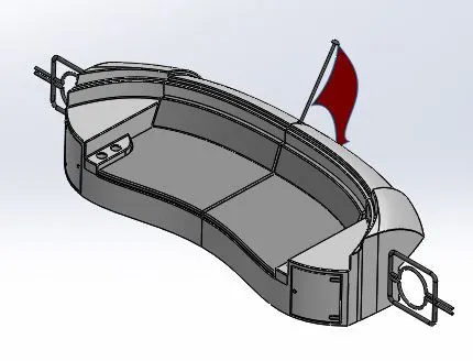
Rendered Image :
8) Superstructure : Part of a ship that is above the main deck.
Features Used :
- Surface Extrude
- Surface Sweep
- Surface Knit
- Fillet
- Ruled Surface
- Surface Trim
- Surface Loft
- Surface Fill
- Surface Extend
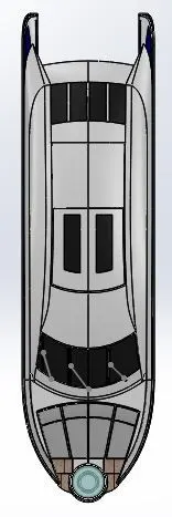
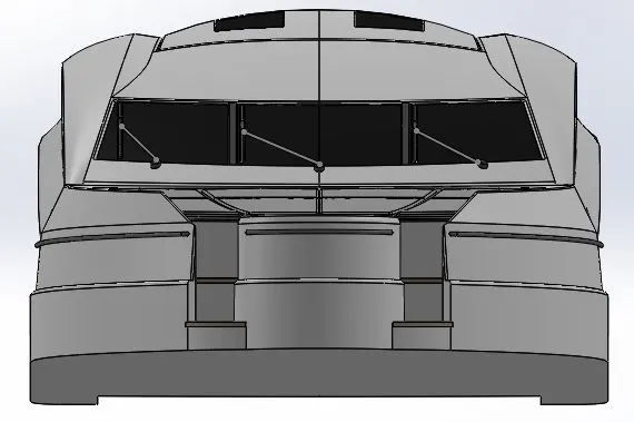
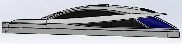
Rendered Image :
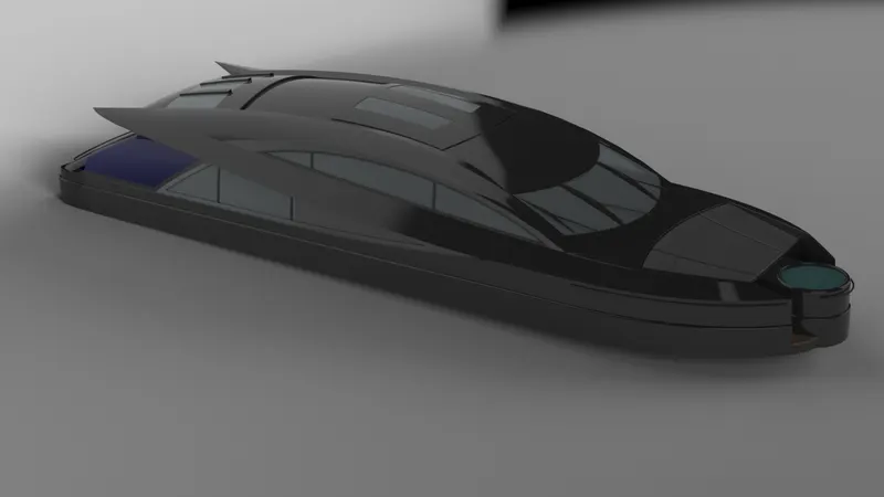
9) Radar Mast :It is an arrangement of spars that is erected vertically on the center line of the ship. It gives necesarry height to navigation light, look out position, signal yard, radar.
Features Used :
- Boss Extrude
- Fillet
- Revolve
- Sweep
- Mirror
- Chamfer
- Dome
- Shell
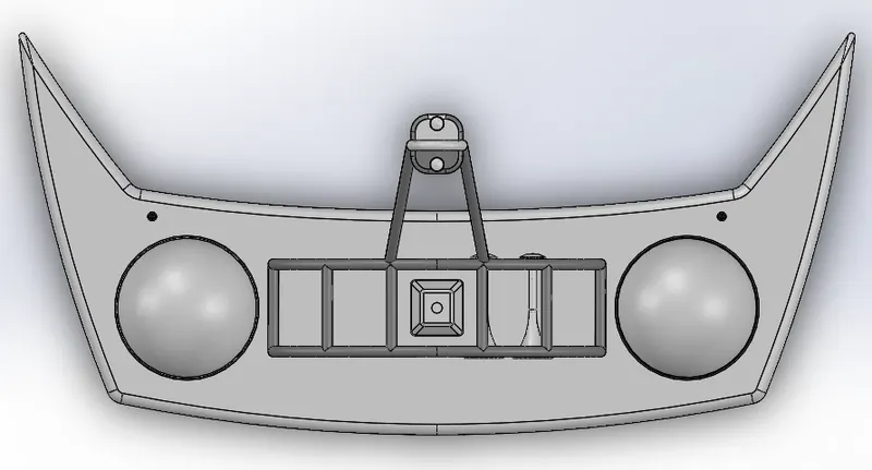
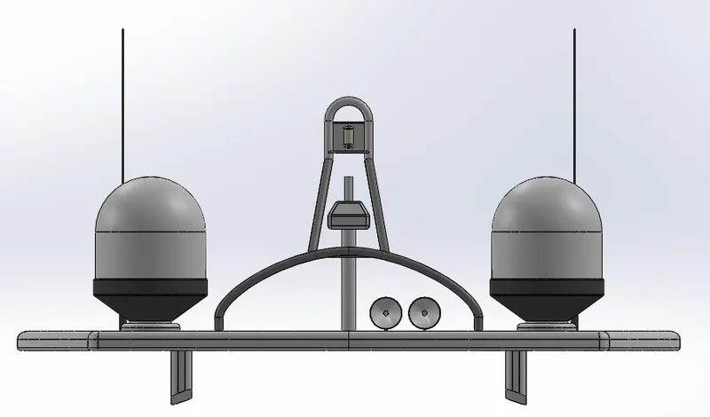
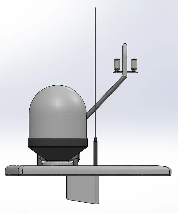
Rendered Image :
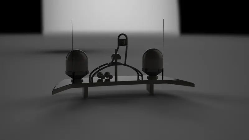
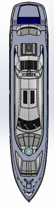
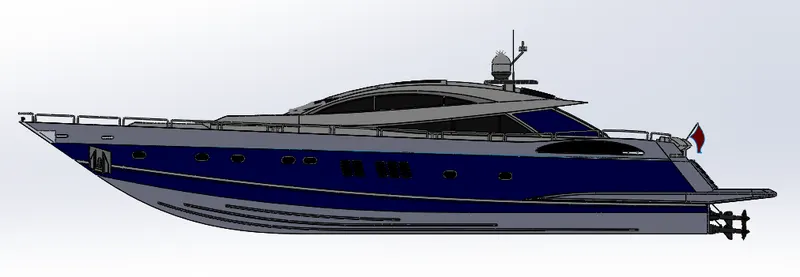
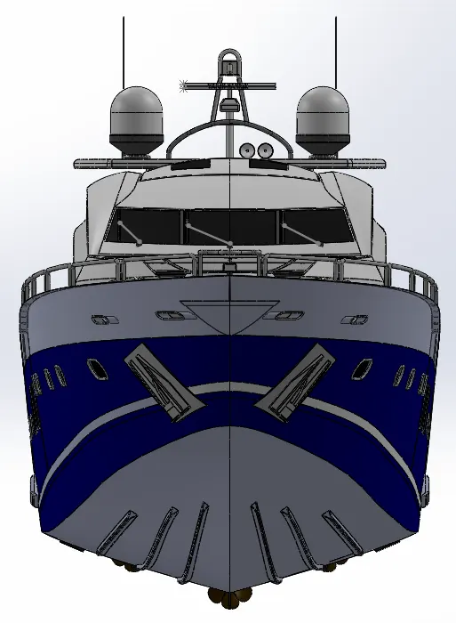
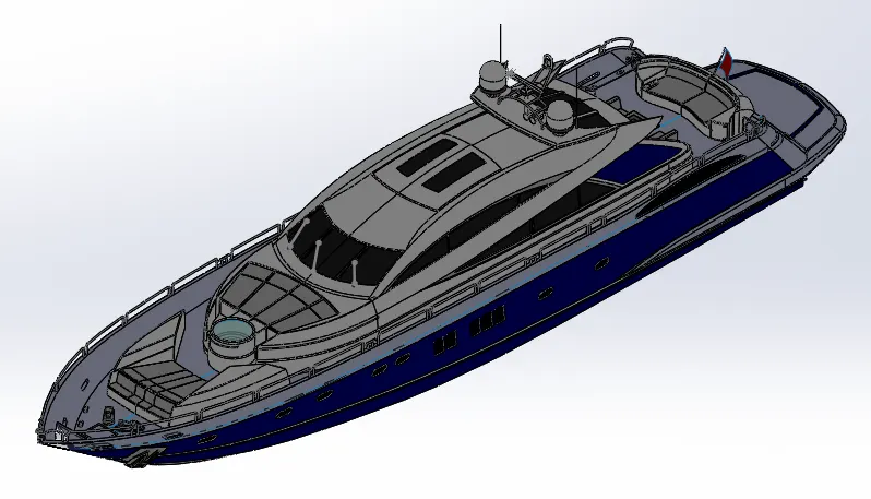
ASSEMBLY OF YATCH
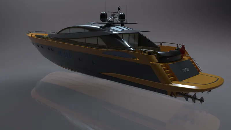
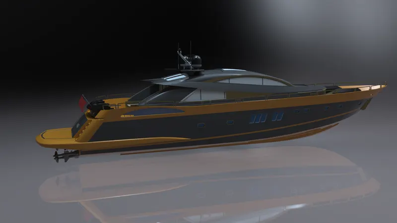
Modelled parts are assembled sequentially in an assembly area in order to get final yatch.
Insert Component : To add part into assembly area.
Mate : It is a geometrical relationship between the parts assembled. Various relations like parallel, perpendicular, concentric, distance, angle are included.
Move Component : To move the component within its degrees of freedom.
Rotate Component : To rotate a component within its degrees of freedom.
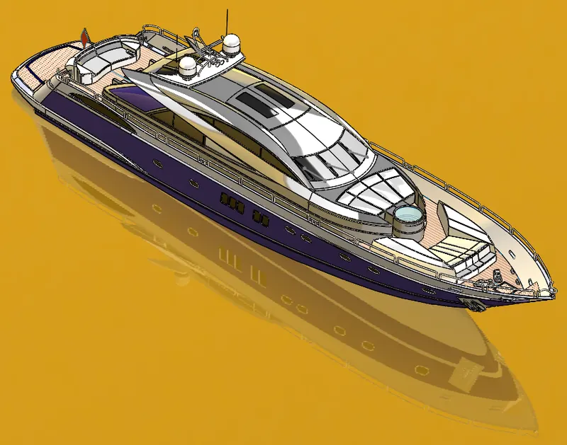
RENDERING :
It is a process of generating photorealistic and non-photorealistic image from a 2D/3D model by means of computer program. In solidworks there are two types : Photoview-360 and Solidworks Visualise.
Photoview-360 : It is a visualisation and render tool included in solidworks software. It provides high interactive environment for viewing designs and also to create photorealistic renderings.
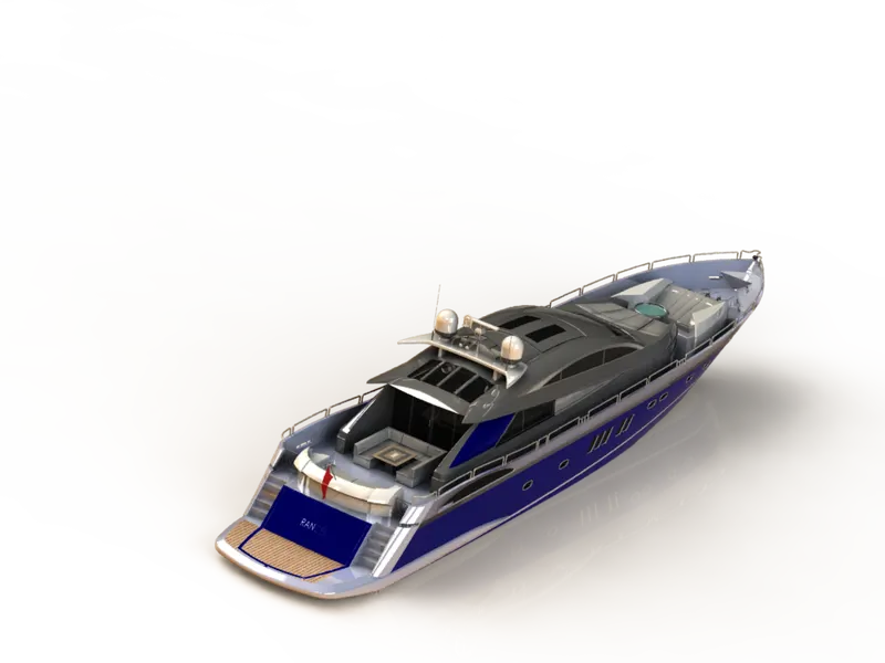
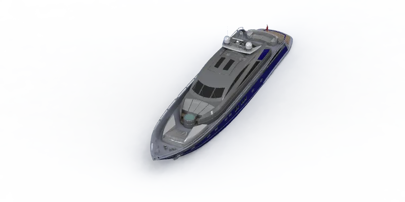
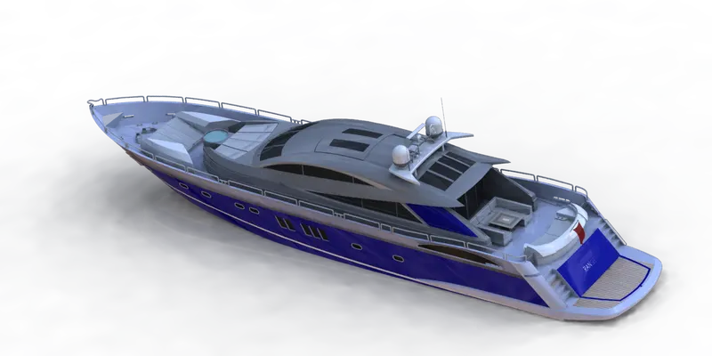
Solidworks Visualise : It is a software part of solidworks platform which allows users to create magazine quality images. It consists of Hd environment, appearances, backplates, camera which can be used suitably to make an object realistic.
CONCLUSION :
- Parts are modelled for the assembly of Yatch.
- Modelled parts are assembled sequentially with suitable mates to form Yatch.
- Decals, appearance are added to the Model.
- Model is rendered using Photoview-360 and Solidworks Visualise.