Radar Mast & Final Assembly of Yacht
PROJECT REPORT :
DESIGNING OF YACHT COMPONENTS, MODELLING, ASSEMBLY AND PHOTO RENDERING
The following model describes the part design, assembly and photo rendering.
Objective: In this project, the objective is to learn about how to design a model and gain knowledge of different tools used in solid works modelling, assembly and rendering of the yacht. The procedure of designing a yacht is explained below. Let us know the parts which are included in yacht.
The parts and process included in yacht designing are
1) Propeller
2) Radar
3) Blueprint set up
4) Hull
5) Garage door
6) Front seat
7) Middle seat
8) Rear seat
9) Superstructure
10) Radar mast
11) Assembly
12) Photo rendering
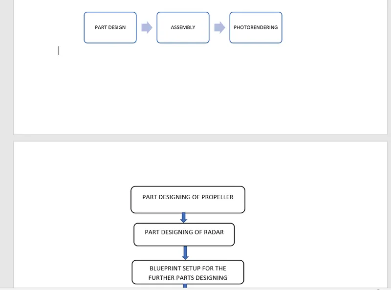
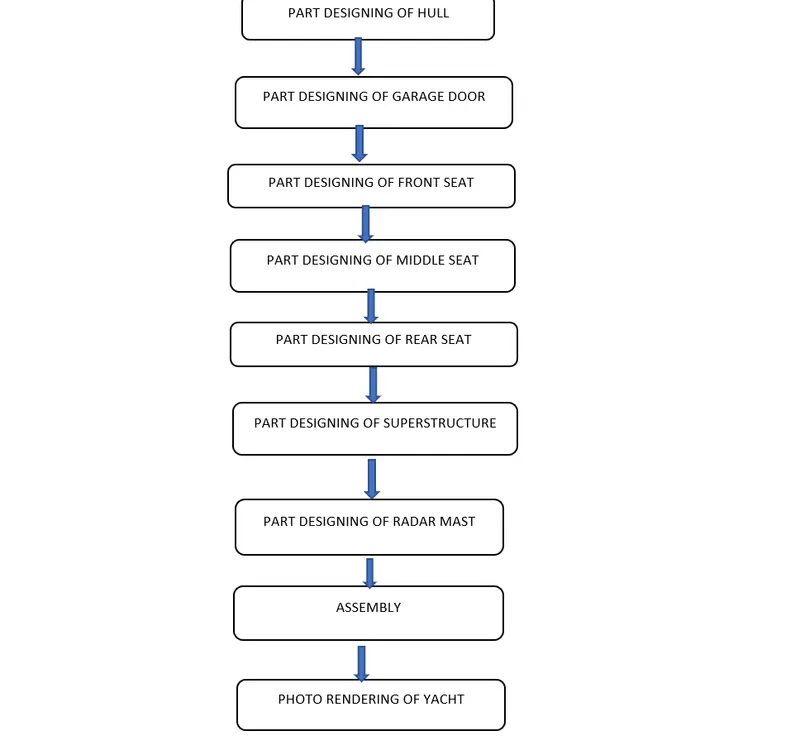
Firstly, the components mentioned above are designed and then the assembly is done. After the final assembly, photo rendering of the yacht is done to create a realistic view. The procedure of yacht design is explained briefly in the form of flowchart.
1-Propeller
The propeller is the primary connection between the engine and water. The propeller affects every phase of performance - handling, riding, comfort, speed, acceleration, engine life, fuel economy and safety. In determining boat performance, propellers are second in importance only to the power available from the engine itself. Without the propeller's thrust, nothing happens.
Part designing
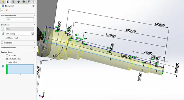
Create a new part. Draw a 2D sketch as shown in figure1 and use revolve feature. For revolve, select the axis of rotation and the sketch drawn.
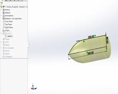
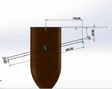
Draw a 2d sketch on top plane fig.2 and fig 3. Use solid loft feature for the fig below figures. For Solid loft, select the two sketches to create it into a single feature. Make sure the green balls are on same rectangle while using solid loft feature.
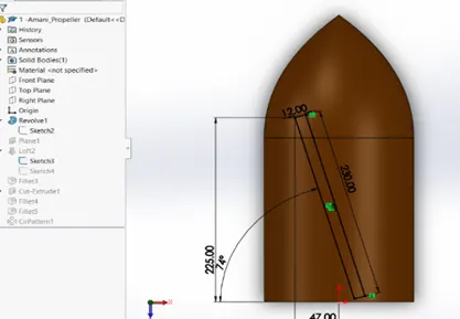
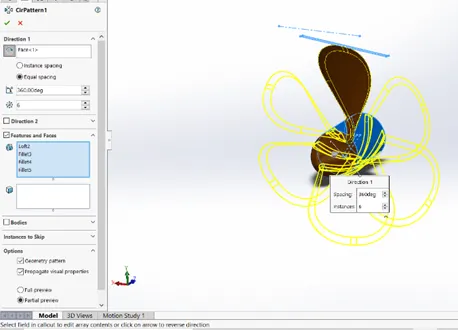
Then Circular pattern feature is used. Select the number of patterns required and the profile.
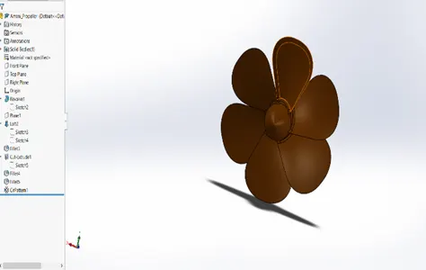
Add fillet on the edges of the loft. Draw the sketch and use extruded cut feature. Create a circular pattern of the created part. Change the color to the part as shown.
2- RADAR
Radars simply send the radio waves (within the range), and if there are any obstacles (ships or landmass) in between, then the radio waves get reflected back to the radar. Based on the time that took the radio waves to come back, it will calculate the distance and display the range on the screen.
Part designing- Create a new part. Start the sketch on right plane as shown in fig. and create an extrude and add fillet to the edges.
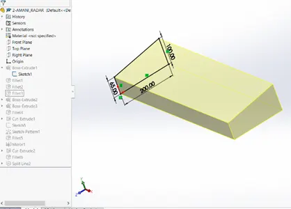
Select the edge of the extruded part and use offset entities to offset it with 3mm distance. Use extrude feature for this profile with a distance of 10mm and extrude it.
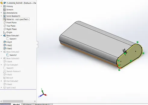
On the extrude part.select he face of and draw the sketch as shown and extrude it and add fillets.Select the profile and use pattern to create multiple bodies on the selected face and extrude it as previously.
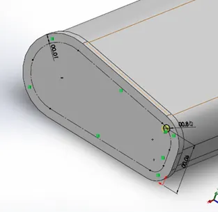
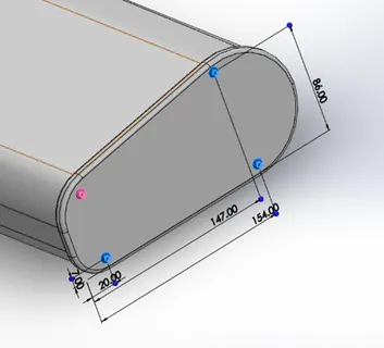
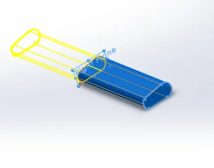
Mirror the radar by using right plane. Select the bodies to be mirrored option and select the body.
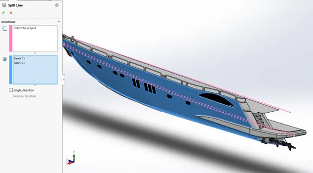
Add text on to the body. Select the split line feature, select the faces of the part to where the text should be projected on.
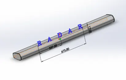
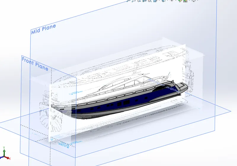
3- Add the blueprints according to the planes selected and give proper dimension as shown.
Create a new sketch on front plane. Go to Tool>Sketch picture. Browse the file and add the downloaded blueprint front view with proper dimensions and close the sketch and save it as BLUEPRINT_FRONTVIEW.
Select the right plane and create a 2D sketch. Browse and the blueprint side and add it to the plane with given dimensions and save the sketch as
Similarly, create a 2D sketch on top plane and add the sketch picture and save it as BLUEPRINT_BOTTOM VIEW. Later change the name of the top plane to bottom plane.
Create a new plane with an offset distance of 32920 mm from the front plane and save the plane as Back plane. Create a 2D sketch on back plane, add the blueprint-back sketch picture and save it as BLUEPRINT_BACKVIEW.
Create a new plane with bottom plane as reference with an offset distance of 10000 mm. Change the name to Top plane. Sketch on this plane, add the blueprint-top picture and save it as BLUEPRINT_TOP VEW.
Select the Midplane from feature tree and change the name of it to Mid plane.
After naming all the planes and sketches properly, arrange them in the following order and save the overall file as BLUEPRINT_SETUP.
Back Plane
Top Plane
BLUEPRINT_FRONTVIEW
BLUEPRINT_SIDEVIEW
BLUEPRINT_BOTTOM VIEW
BLUEPRINT_BACKVIEW.
BLUEPRINT_TOP VEW
4- Hull
Open the file blueprint-setup previously created and save the file as HULL.
Start sketching on the bottom plane and midplane as shown. Make sure the lines are similar with the blueprint and give proper relations and close the sketch with fully defined.
Create a 2D sketch on mid plane and bottom plane as shown with proper dimensions and make the splines look same as near to the blueprint setup.
Go to Projected curve. Insert>curve>projected curve. With the previous 2d sketches from bottom plane and midplane, select them to project a curve and click ok. i.e CURVE 1.
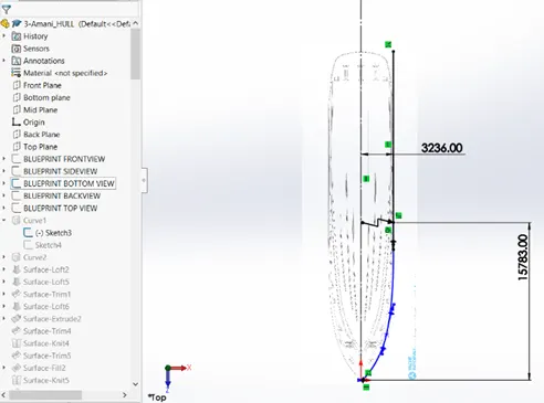
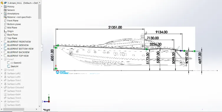
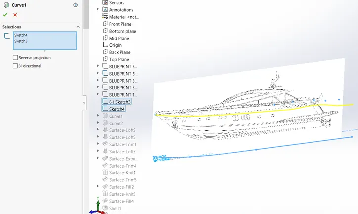
Similarly, draw the 2D sketches on bottom plane and midplane and select the profiles to generate a projected curve i.e CURVE 2
Create a new sketch on Back plane and midplane.
Go to Insert-Surface-Loft and use this feature to generate a surface. Select the curve 1 and curve 2 in the profile box as and remaining 2D as profiles as guide curves for the surface loft.
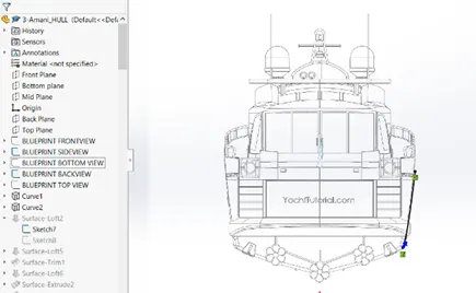
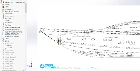
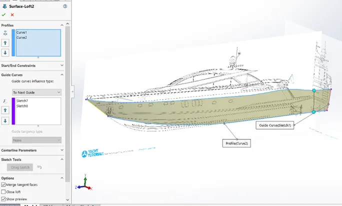
Sketch the 2D profiles and select them as profile and guide curve as shown and use the surface loft feature to generate a surface.
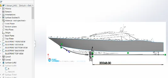
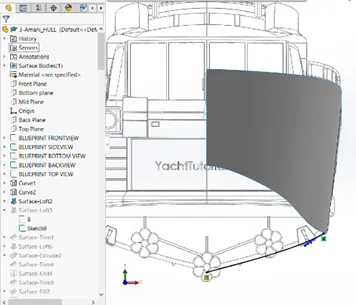
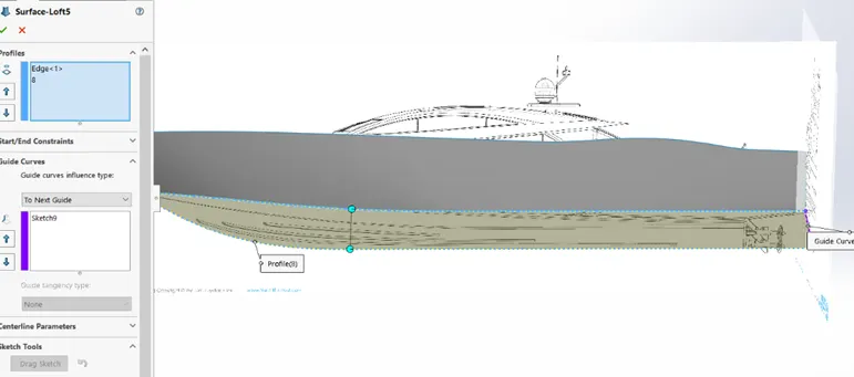
Draw a sketch on midplane. Go to Insert>surface>Trim. Select the sketch and remove the wanted part by selecting Removing selections.
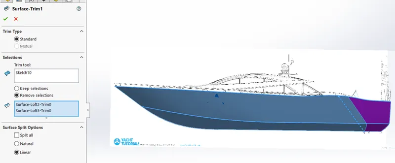
Sketch on the mid plane and draw the spline meeting as per the blueprint setup. Go to Insert
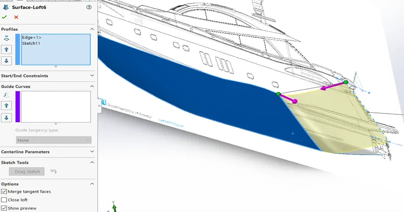
Surface extrude and surface trim features are used when required.
From Insert-Surface-Extrude, select the 2D profile and extrude it with the specific distance mentioned.
Go to Insert- Surface- Trim, select the remove selections and choose the parts to be trimmed.
After proper trimming, go to Insert> Surface>Knit, use surface knit tool to knit the surfaces with a knitting tolerance of 0.0025mm.
After the surface knit, it is important to notice that the edges are turned black because it shows the sign of proper knit.
For Surface fill, go to Insert- Surface- Fill, select the edges of the part to be filled and knit the surfaces of the hull with Surface knit feature.
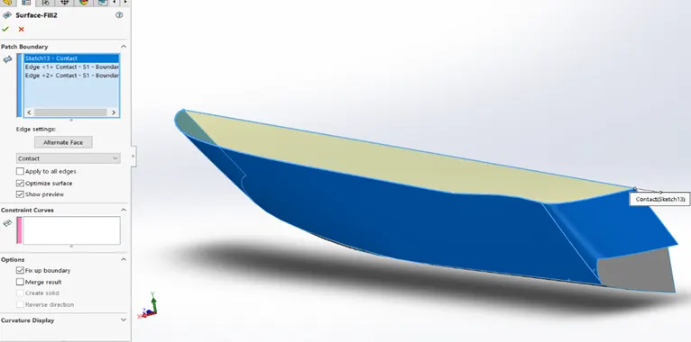
Create a shell after the surface knit, go to Insert-Features-Shell, select the faces of the hull and give 120mm value.
Draw the sketch on the midplane. Create and extrude of the shell. Go to Insert>Boss/Base>Extrude, click on Up to next and extrude it
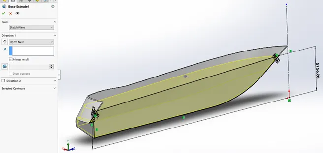
Draw the sketch on the mid plane with proper dimensions as shown and select extrude feature, select the sketch extrude it with proper distance.
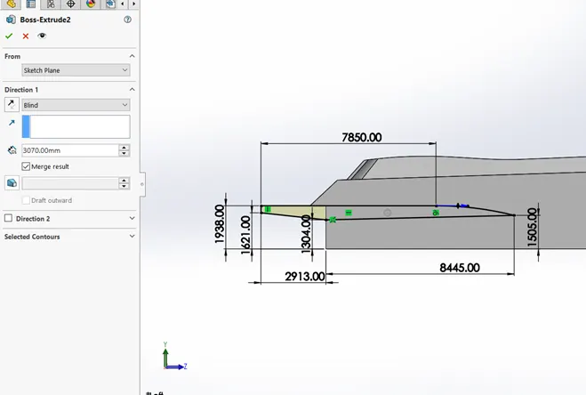
Create a new sketch on Bottom plane and draw the splines according to the blueprint. Go to Insert>Cut>Extrude, click on the sketch to be remove the unwanted part with a specific distance mentioned. Later add fillets and chamfer to the edges with given radius.
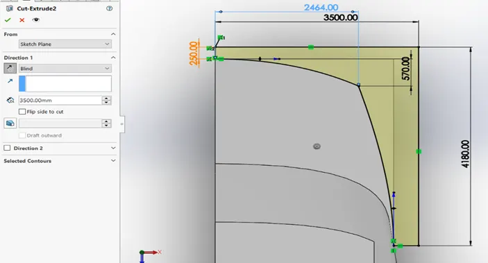
Cut Extrude feature is used for the following 2D sketches. These sketches are created on a new plane with an offset distance of 5000mm from Mid plane.
Go to Insert>Cut> Extrude. Change the distance and select the face for extrusion and select reverse offset with the mentioned distance.
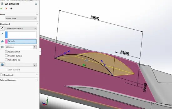
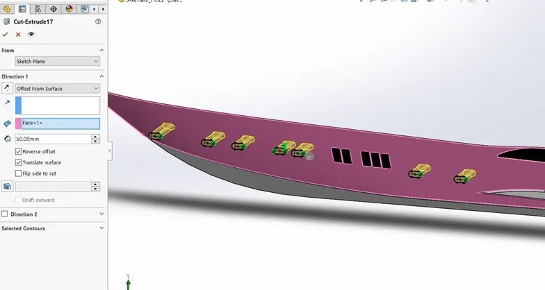
Create a new plane from bottom plane with an offset distance of 3000 mm. Draw the 2D sketch on this plane and use extrude feature. Give the distance for the sketch to be extruded and add chamfer to the edges.
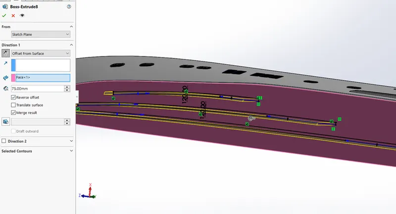
The 2D sketches are created and Boss extrude, revolve features are used for the following with proper given distance.
Select the sketch and extrude it to 30mm.
For revolve, select the line of axis for the part to be revolved.
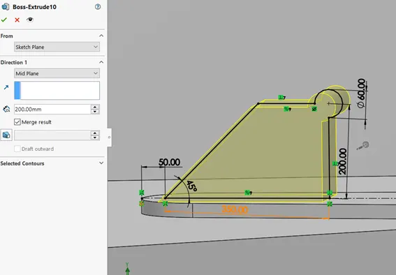
Select the sketch and extrude it with 200 mm by using midplane as direction 1.
Add fillets after applying the features
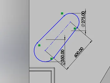
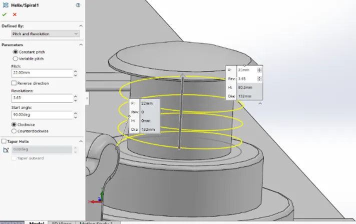
Create a 2D sketch and go to Insert>Curves>Helix/Spiral. Select the circle sketch and give pitch length and no. of revolutions and the angle for the helix to generate.
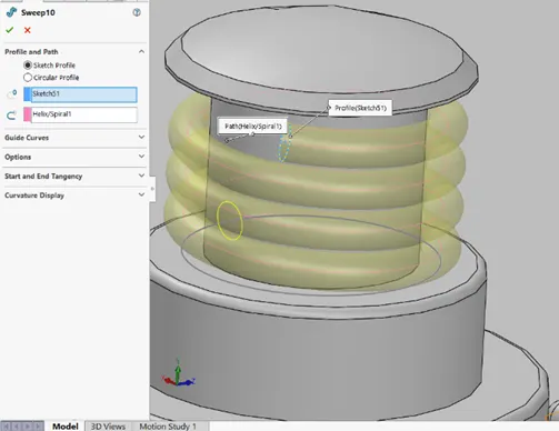
Create a new plane. Go to Insert> Reference Geometry>Plane. Select the end point of the helix and the edges to create a plane. Sketch a circle of 20 diameter and give Pierce relation to the circle and the helix.
Use Solid sweep feature, go to Insert>Boss/Base>Sweep, select the circle as profile and the helix as path to create a solid sweep.
Create a new sketch on Mid plane, offset the edge of the hull and draw the 2D sketch as shown and fix the sketch and save the sketch as RAILING_REFERENCE.
Create a new sketch on mid plane, go to Tools> Sketch Tools> Convert Entities here convert the railing of the reference sketch to convert entities.Add fillet to the edges.
Create a sketch on plane created, select Offset entities from the feature tab, offset the edge of the hull to 60 mm.
Use the sketches to project a curve, select Insert> Curve> Projected.
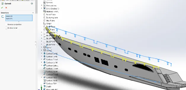
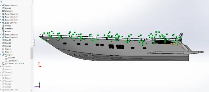
Create a new plane with the curve generated. Select plane form Reference Geometry, select the end point of the railing and the edge to create a plane. Create a 2D sketch on this plane, a circle of dia 60 mm and close the sketch. Use solid sweep form the feature tab, select the circle as profile and the curve generated as path for the sweep to generate.
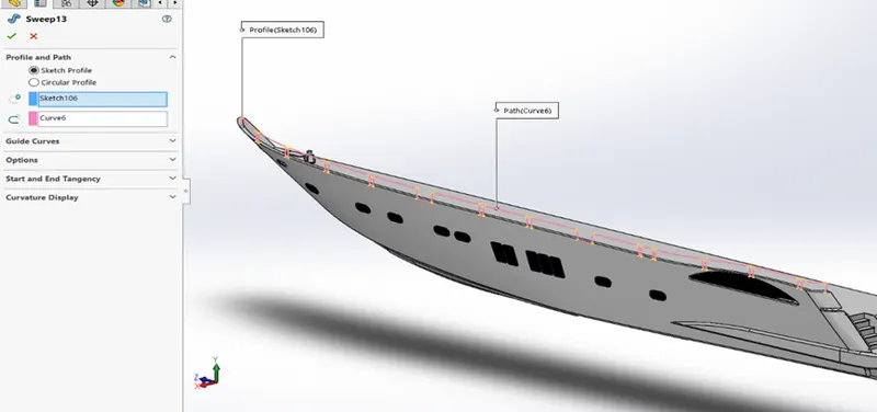
Select the surface of the hull where the sketch is to be drawn.Here extrude and revolve features are used for the following 2D sketches. After applying the features, add filleys to the edges.
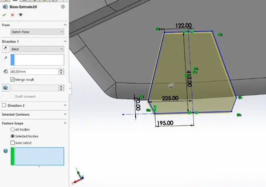
Create a sketch on mid plane as shown and select the extrude feature for the extrusion of the sketch with a given dimension.
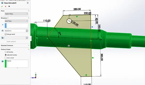
For the garage door,
Create a sketch on mid plane. Select the Insert>Cut> Extrude, give the distance and enable thin -feature with one-direction option with thickness 5 mm.
Convert the above sketch into convert entities. Create an extrude cut, select this sketch and give distance of 5mm.
For splitting the garage body from the hull, go to Insert> Features> Split enable consume cut bodies option. By selecting the cut extrude part it turns into pink and save the part as Garage_Door.
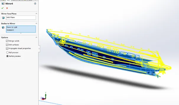
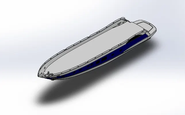
The split line feature is used to separate the part from multiple surfaces. Mirror the bodies of model along midplane and full model of hull is created.
Change the appearance of the hull as needed for different parts by selecting Appearance button.
5- Garage door
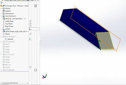
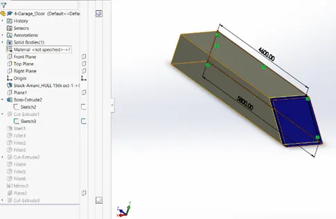
Sketch on the surface selected and extrude cut it.
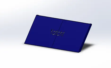
Create a shell with the dimensions given and add fillets. Mirror the created part and select sketch entities -text and add the text and extrude cut it onto the part created. Change the appearance of garage door.
4-Front seat.
Open the blueprint setup and save the file as Front seat. Go to the Insert>Part. Select the Hull part and insert the surface bodies of hull. Create a new part and save it as front seat. From the hull, select surface bodies of hull and insert it.
Create a sketch on the deck and on a new plane with given dimensions and close the sketch.
Go to Insert>Surface>Sweep, select the sketches for profile and path to create a surface sweep.
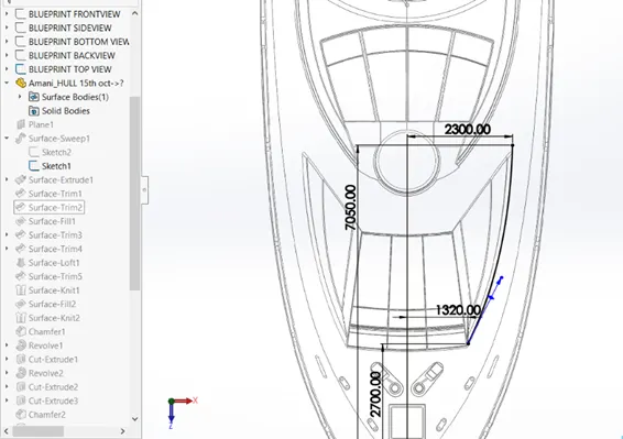
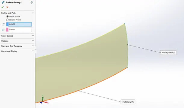
Create a sketch on the deck, draw lines as shown and use surface extrude feature. Go to Insert>Surface>Extrude, select the edge and extrude it up to vertex. Fig. 1 and 2.
After the extrusion, select Surface Trim from Insert>Surface>Trim, select the areas to be removed from the surface sweep.Fig.3
After trimming, fill the gap by using Surface fill. Go to Insert>Surface>Fill and select the edges of the part to be filled. Fig 4
Fig 1.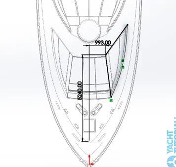 Fig 2
Fig 2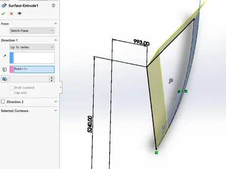 Fig 3
Fig 3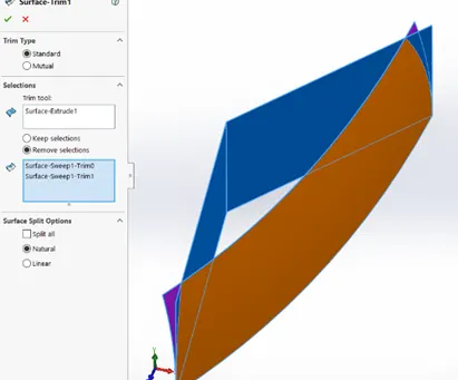
Fig.4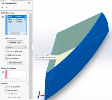
Create a new sketch on the deck with reference to blueprint, draw the spline and add dimensions and close the sketch. Use Surface Trim feature, click on Keep select selections and select the area. Fig 5
Create a new sketch on Midplane, draw a line with distance of 250 mm. and exit. Select Surface Trim and remove the unwanted area. Fig 6
After getting the required profile, use Surface Loft feature to fill the area. Go to Insert>Surface>Loft,
select the profiles and click ok and use surface trim to remove the extra surface. Fig 7
After applying all features, use Surface Knit to fill the gaps, select the areas and give knit tolerance of 0.0025 mm and apply chamfer.
Fig 5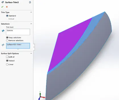 Fig 6
Fig 6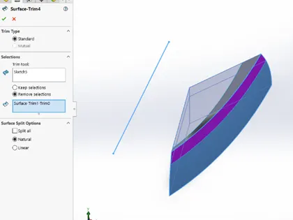 Fig.7
Fig.7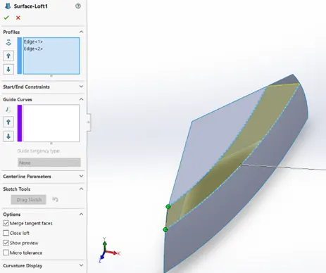
Create a new sketch on the surface, go to Insert>Boss/Base>Revolve, select the axis of revolution and give 10 degrees direction angle. Fig 8
Create a new sketch on top plane as shown and select the Cut Extrude feature and give distance of 6000 mm. Fig 9.
Fig 8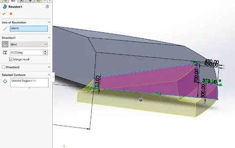 Fig 9
Fig 9 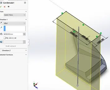
Create a new sketch as shown, go to Insert>Boss/Base>Revolve, select the axis to revolve
And give angle of 10 deg and select the sketch in selected conoturs. Fig 10
Select the previous cut extrude profile and do and extruded cut with 6000 mm distance.
Draw the profile osn the face selected and create an extrude cut with a distance of 5 mm.
Select the All Bodies option.After the cut extrude apply chamfer. Fig 11.
Fig 10 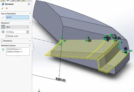 Fig.11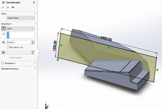
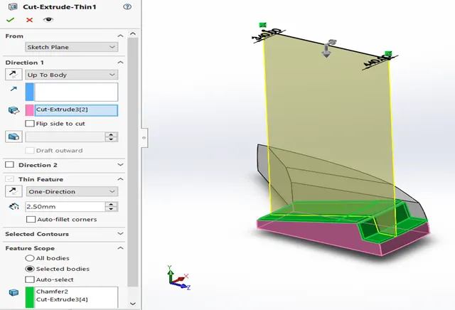
Create a new sketch on top plane, select the cut extrude enable thin-feature and give thickness of 2.5mm and select the body up to where it should be extruded. Apply fillets.
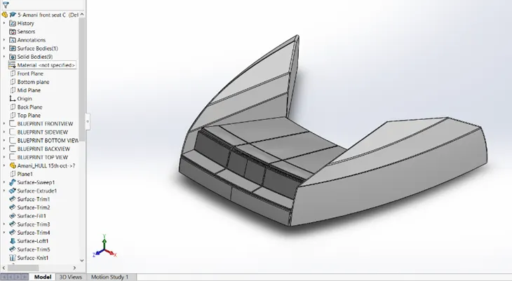
Select Mirror feature, select the bodies to be mirrored along the midplane.
Change the appearance of the parts individually.
5- Middle seat
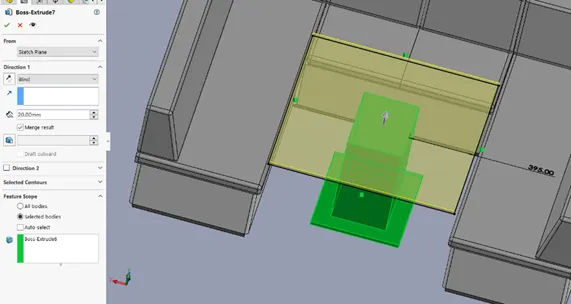
Open the blueprint setup and import the hull-deck surface for the reference to draw sketch.Create a sketch on the deck and select extrude feature and give a distance for the extrusion.
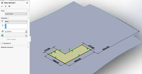
Select the surface of the extruded part and a sketch on it.Use extrude feature, select the slketch and give the distance mentioned.
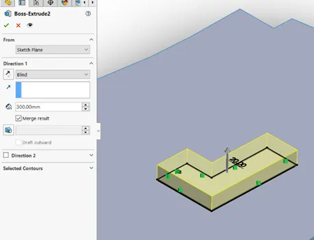
Create a new plane on the surface with an offset distance of 5mm.Draw a sketch on this plane and extrude it with the given distance.
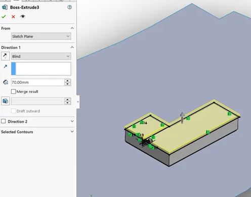
Create a new plane on the surafce generated, draw a sketch and extrude it.Apply chamfer to the edges with distance-distance option and add fillets.
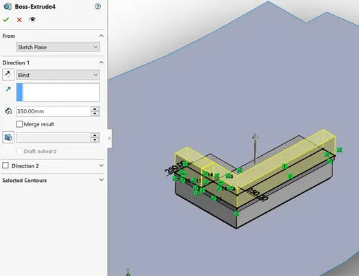
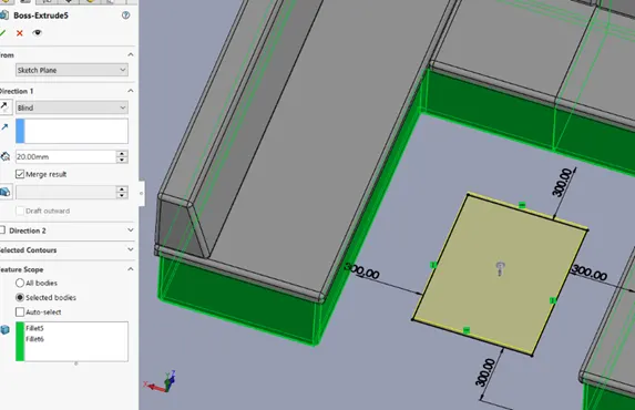
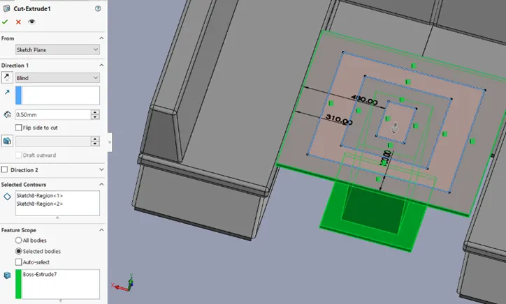
Create a new sketch on the deck as shown and use extrude feature for the profile.Draw a sketch again on the suface and select cut ectrude feature and select the regions in the selected contours.Apply fillet to the edges.
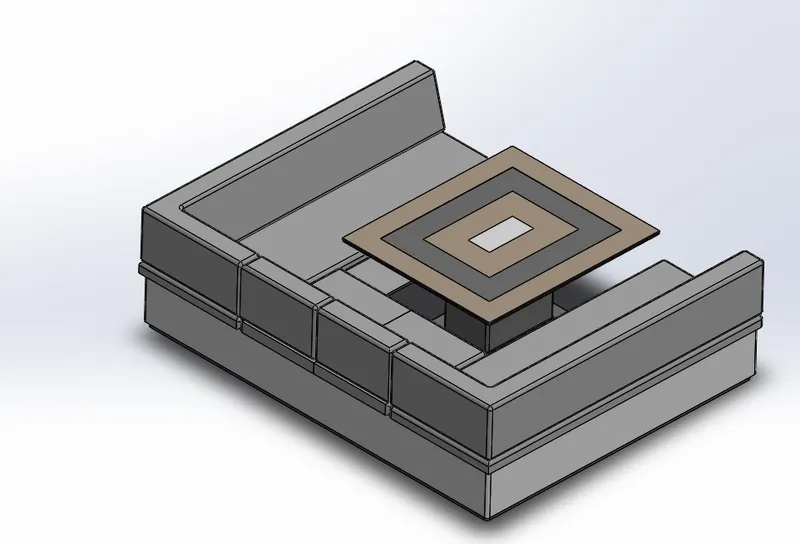
Change the appearance of the parts as required.
6- Rear seat
Create a sketch on Mid plane with reference to the inserted deck surface body.
Create a new plane and draw the profile as shown.Select Surface Sweep from Insert>Surface> Sweep and select the sketches created as profile and path.
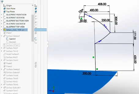
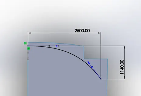
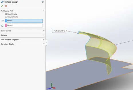
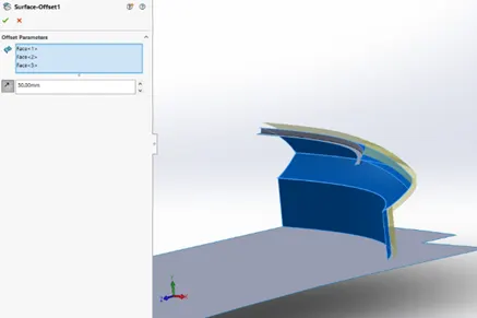
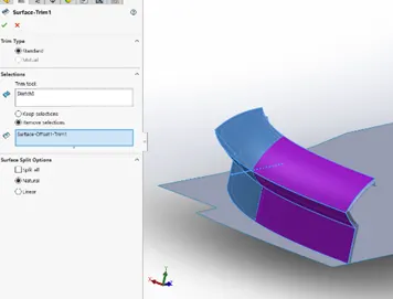
Go to Insert>Surface>Offset, select the blue surfaces and offset it with a distance of 50mm.Create a 2D sketch on plane 1 and use this sketch for trim.Select Surface Trim feature and select the areas to be removed.Repeat Surface trim again.
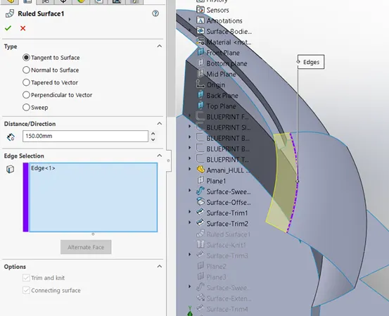
Go to Insert>Surface>Ruled surface. Select the edge and give the distance of 150 mm and select Tangent to surface option.
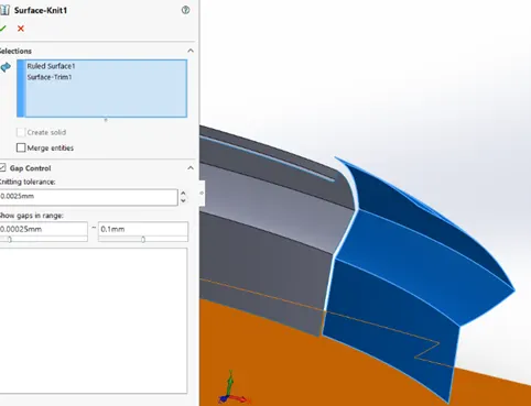
From feature tab , select Surface Knit and give the knit tolerance and select the areas to be knitted.
Create a new plane for the sketch, draw the sketch and use surface sweep feature for the profile.Extend the edge of the surface sweep with a distance of 200 mm and trim the area to be removed with the help of Surface trim feature.
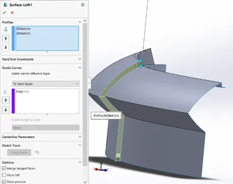
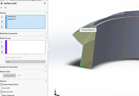
Create a 3D sketch and convert the entities of the edge and repeat for the other edge aswell. Go to Insert> Surafec>Loft, select these two profiles created for the surface loft.
By using Surface knit, select the areas and give a tolereance of 0.0025 mm.
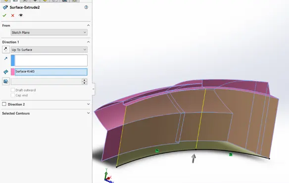
Draw a sketch on the deck surface, select convert entites and select the two edges and create a surface extrude with Up To Surface option.
Draw a 3D sketch by using convert entities for both edges.Use Surface Loft feature and select the 3d sketches.Knit the areas with surface knit feature.
Similarly, create a surface loft for the bottom gaps aswell.Surface Knit all the areas with the given tolerance.After selecting the areas,if every edge is knitted properly theb try to form solid option will be shown.Select the option and create a solid body.
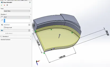
Draw a sketch on deck surface as ashown and use extrude feature and give a distance.
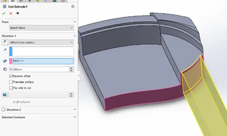
Draw a sketch on front plane, select Insert>Cut>Extrdue feature, select offset from surface and give distance.
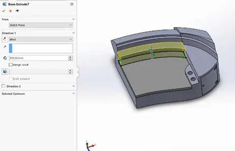
Apply chamfer to the extruded parts.Go to Insert>Features>Chamfer, select distance-distance option and give the value.Apply fillets for the rest of the edges with given value.
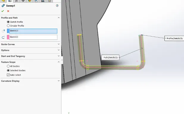
Create a new plane and draw the sketch.Create another plane with the previous sketch as reference.Draw the circle of 40 dia.
Select Solid sweep, select the circle as profile and the 2D sketch as path and sweep is generated.
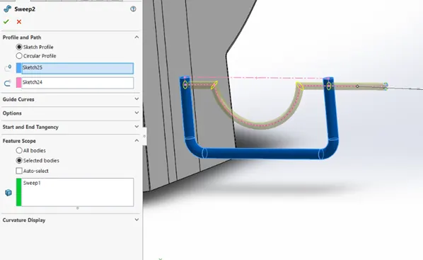
Create a new sketch on plane 5 as shown.With this sketch reference create another plane and draw a circle of 30 dia.Select solid sweep feature, select the profiles created for the sweep.
Go to Insert>Pattern/Mirror>Mirror, select the bodies and mirror it and the railing part is created.
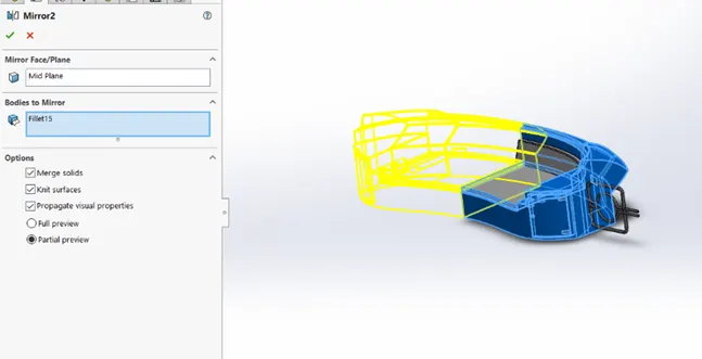
Mirror the rearseat created, selecte the bodies and mirror them along the Midplane.Select merge solids, knit surfaces option.
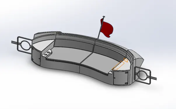
Change the appearance of the rear seat.
5-Superstructure.
Open the blueprint set up and create a new part and save the file. Insert the surface bodies of hull.
Create a sketch on the deck surface and make it look similar as blueprint. Go to Insert>Surface>Extrude, select the sketch and extrude it to a given distance.
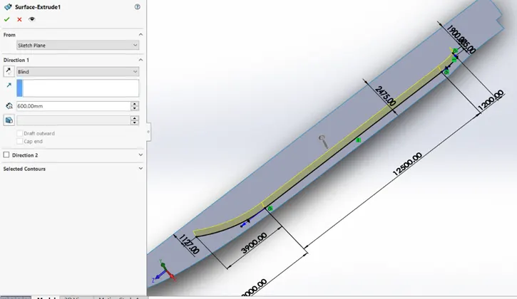
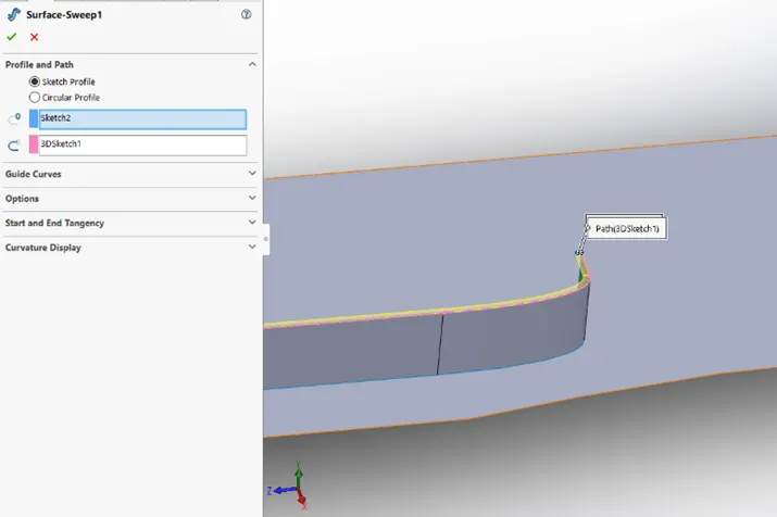
Create a new plane on the edge and draw a line of 50mm.Create 3D sketch, select the edge and make it into convert entities and close the sketch. Generate a sweep with the previous profiles.
Apply surface knit with a tolerance of 0.0025 mm. Apply fillet of 35mm to the edge.
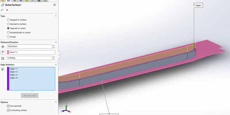
Select the edge of the sweep, use Ruled Surface feature, select Tapered to vector option and give distance and change the angle to 5 deg. Make the surface tilted towards inwards.
Create a new sketch on Mid plane, select surface trim feature, with the sketch remove the unwanted area.
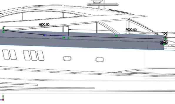
Create a new sketch on Mid plane and Top plane as shown. Create a projected curve with the created two sketches.
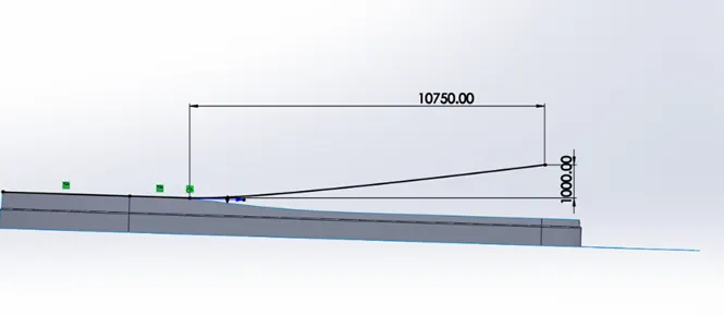
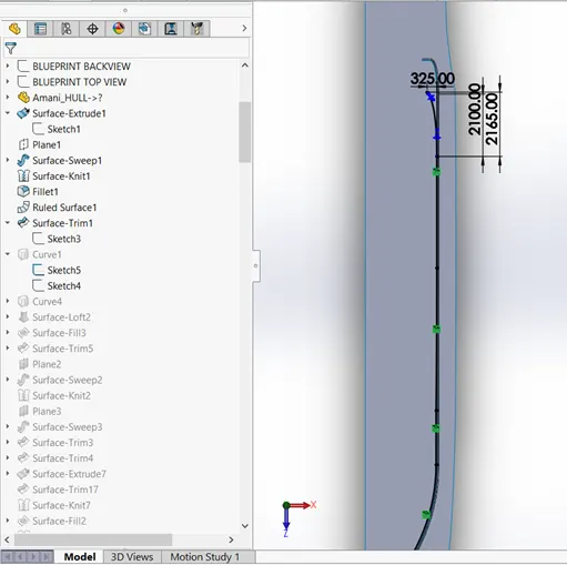
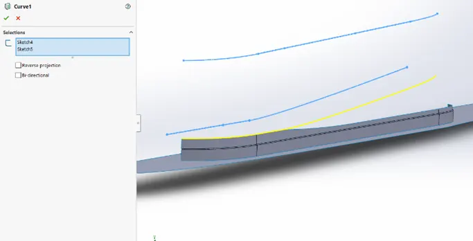
Create sketch on Top plane and mid plane. Go to Insert>Curve>Projected, select the two profiles and create a curve.
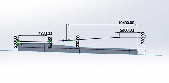
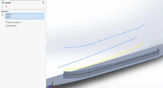
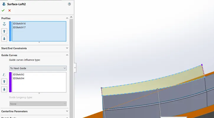
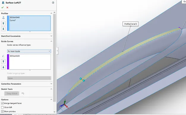
Create four 3D sketches by using previous curves generated. Use surface loft, select the 3D sketches for the profile and guide curves.
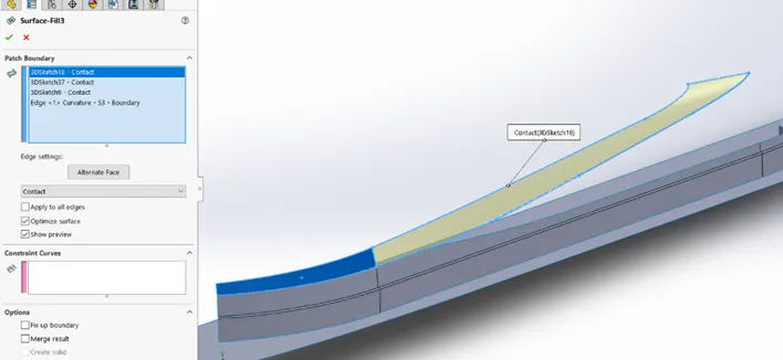
Go to Insert>Surface>Fill, select the 3D sketches, a yellow-colored surface shows up.
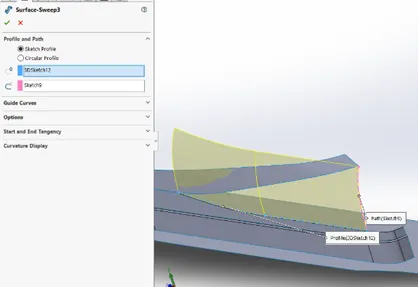
Create a new plane and draw the sketch. Select this sketch for the surface sweep. Create a sketch on the mid plane, select surface trim feature, with reference as this sketch select the area to be removed.
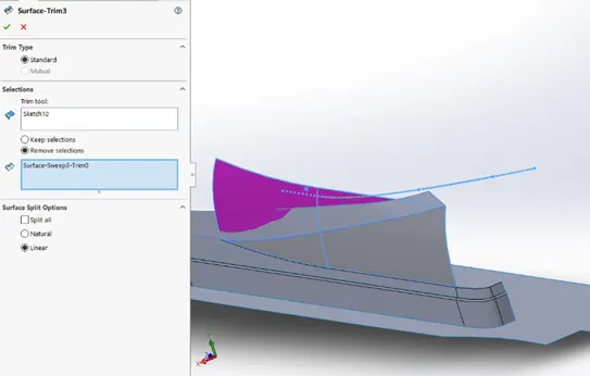
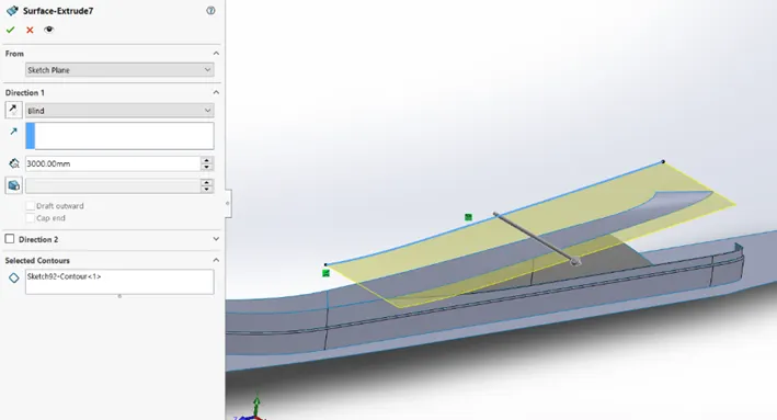
Sketch on the Mid plane and select this sketch and surface extrude it with a given distance.
Surface knit all areas with the tolerance mentioned.
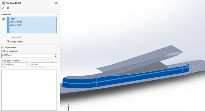
Create a sketch on Mid plane and Top plane. Select the profiles to project a curve.
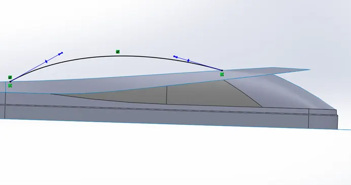
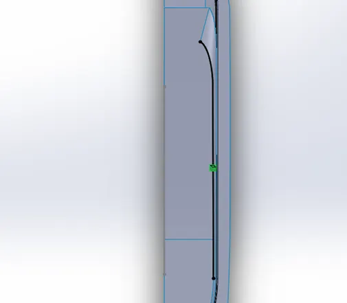
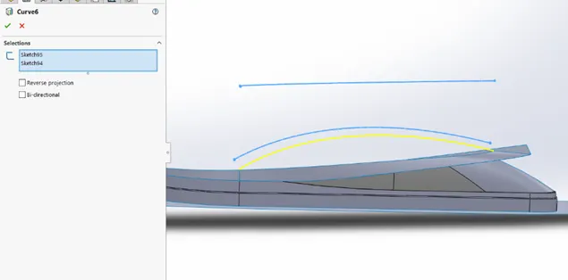
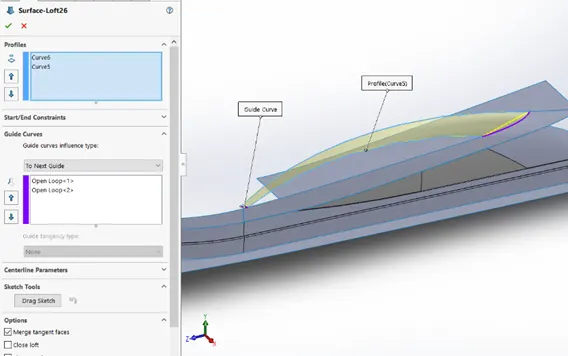
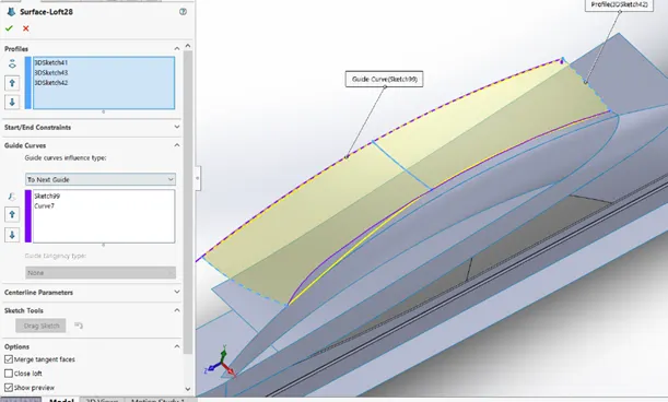
Go to Insert>Surface>Loft, for the surface loft feature select the profiles and guide curves.
The loft feature creates a shape by making transitions between multiple profiles and guide curves.
Apply surface loft for the following sketches as well.
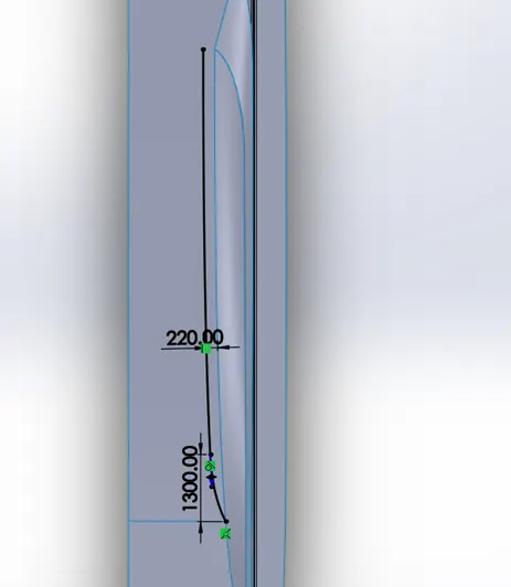
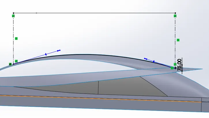
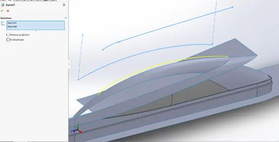
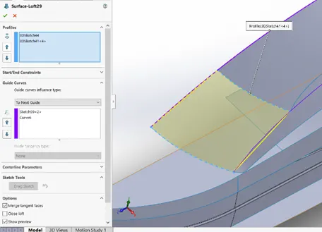
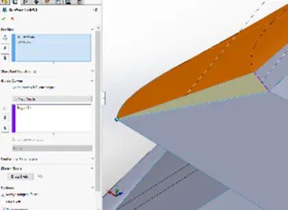
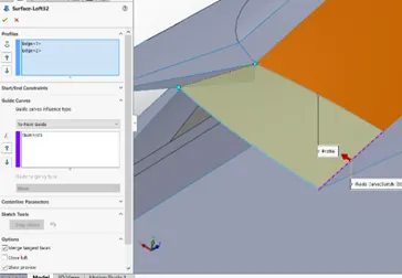
Select the surface of deck and draw the sketch as shown and surface extrude it. After surface extrusion, trim the unwanted part with Surface trim feature.
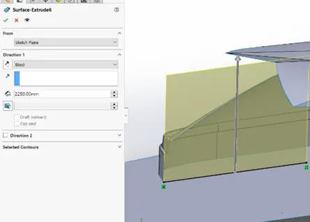
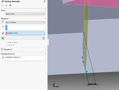
Select the edges and surface extrude it. Remove the area with the surface trim feature.
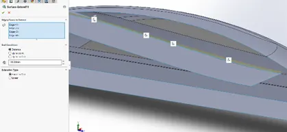
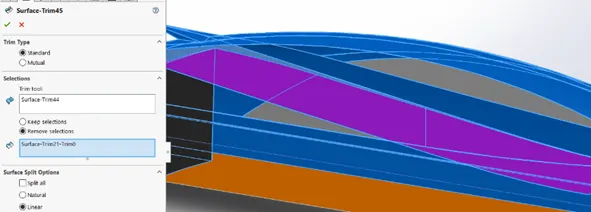
Create a sketch on Mid plane and select the surface sweep feature, select the profile sketch the edge as path for the sweep.
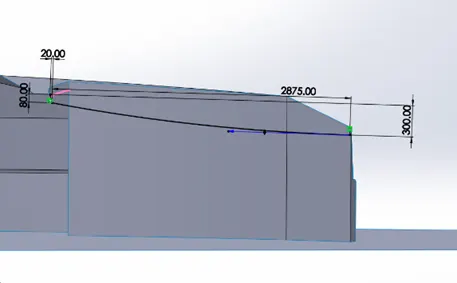
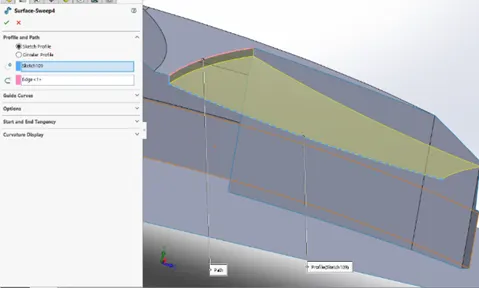
Draw the sketches and surface extrude it. Remove the area as per the required design with the surface trim feature.
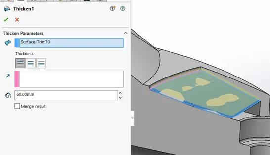
Select the area and offset it to a distance of 5 mm. Select the offset part and select Thicken feature and give value as mentioned.
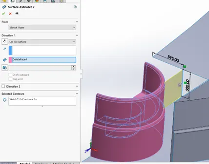
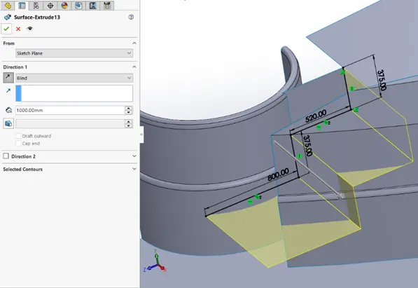
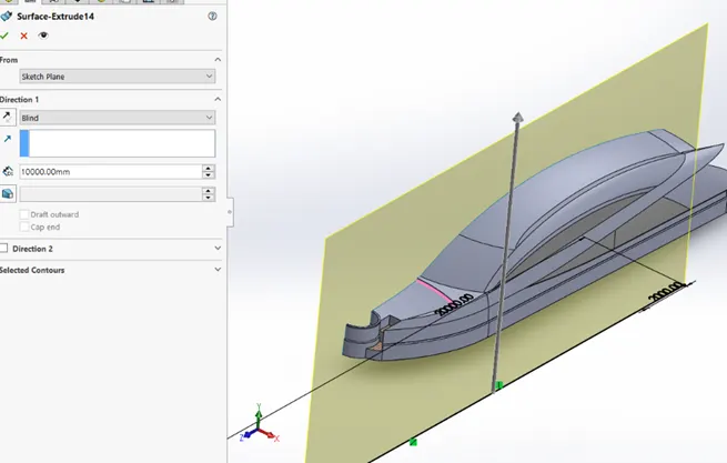
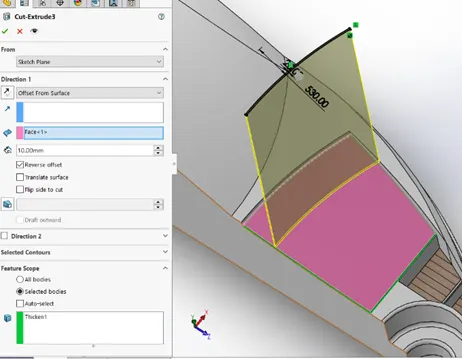
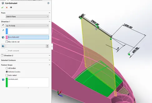
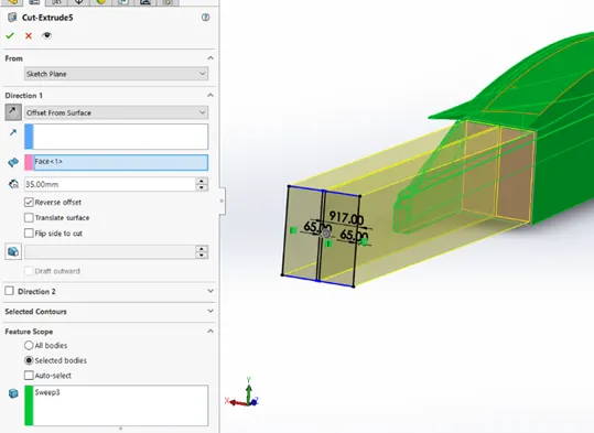
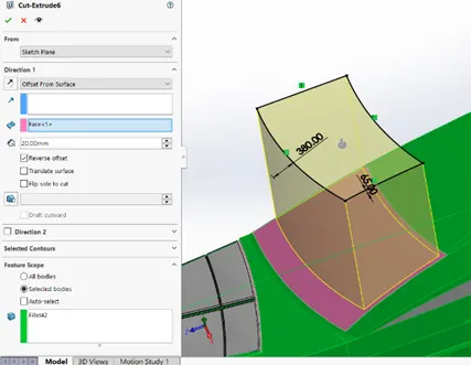
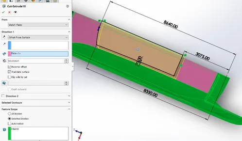
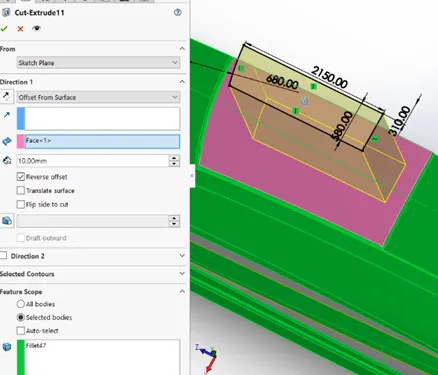
Create sketches on different planes according to the part to be designed. Select the sketches to remove the material from the solid body. To remove material, select the cut extrude feature and give distance and select reverse offset when it is required.
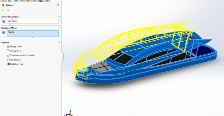
After the part designing has finished, mirror the bodies along the mid plane and change the appearance of the part with the colors mentioned.
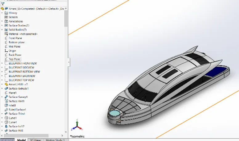
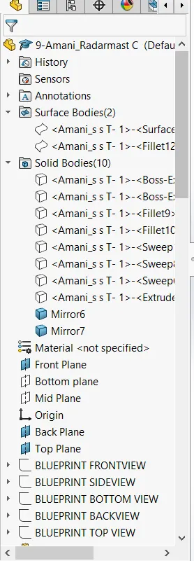
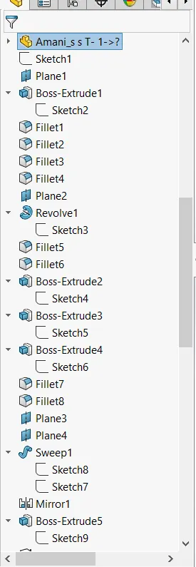
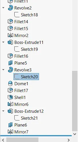
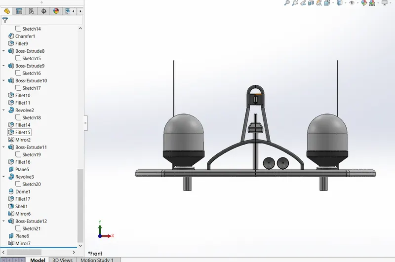
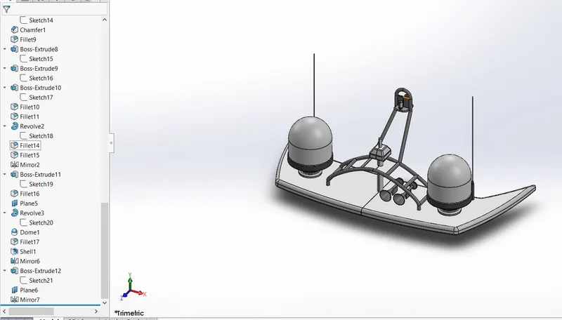
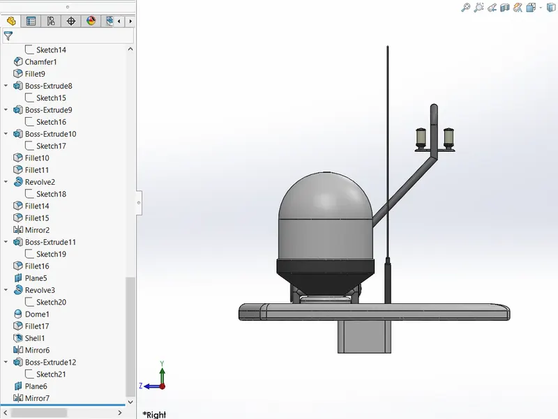
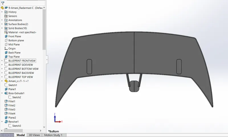
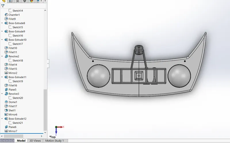
6- RADAR MAST
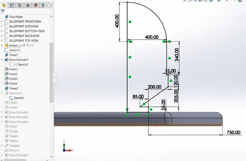
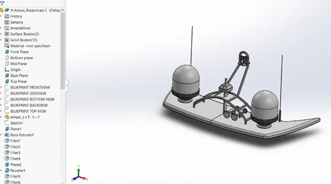
Open the saved blue print file. Import the radar-mast reference from the previous saved file.
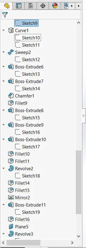
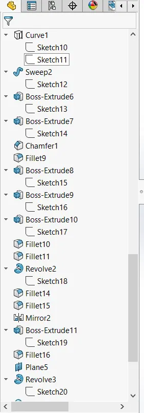
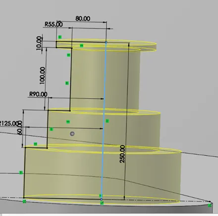
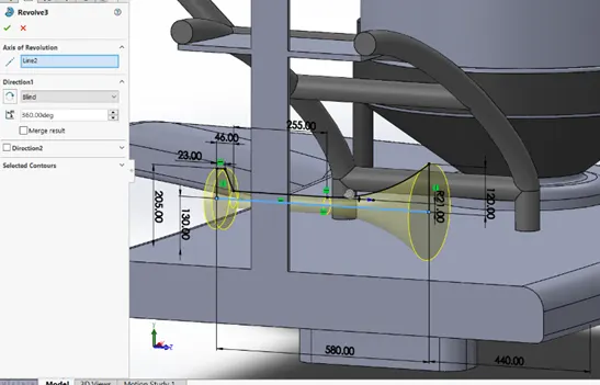
Use this surface body as reference and start the 2D sketch as given and use extrude feature. Create a sketch, go to Insert>Boss/Base>Revolve, select the line of axis and select the sketch to revolve.
Apply fillets where necessary with given dimensions.Change the appearance of the parts.
ASSEMBLY AND PHOTO RENDERING
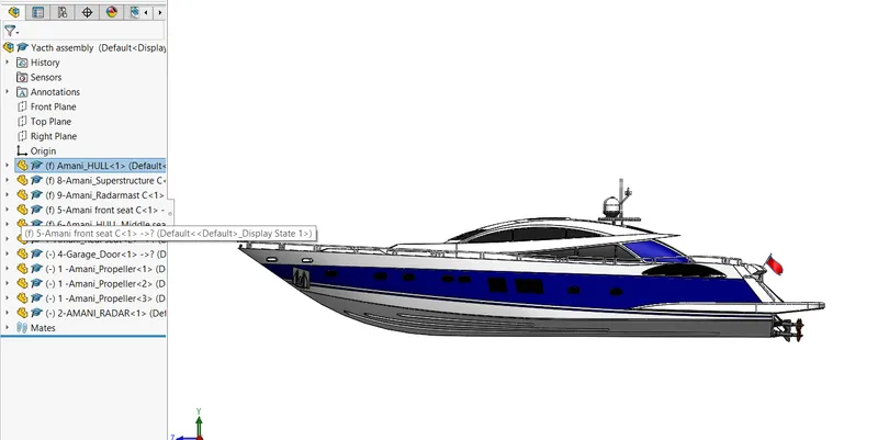
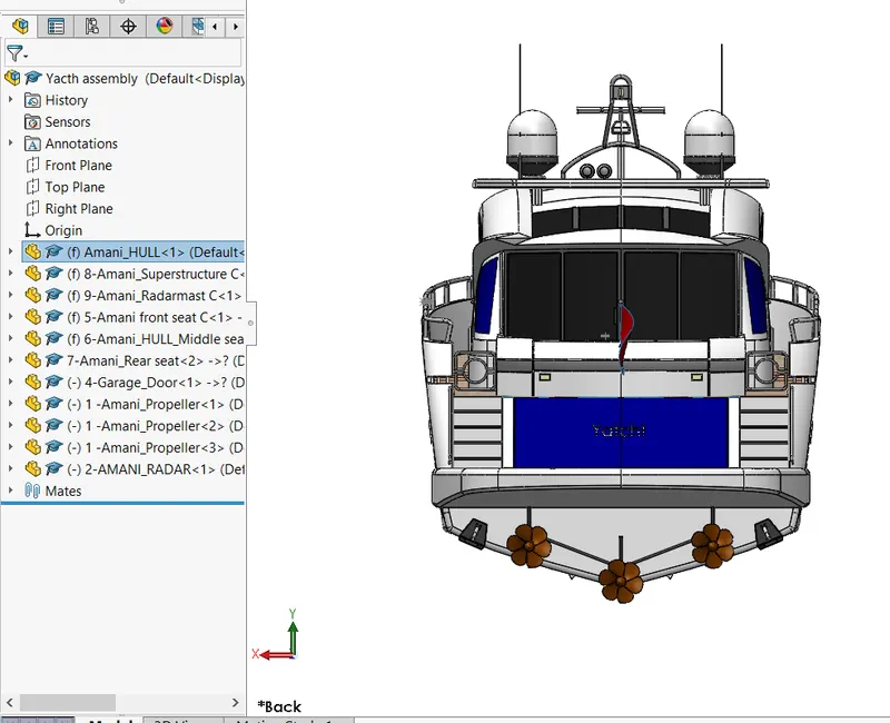
ASSEMBLY
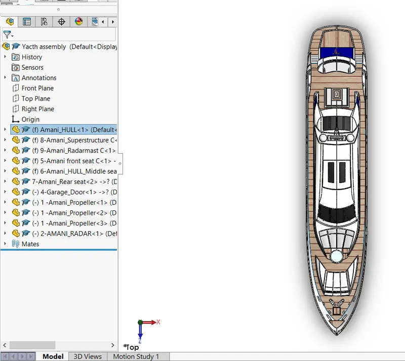
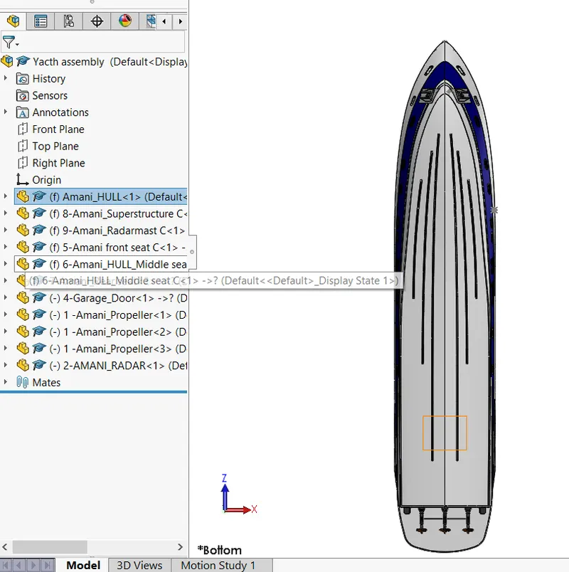
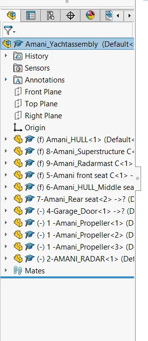
For the process of assembly, go to Insert>Existing component, firstly insert the existing individual parts of the yacht. While importing the parts, they are placed accordingly with respect to the given dimensions because for all the parts the hull-deck surface is used as reference. So, they get automatically placed. The proper mate relations like coincident, concentric etc are given to the parts where there is a gap or assembly is not done.
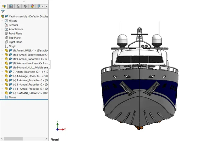
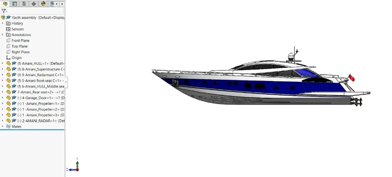
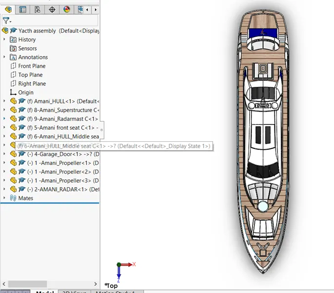
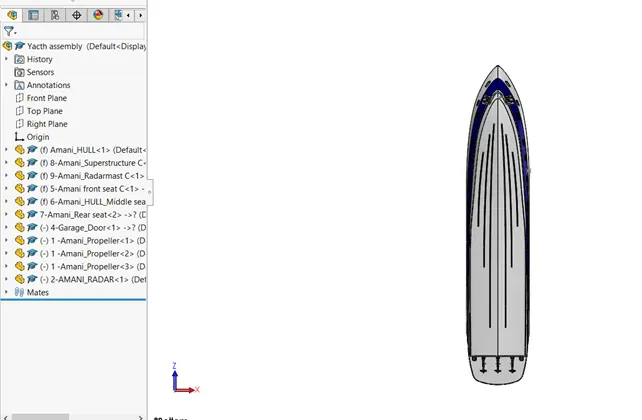
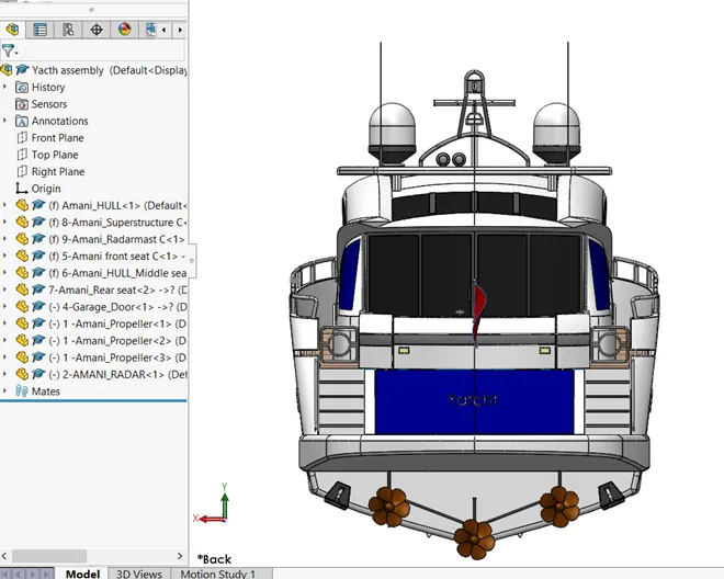
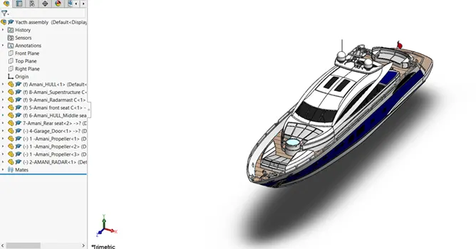
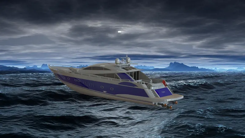
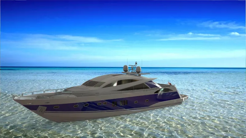
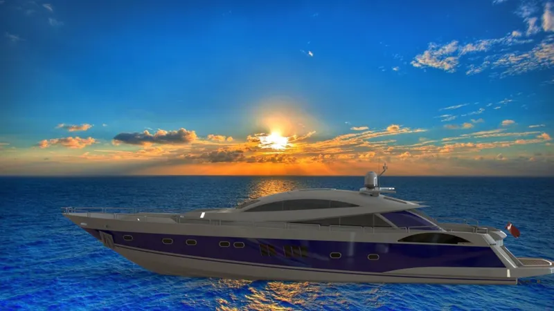
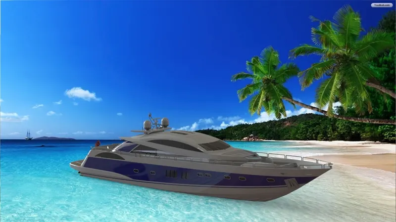
Photo rendering gives the realistic view of the created model where the image shows appearance, lighting, scene and decals included.
After the assembly of the yacht, add the photo view 360 to the feature tab. It helps to show the rendering images with realistic environment and visualization of the design created.
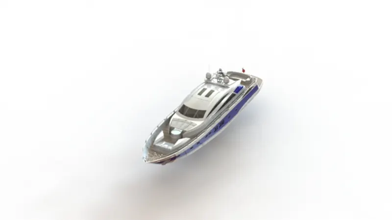
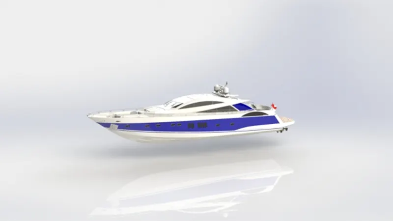
CONCLUSION:The designing of yacht is done smoothly with the help of solidworks features even though the complexity of designing yacht make it looks difficult initially.The knowledge of rendering helped to visualize and get a realistic view of the model to be brought into real environment.Mainly the knowledge gained while designing yacht is, the exposure of when to use different features and tools to make the design and edit parts efficiently are known and gained knowledge in part designing, assembly and rendering.