Radar Mast & Final Assembly of Yacht
Title:
To model and assemble of an Sunseeker Predator Yacht using Solidworks.
Objective:
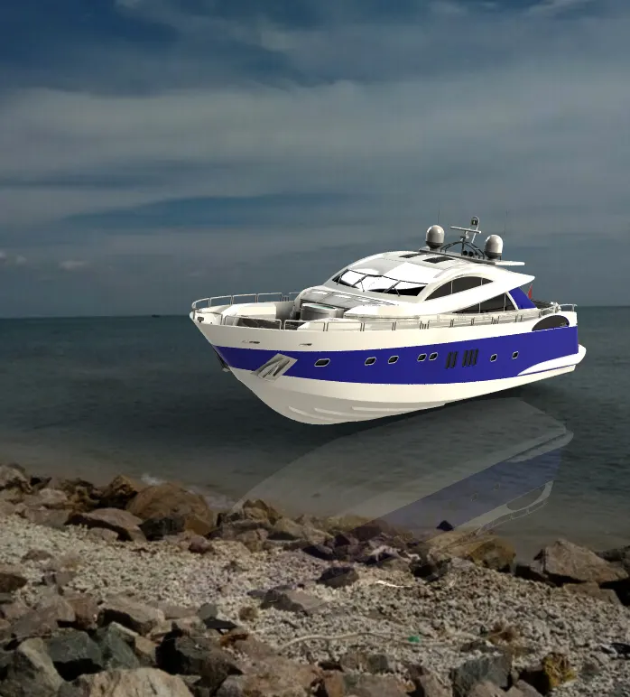
The objective of this project is to design and model all the parts of an Sunseeker predator Yacht and assemble it to create the Photo-Realistic rendering of the Yacht.
Introduction:
In this project the Sunseeker predator Yacht was taken as a conceptual model, to understand the 3D modelling methodology of solid modelling and surface modelling. Every part of the yacht was designed and modelled by using SOLIDWORKS. THen the modelled parts are assembled to create a Photo-Realistic rendered image of the yacht.
Design Methodology:
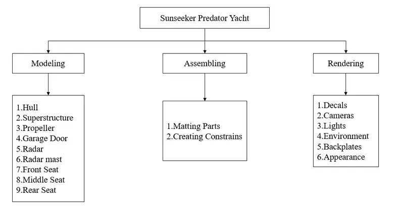
Common Tools used in modelling of Yacht:
Plane: Here the section view of the model is to be sketched.
Sketch: It gives the work base to create 2D & 3D sketches.The sketch is a 2D representation of the model.These are known as Entities in Solidworks.e.g.: Line,Rectangle,Spline,Circle,Arc etc
2D sketch: 2D sketch is the basic command which takes one to the sketching templates. It is where we make the sketches required to make solid bodies or parts. We have to select a plane from 3 predefined planes namely Front plane, Top plane and Right plane.
3D sketch: In 3D sketch, we make a sketch in a 3 dimensional space rather than in a 2 dimensional planes.
Smart Dimension: By using this it is easy to provide dimension values to the sketch to get the desired shape.
Fillet: It provides round shape at the corner edges.This features creates a rounded internal or external face on the part. You can fillet all the edges of a face,edges,loops etc.
Chamfer: It provides sloping edges at corners.A cot on the edge or corner of the something that makes it slope slightly rather being perfectly square.
Convert Entities: This is easy to get sketched into the other plane or same plane with the same dimension value.
Offset: It adds 3D sketches on faces.Offset one or more sketch entities,selected model edges or model faces by specified distance. For e.g. You can offset sketch entities such as splines or arcs,set of model edges,loops and so on. You can offset finite lines, arcs and splines.
Shell: The shell tool hollows out a part.The shell Features is used to define the thickness of thin and thick shell elements.
Combine: Combine feature is used to manually combine two bodies like add,subtarct etc...
Mirror: By using mirror faces with a midplanes selected only the chosen faces within the revolve will be mirrored. Mirroring bodies can be used whether in a single or multibody part and allows you to select solid geometry instead of the features and faces in a body. In the fork part the one part is created and the other part is mirrored. Then the parts are manually combined.
Split: This tool is used to project an entity onto other surface or curved or planar faces. You can also split faces on multiple bodies with one command.
Extrude Boss/Base: Used to get the solid body in one or two directions.This features is used to convert a 2D sketch into 3D model.
Revolved Boss/Base: Used to revolve the sketch with the reference of axis or lines in the solid form.Create a sketch that contains one or more profiles and a centre line or an edge to use as the axis around which the feature revolve tools.
Extrude Cut: Used to remove materials from the solid body.This feature is used to remove materials from the 3D model. It is just opposite to extrude boss because it cuts a sketch profile while extruding. You can cut in both directions and mainly used for creating holes,channels,slots etc.
Swept Boss/Base: It makes a solid body by closed profile along an open and closed path.With the sweep feature we can create a shape by moving a 2D sketch profile along a 2D or 3D sketch path.
Loft: The loft feature allows you to generate complex geometry. It does this by interpolating surfaces between various cross section of the model.These cross sections can be sketches, faces or edges.In the Loft interface the cross sections are considered as Loft profiles.
Dome: This features is majorly apllied to faces.Select one or more planar or non-planar faces. You can apply dome to faces whose centroid lies outside the face.This allows you to apply domes to irregularly shaped contours.
Pattern: It features the object in a particular direction or path.The curve driven pattern tool allows you to create patterns along a planar or 3D curve. You can base your pattern on a open curve or on a closed curve such as circle.
Projected Curve: It combines two 2D continuous curves into a 3D curve.Projected curve is a kind of 3D curve which is projected based on the two different 2D sketches.
Composite Curve: This Feature is used to join two curves and make them a single curve. E.g. Combining a projected curve to another curve etc.
Trim: It is used to cut the extra line of the surface.You can make,save,edit and insert blocks for drawing items and sketch entities that you use often, such as standard notes, title blocks, label positions and so on. You can attach blocks to geometry or to drawing views and you can insert them into sheet formats.
Appearance: Using this can get a different look and apply different materials.
Decals: Using this, Pinted stickers can be applied.
Surface Modelling:
- Surface modelling gives much more flexibility when creating complex shapes that cannot be done using solid features.
- Surfaces can be used to build a shape face-by-face rather than all at once.
- Surfaces can be used as reference geometry.
- Surfaces can be more efficient than solid features depending on object.
- Modelling with surfaces has more work than modelling with solids.
- There is a much more complex workflow when creating surfaces and thwn converting to solids.
Surface Commands used in modelling of Yacht:
Fill Surfaces: The fill surfaces features constructs a surface path with any number of sides with in a boundary defined by existing model edges,sketches or curves including composite curves.
Loft Surfaces: Loft surfaces are surfaces generated by multiple 3D curves or existing edges creating a smooth tangency between the selected curves.
Sweep Surfaces: Sweep surfaces are surfaces that are generated from a section curve positioned along a path.
Boundary Surface: The boundary surface feature lets us to create surfaces that can be tangent or curvature continuous in both directions. In most of the cases, this delivers a higher end quality results than the loft tools.
Extrude Surface: Extrudes a sketch or selected sketch contours in one or two direction to create a surface feature.
Revolved Surface: Revolves a sketch or selected sketch contours around an axis to create a surface feature.
Ruled Surface: Inserts ruled surfaces in a specified direction from edges, tangent to surface, normal to surface, tapered to surface, perpendicular to vector or sweep can be selected for inserting ruled surfaces. We can also trim and knit the surfaces and remove any connecting surfaces.
Surface Knit: Surface Knit is used to knit two free edges / open edges of the surface together. Also it reduces the gap between two edges of the surfaces.
Surface Trim: Primarily used to cut away material from a surface and provides two modes: Standard and Mutual.
Move/Copy Surface: Moves or Copy surfaces about a plane or a sketch.
Offset Surface: Offset surfaces using one or more continuous faces. This helps us to create an offset surfaces with defined gaps.
Extended Surfaces: Extends one or more edges or faces on a surface,based on end conditions and extension type.
Mirror Surfaces: A mirror feature is a copy of a selected feature, mirrored about a plane or planar face. A mirror sketch entity is a copy of a selected sketch entity that is mirrored about the centreline. If any of the original feature or sketch is modified, the mirrored copy is updated automatically to reflect the change.
Fillet: It provides round shape at the corner edges.This features creates a rounded internal or external face on the part. You can fillet all the edges of a face,edges,loops etc.
Modelled Parts:
1.Hull:
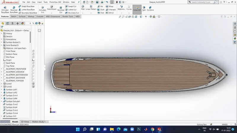
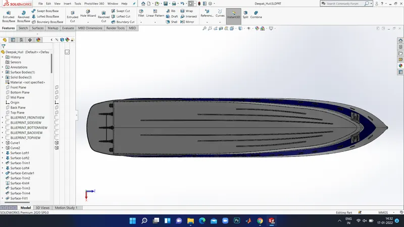
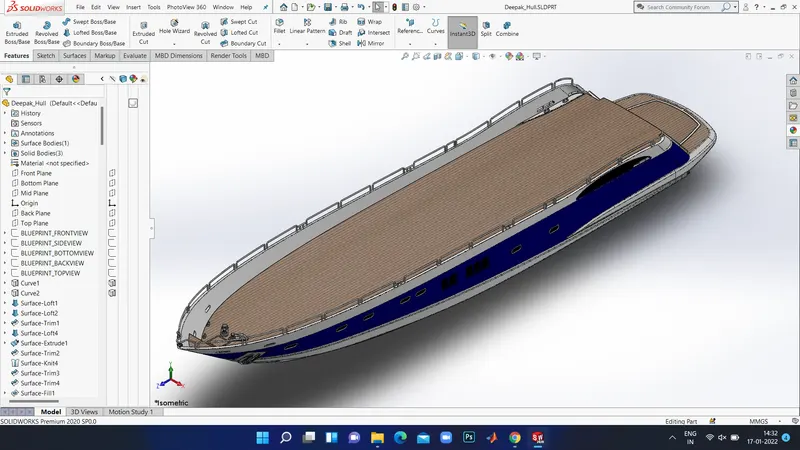
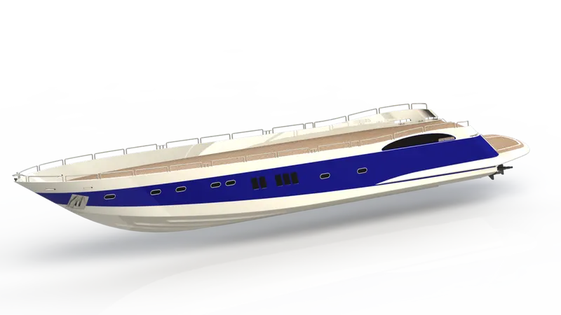
A hull is the waterlight body of a ship or boat . The hull may open at the top are it may be wholly or partially covered with a deck.... The line where the hull meets the water surfaaaaace is called the waterline .
The hull of a ship is the ,ost notble structural entity of the ship. To defined the hull it can be set htat it is the water light enclosure of the ship, which protects the cargo, machienary, and accommadation spaces of the ship from the weather, flooding and structural damage.
COMMANDS USED TO MODEL:
In Sketch
- Line
- Spline
- Circle
- Rectangle
- Arc
- Slot
- 3D Sketch
- Sketch Picture
In Surfaces
- Extrded Surface
- Revolved Surface
- Lofted Surface
- Surface Trim
- Surface Fill
- Surface Knit
- Delete Face
In Features
- Project Curve
- Chamfer
- Filets
- Reference Plane
- Split
- Split line
- Extruded Boss Base
- Extruded Cut
- Mirror
MODELLING PROCEDURE:
- The first step for modelling the yacht was creating a blueprint of it.
- the blue print was placed onnthe required planes, by using blue prints first the hull was designed.
- To create the shape of the hull , projected curves are produced by drawing the required sketch usinf splines with the help of blueprint.
- Then the projected curves were lofted to create a lofted surface and the remaining unwanted surface was trimmed using surface trim option.
- Then the back portion of the skull were the propeller needs to be placed was extruded using Extruded Surface and all the surface created must be knitted together to remove the gaps between the surfaces.
- Then the offset option is used and another surface was created and each surface was filled using surface was created and each surface fill to create the outer shell of the hull which will be converted into a solid body using knit surface option.
- Shell feature is used and another surface was created and each surface was filled using surface fill to create the outer shell of tje hull which will be converted into a solid body using knit surface option.
- Shell feature is used to create shell in the front portion of the hull.
- Then the dek surface is created using Extruded option.
- Then the required chamfers and fillets were created as shown in the pdf.
- All the windows and Portholes were designed using Extruded Cut. Then Fillets were added around the edges.
- For creating the round edges around the berth windiow, the reference planes were created and a circle ofr required dimensilns were make pierced and then swept around theedge of the windows to make them round.
- The Rails at the bottom of the yacht were created using Extruded Boss/Base and the chamfers were applied bothe the sides.
- The Cable Rollers were created using Extruded Boss/Base and the head part of it was created using Revilved Boss/Base and Extryded Cut was used to cut through the extrude and a Dome was created over it.
- Helix/spiral sketch was created to sweep the rope around the Cable Rollers.
- By using Slot option , the Rope hangers were extruded and the dome was applied and then the Linear Pattern was used to create one more.
- The window bars were created using Extruded Boss/Base.
- The staircase was created by using extruded boss/base and the hand support bar was created using Swept Boss/Base.
- The Railings around the hull was generated with the help of blueprint and the projected curve was produced and the railing reference was swept using Swept Boss/Base.
- The Axles the propeller and the surfer were created using Revolved Boss/Base optionnand using the 3d sketch.
- The anchors are created by sketching the first half and extruded with the use of Extruded Boss/Base and the other half was mirrored/
- Finally , the Garage Portion was created by using Extruded Cut and the portion was saved for later use by using split option.
- With the use of split line option, the Painting portion for our hull was split separeately.
- Then the other half of the Hull and the Axle of the surfer and propeller was mirrored to generate the complete hull using Mirror tool.
- And the part was saved by adding aproper appearances and fillets.
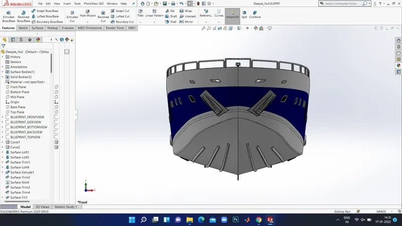
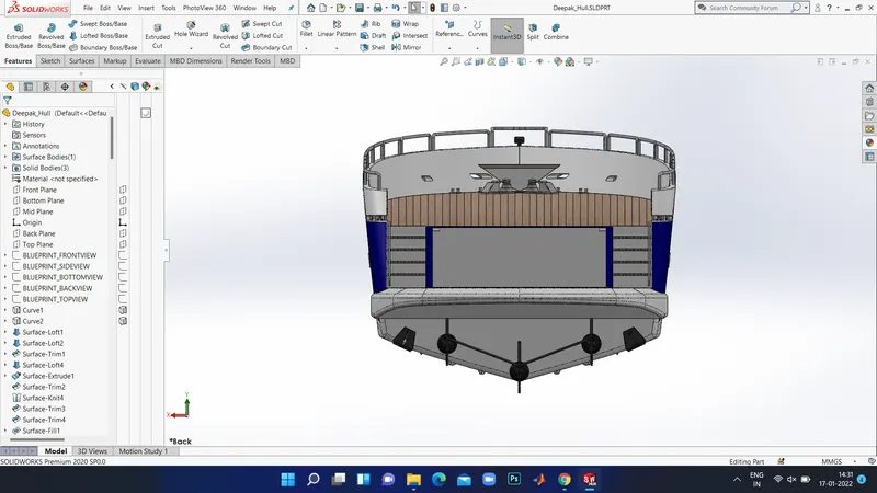
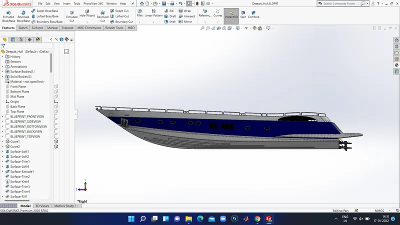
Rendered Image:
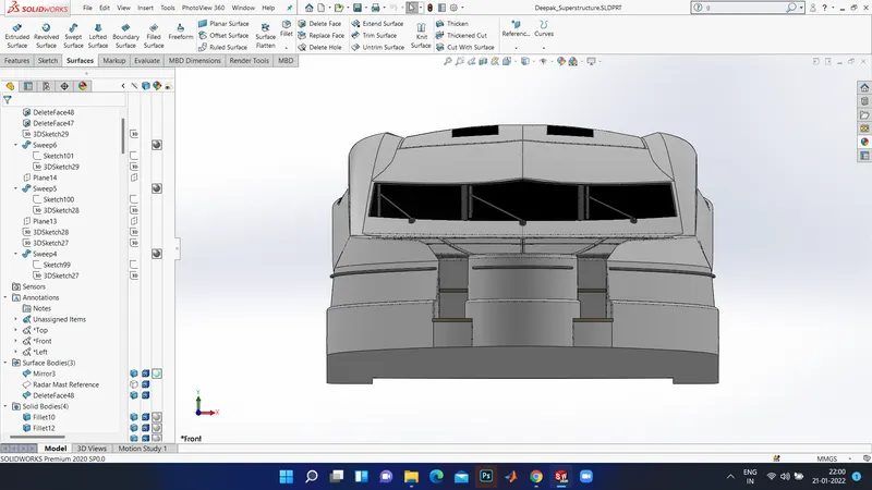
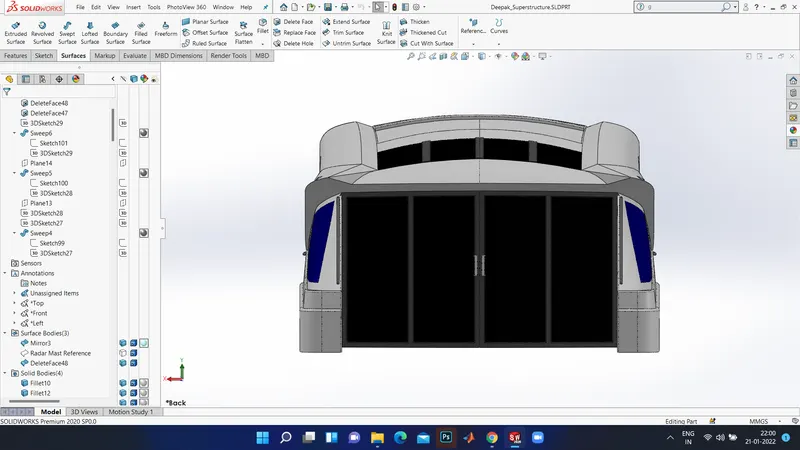
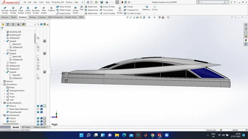
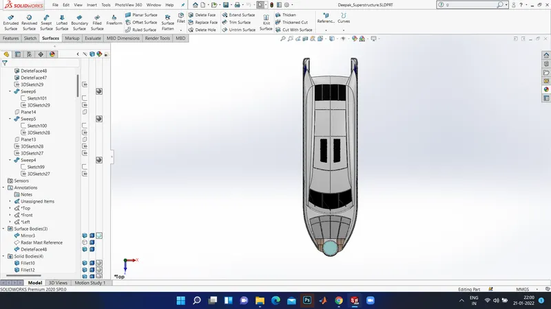
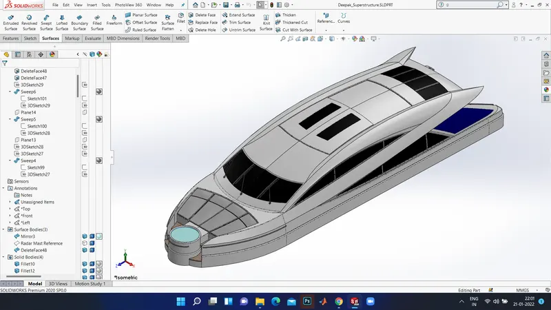
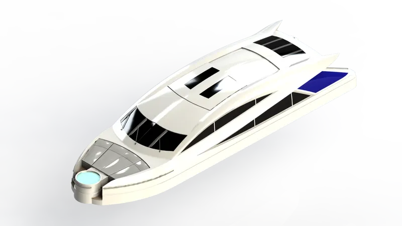
2. SUPER STRUCTURE:
A superstructure is an upward extension of an existing structure above a baseline called ground level and it usually serves the prupose of the structure's intended use. A superstructure is decked structure on the freeboard deck expanding from side to side of the ship.
COMMANDS USED TO MODEL:
In Sketch
- Sketch Picture
- 3D Sketch
- Line
- Spline
- Circle
- Rectangle
- Centre Point Arc
In Surfaces
- Extruded Surface
- Swept Surface
- Ruled Surface
- Knit Surface
- Trim Surface
- Extend surface
- Filled Surface
- Lofted Surface
- Revilved Surface
- Fillet
- Chamfer
In Features
- Project Curve
- Reference Curve
- Convert Entities
- Split
- Split Line
MODELLING PROCEDURE:
- The deck suface from the hull was imported and the superstructure was modelled over it.
- The side surface of the Superstructure is created using Extruded Surface, Lofted surface, Filled Surface, Trom Surface and Knit Surface.
- The Front side of the Superstructure was designed to have four rest beds which were created using Extruded Boss/ Base, Fillets and Dome.
- The front edge of the Superstructure was provided with a Water Feature which was formed using Exruded Boss/ Base, Extuded Cut, and filled with water appearance .
- The Windshield was created by Extrded Cut and the wipers were created by using 3 D sketch and reference plane was created using Swept Boss/ Base.
- The Portholes for the Superstructure are formed by using Extruded Surface, Trim Surface and Extended Surface.
- The left-out edges were filled using the ruled surface.
- The Back Doors fo the Superstructure was formed using Extruded Cut, Fillets and Referece Plane.
- After all the surfaces generated were Knitted together to form a solid body.
- The Superstructure consist of two surface bodies and five solid bodies.
- One of the surfaces was the Deck Surface the other one was used to place the Radar Mast so it was renaed as Radar Mast reference Surface.
- Then the other half was mirrored and the proper fillets and appearance was added and lastly the part was saved.
Rendered Image:
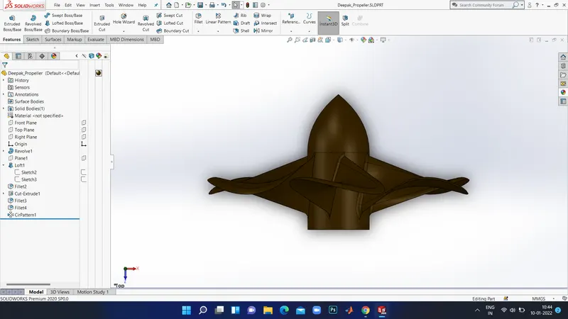
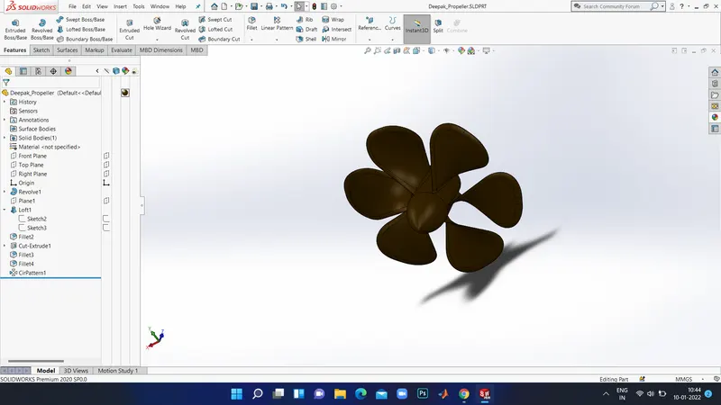
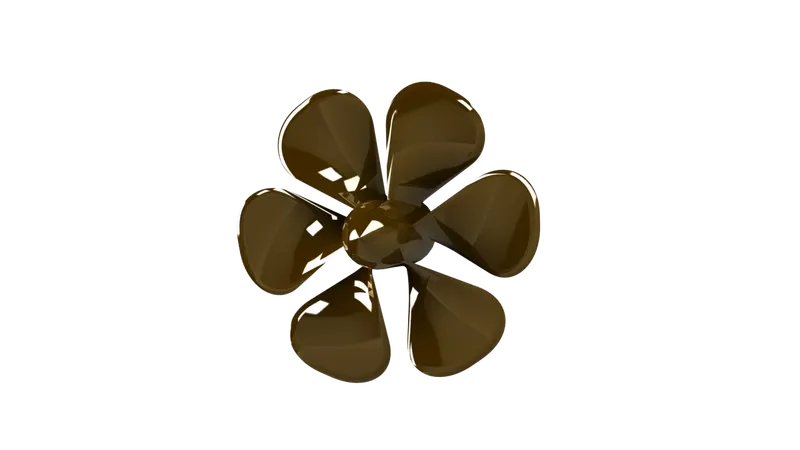
3. PROPELLER:
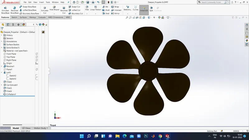
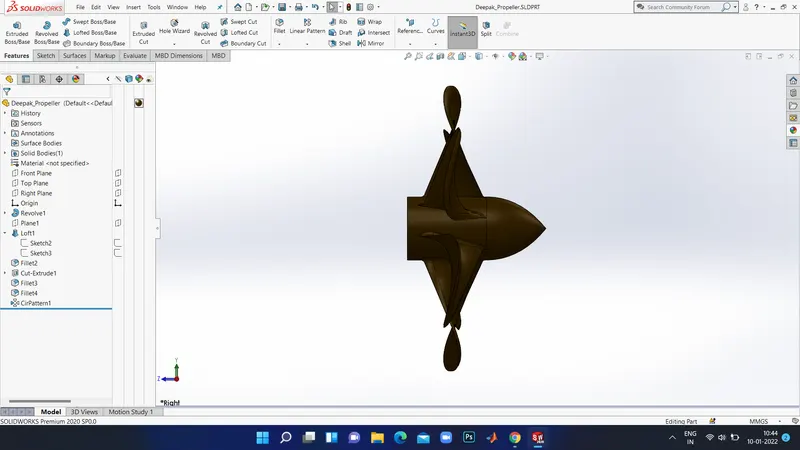
There can be one, two or three propellers. It is the most important part of the ship without which a ship can't move. So, the main function of propeller is to propel the ship in the forward direction by producing thrust on water. Its working pronciples are Newton's third law of motion and Bernoulli's theorem.
COMMANDS USED TO MODEL:
In Sketch
- Spline
- Circle
- Line
In Features
- Revolved Boss/Base
- Lofted Boss/Base
- Extruded Cut
- Refefence Plane
- Circular Pattern
- Fillet
MODELLING PROCEDURE:
- The centre portion of the Propeller was sketched and revolved using Revilved Boss/Base.
- Then the Blades were created using the Reference Plane, Lofted Boss/ b=Base and Fillet.
- The the remaining five blades were created by using Circular Pattern.
- Then the centre circular portion was removed using Extruded Cut iption. Finally, the part was saved by adding the proper appearance.
Rendered Image:
4. GARAGE DOOR:
A garage dooe is alrge door on a garage that opens either manually or by an electric motor ( a garage door opener). Garage doors are generally large enough to accommodate automobiles and other vehicles. The operating mechanism is spring-loaded or counterbalanced to offset the weight of the door and reduce human or motor effort essential to operate the door. Seldomly, some garage doors slide or swing horizontally. Doors arre made of wood, metal, or fiberglass, and may be insulated to prevent loss of heat.
COMMANDS USED TO MODEL:
In Sketch
- Line
- Spline
- Circle
- Text
In Features
- Extruded Cut
- Reference Plane
- Fillet
- Shell
- Mirror
MODELLING PROCEDURE:
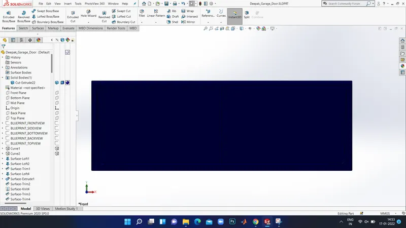
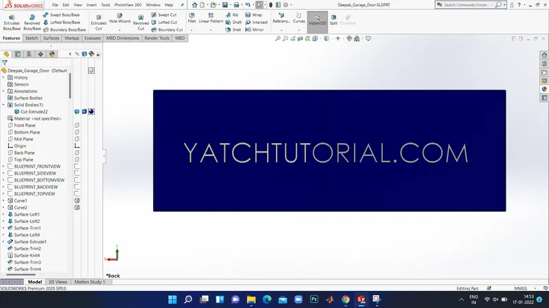
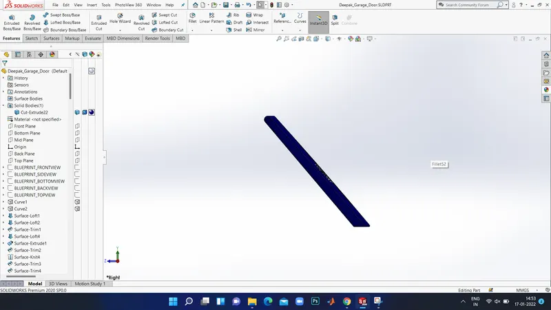
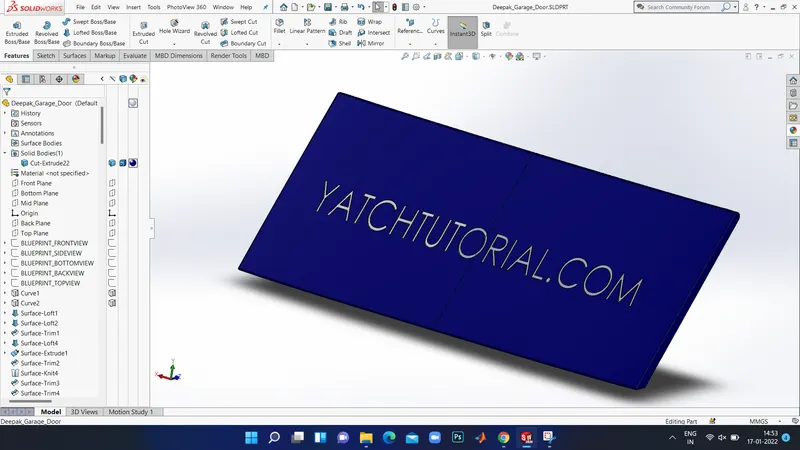
- The solid body split while manufacturing the Hull was imported to model the Garage Door.
- By using the Extruded Cut the Chamfered face for the door was produced.
- Then by using the shell feature the solid body for our garage door was formed and proper fillets were applied. After the door holders on both sides were created using Extruded Cut.
- Then the other half of the Garage Door was placed using Mirror tool after applying the required fillets.
- Then the text over the garage door " HAKUNA MATATA" was created using the tect option in sketch feature.
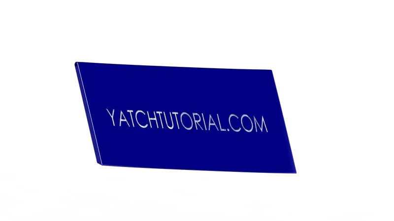
- Atlast, the part was saved by applying proper appearance.
Rendered Image:
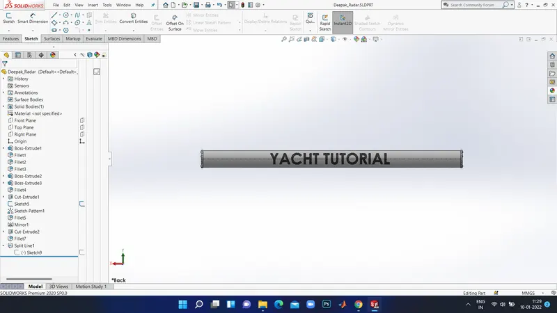
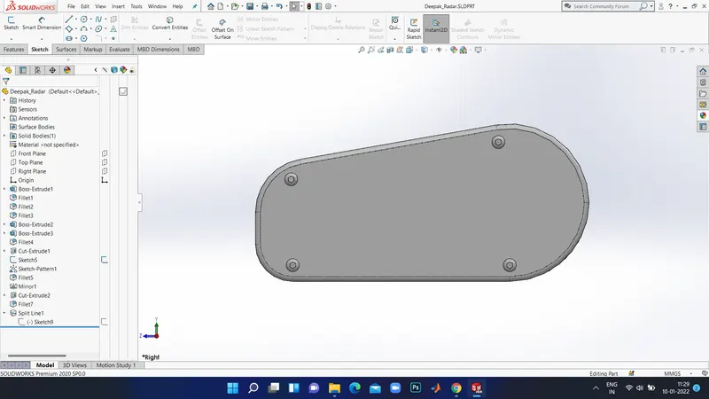
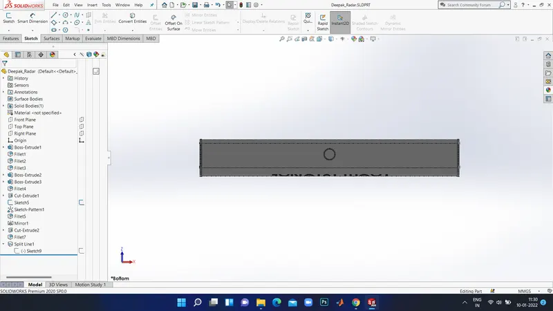
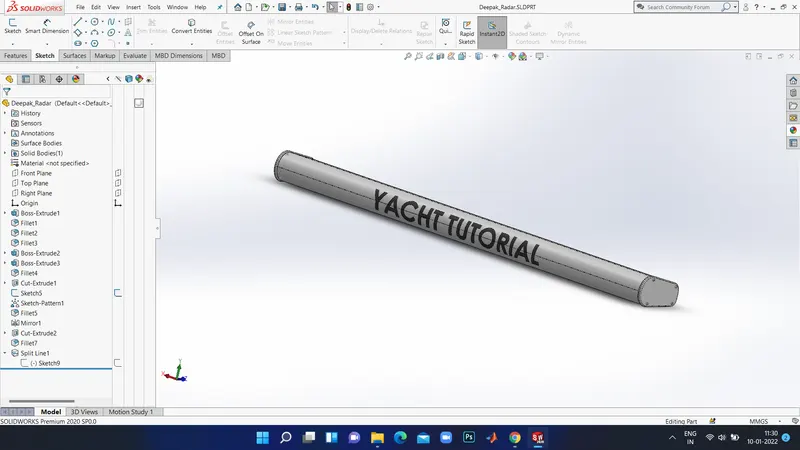
5. RADAR:
Marine radars are X band or S band dradars on ships, used to detect other land obstacles and ships, to provide bearing and distance for collision avoidance and navigation at sea. They are electronic navigation instruments that use a rotating antenna to aweep a narow beam of microwaves around the water surface surrounding the ship to the horizon , detecting targets by microwavws reflected from them , generating an image of the ship's surroundings on a display screen,
COMMANDS USED TO MODEL:
In Sketch
- Line
- Text
- Circle
- Point
In Features
- Extruded Boss/ Base
- Extruded Cut
- Sketch Pattern
- Fillet
- Mirror Split Line
MODELLING PROCEDURE:
- By drawing the required sketch, the body of the Radar was created using Extruded Boss/ Base.
- By using the Sketch Pattern, the four Dotted holes were created using Extruded Boss/ Base and Extruded Cut.
- The Radar has acircular slot undermeath which was created using the Extruded Cut .
- The other half was mirrored with the help of miror tool. The text over the Radar was created using the Text option in sketch and then the Split Line was used to produce over the face of the radar.
- At last , the radar must be filleted around the edges of the body and also around the four holes.
- Finally, the part was saved by adding proper appearance.
Rendered Image:
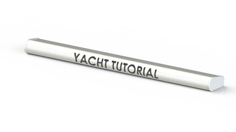
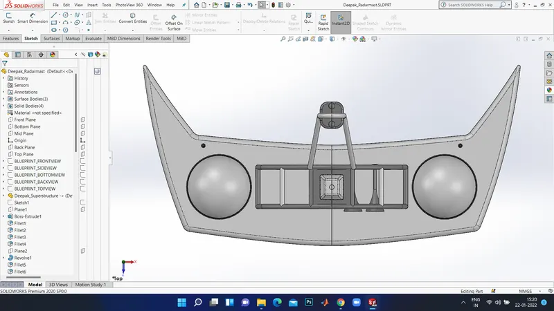
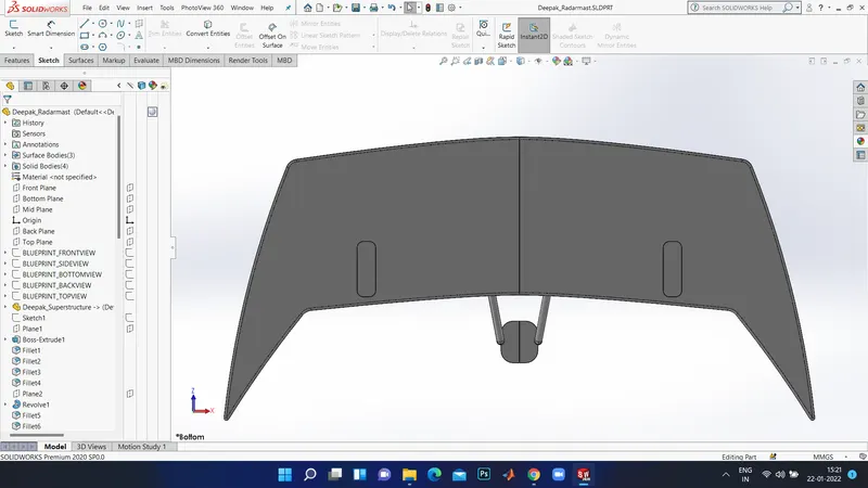
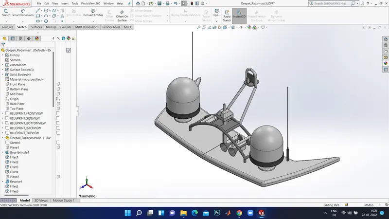
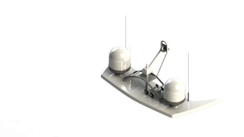
6. RADAR MAST:
A mast is a vertical ship structure mounted on top of bridge and forward of the forecastle towards the ship's bow. It accounts for the support platform for th eships derrick and hold mandatory equipment's such as radars, navigation light and ships horn in case of foremast. They are made up of high tensile steel with added rigidity depending on the size of derricks it holds. Other than that , a ship main mast is also used in hoisting ships flag.
Out of various parts of ship hte chief hob of mast is to hold necessary equipment such as radar recerver, navigtion lights, ships horn, flags and derricks in some case.
COMMANDS USED TO MODEL:
In Sketch
- Sketch picture
- Line
- Spline
- Rectangle
- Arcs
In Features
- Extruded Boss/ Base
- Lofted Boss/ Base
- Revolved Boss/ Base
- Swept Boss/ Base
- Reference Plane
- Projected Curve
- Fillet
- Mirror
- Dome
- Shell
MODELLING PROCEDURE
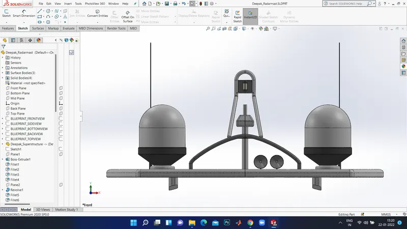
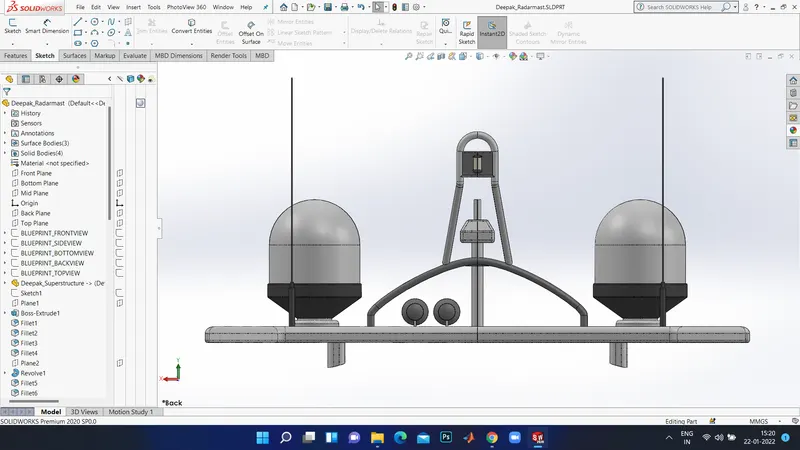
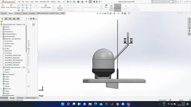
- The first half of the Radar was Modelled with the help of blueprint and then the second half was mirrored with the help of Mirror tool.
- The body of the Radar was created with Extruded Boss/Base and Revolved Boss/ Base
- The antenna of the radar was also created using the Extruded Boss/Base.
- The lamp stand along with the connnecting rod were designed using the Swept Boss/ Base and Mirror tool. The lamp was created using the projected curve and then the curve was swept using swept Boss/Base.
- The horns were designed using the Revolved Boss/Base, Dome and Shell.
- After the fillets and chamfers were applied wherever necessary.
- In the end , the part was saved by applying appropriate appearances.
Rendered Image:
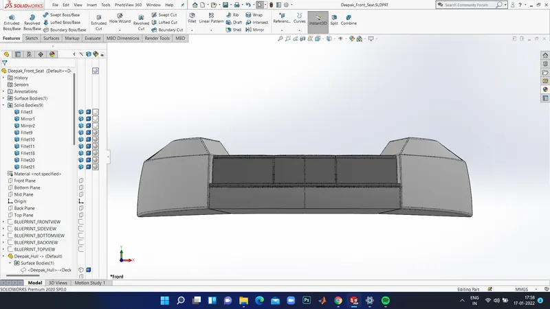
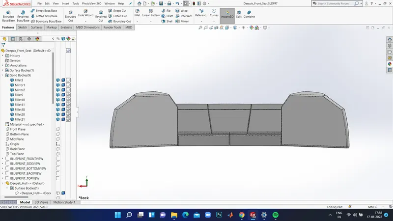
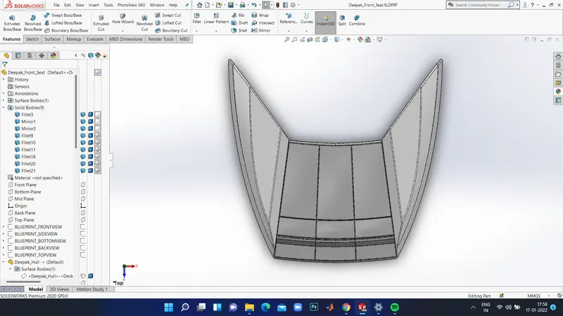
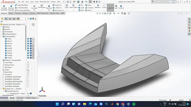
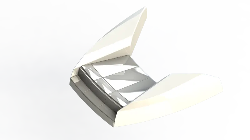
7. FRONT SEAT :
Front seats feature two connected seats that are built back-to- back from one and the other. They have a built- in storage unit underneath them . Lounge seats can also fully recline right back to make it easier for you to kick your feet up and get more cosy. The front seat in our model was placed before the superstructure and also it has sun pads to lean on it. Sun pads are a great way to reclaim lost space on our boat.
COMMANDS USED TO MODEL:
In Sketch
- Sketch picture
- Line
- Spline
- Circle
- Arcs
- In Surfaces
- Extruded Surface
- Lofted Surface
- Trim Surface
- Filled Surface
- Knit Surface
- Swept Surface
- Revolved Surface
In Features
- Extruded Cut
- Revolved Boss/Base
- Chamfer
- Fillet
- Mirror
- Dome
MODELLING PROCEDURE:
- The Front seat of the Yacht was also created using Blueprint.
- The first half was modelled and the next hald=f was mirrored using Mirror tool.
- Next the front seat was placed before the Superstructure facing the Water Feature of the Superstructure and the back end must be placed on the bow of theYacht/
- The body of theFront Seat was modelled using Swept Surface , Extruded Surface, Filled Surface, Lofted Surface and the unnecessary part was remoged using Trim Surface.
- Later the four Rest Beds aere created uning Extuded BossBase and the dome was created over the face of the beds seperately.
- Then the required fillets and chamfers were created with the extruded thin surfaces.
- Finally , the part was saved by adding proper appearances.
Rendered Image:
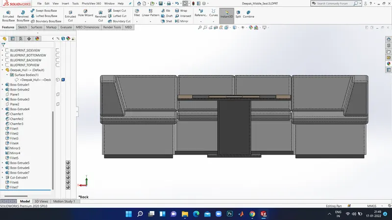
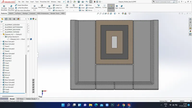
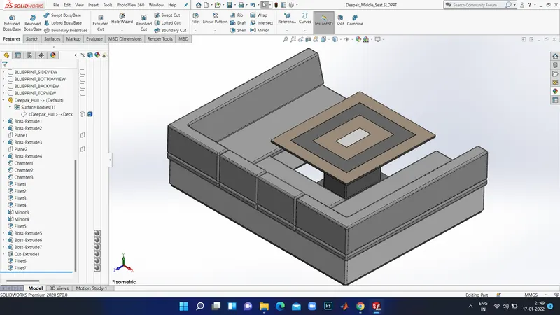
8. MIDDLE SEAT:
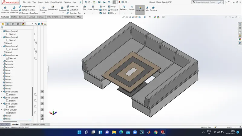
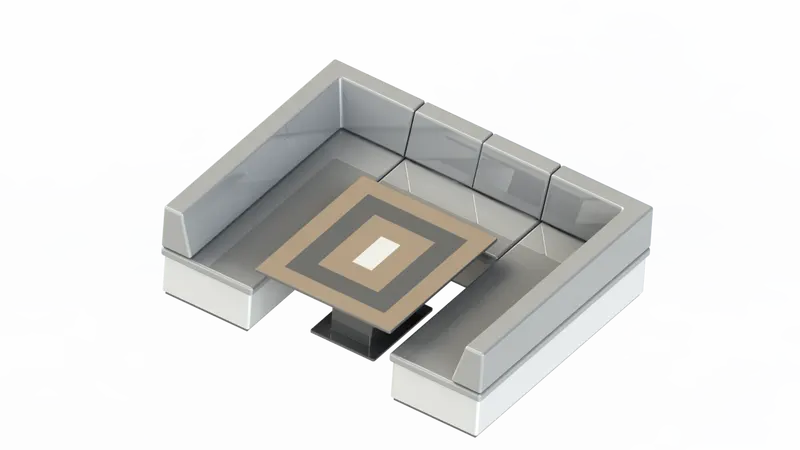
The middle seat in our model was adjusted just behind the wuperstructure. It is provided with a luxury table for dining . It can also be used to have casual conversations with co-passengers.
COMMANDS USED TO MODEL:
In Sketch
- Sketch Picture
- Line
- Rectangle
In Features
- Extruded Boss/ Base
- Chamfer
- Fillet
- Mirror
- Reference Plane
MODELLING PROCEDURE:
- The Middle Seat was created using the Extruded boss/Base and by applying the Chamfers and fillets as wanted.
- All surfaces created must be Knitted togerher by using the option Knit Surface.
- The Dining Table was created using Reference Plane, Extruded Boss/ Base , Off-set, Chamfers and Mirror.
- Then the other half of the Middle Seat must be mirrored symmetrically.
- Atlast, the part was saved by applying the proper appearance.
Rendered Image:
9. REAR SEAT:
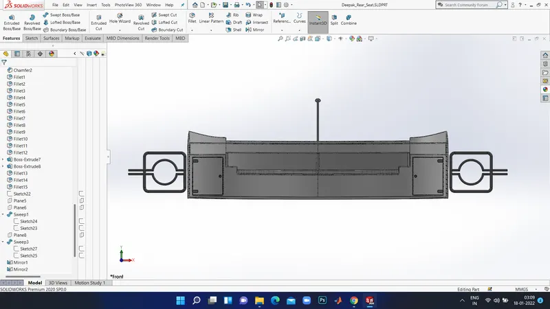
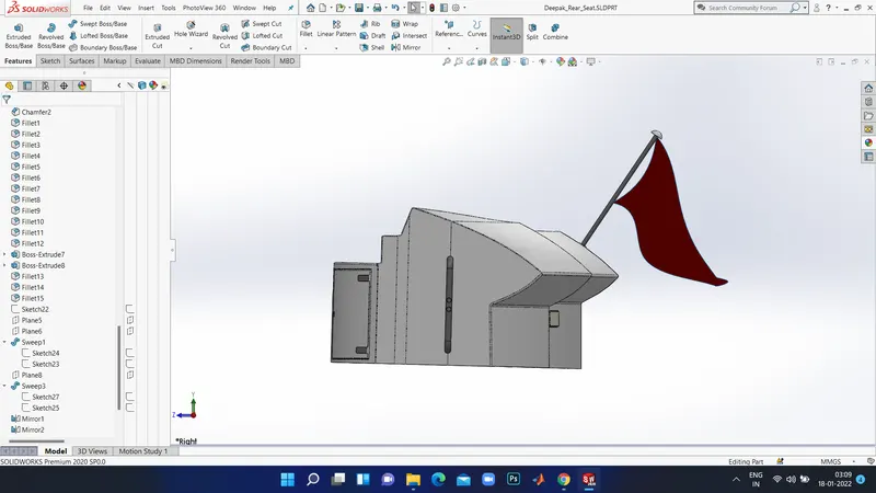
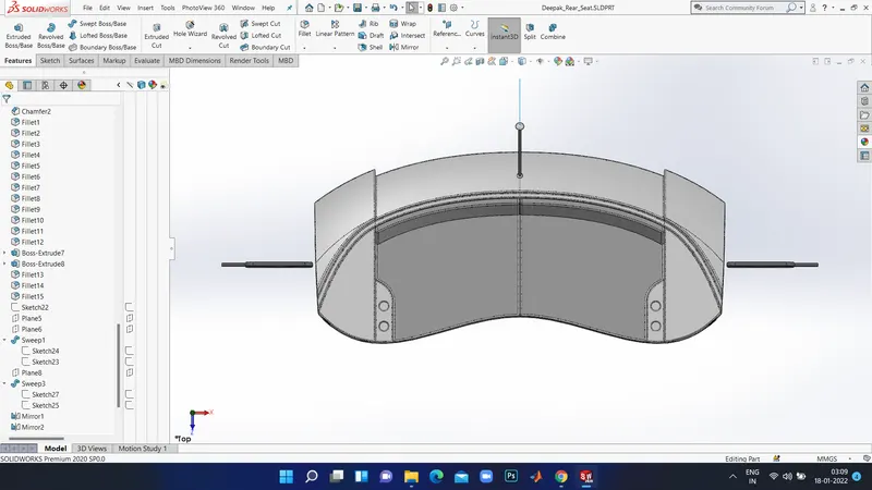
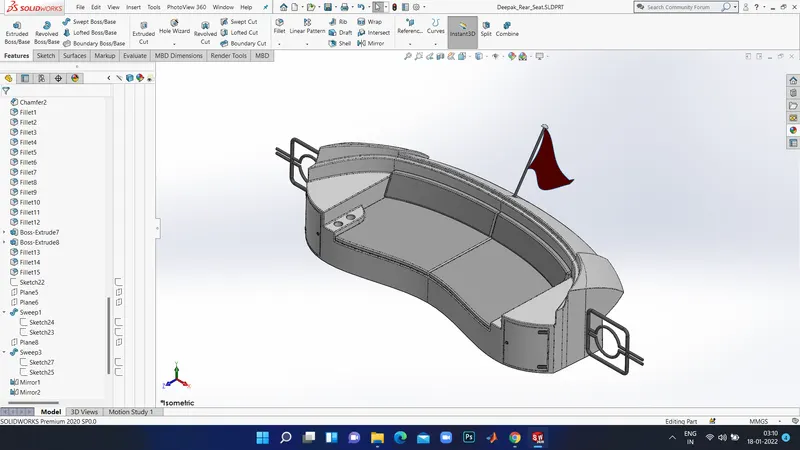
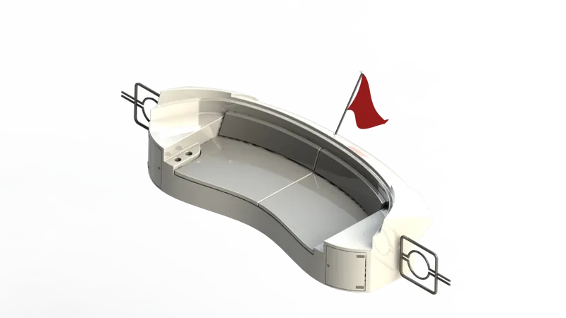
The rear seat was placed at the end of the deck surface. The rear seat consists of locker racks and steel doors for our stairs. The flag was also placed behind the rear seat as it's the end part of our yacht. To have a nice view from the yacht while having a drink the rear seat was also provided with a slot to rest the glass or mug.
COMMANDS USED TO MODEL:
In Sketch
- Sketch Picture
- Line
- Spline
- Circle
- Arcs
- Rectangle
In Surfaces
- Swept Surface
- Extruded Surface
- Off-Set Surface
- Filled Surface
- Knit Surface
- Ruled Surface
- Lofted Surface
In Features
- Reference Plane
- Extruded Boss/Base
- Revolved Boss/ Base
- Fillet
- Mirror
MODELLING PROCEDURE:
- The chief body of the Rear Seat was midelled with the help of Swept Surface, Off-Set Surface and the remaining portion was trimmed using Trim surface tool.
- By using the Reference Plane, the Seats were created with the help of surfae trim, lofted surface and Extended Surface.
- The Flag Post was created with thte help of Tevolved Boss/Base and the Flag was created by drawing the required 3 D sketch and then the 3D sketches were lofted to form the Flag.
- The Tail Lamps were created using Extruded Boss/Base , Mirror tool and fillets
- The Steel Gates for Stairs were designed by using the reference plane and the Swept Surface.
- To reomve the gaps the all the Surfaces must be Knitted together with the help of Knit Surface.
- The required fillets and chamfer were created befor mirroring the sexond half using Mirror tool and after mirroring the uncreatred areas were filleted once more. Finally, the part was saved by adding suitable appearances.
Rendered Image:
ASSEMBLY:
An assembly is a document in which features , parts , and other assemblies i.e., sub- assemblies are mated together.The parts and susassemblies existed in documents separate from the assemble. For Instance, in an assembly , a piston can be mated tomother parts,such as a connecting rod or cylinder. This new assembly cna then be utilized as sub-assembly in an assembly of an engine. the extension for a Solid Works assembly file is named as SLDASM.
ASSEMBLY COMMANDS:
- Smart mate: It is an assembly mating relation that is created automatically.
- Mate: A mate is a geometric relatioship , such as coincident, perperdicular, tangent, and jetc, between parts in an assembly.
Mate Group:
A mate group is a collection of mates that are solved together. The order in which the mates appear within the mate group is not of any significance.
Sub-Assembly:
It is an assembly document that is part of a larger assembly. For instance , the steering mechanism of a car is a subassembly of the car.
Insert Components - One can insert multiple instance s of the group of components without closing the Property Manager.
Assembly Procedure:
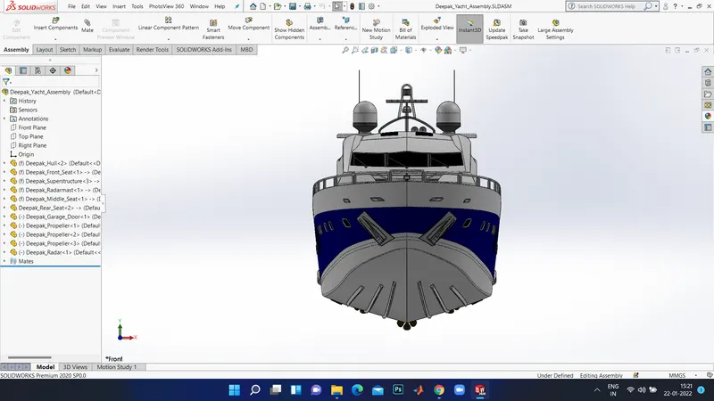
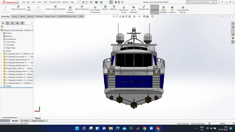
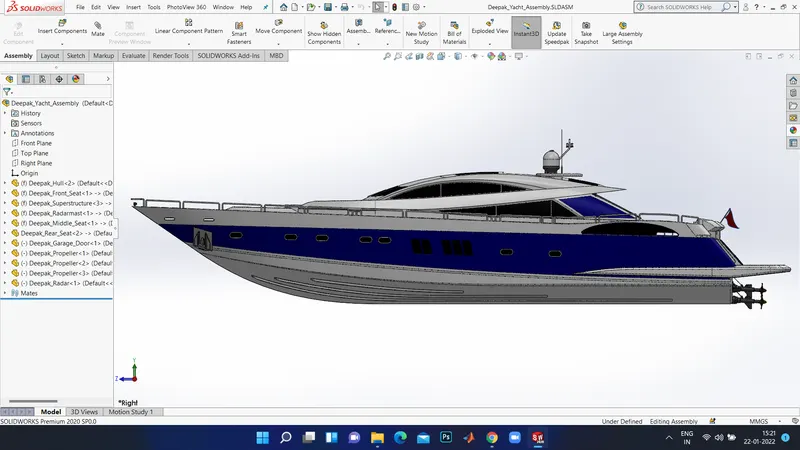
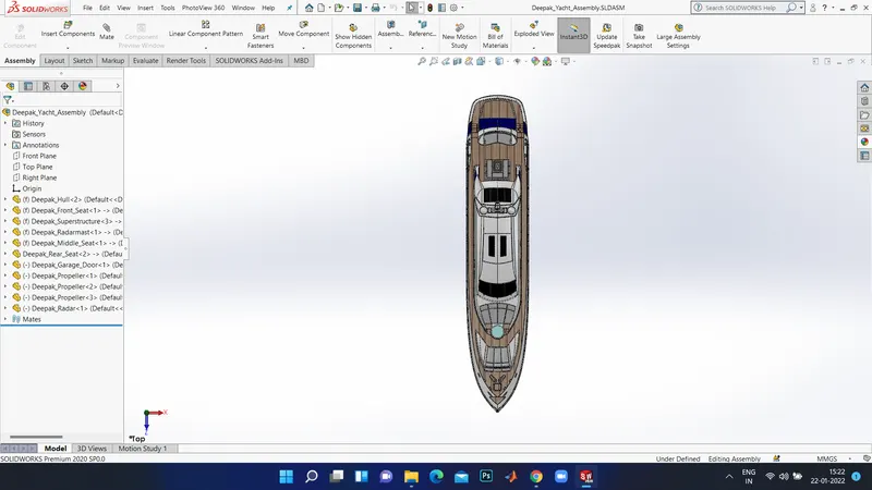
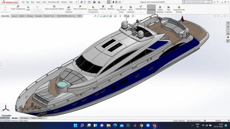
- Import all tha parts manually using the option Insert Components.
- Next fix the Hull part by applying the coincident mate to the Top, Right and Front planes of the Assembly and Hull respectively .
- Then for each part apply the necessary mates required by the Blueprint using Coincident mates, Angle Mates, Distance mats etc.
- Advanced mate was also used wherever required.
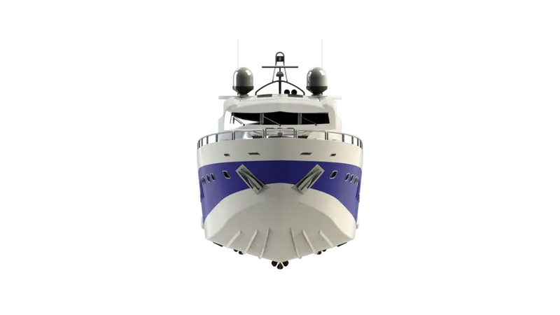
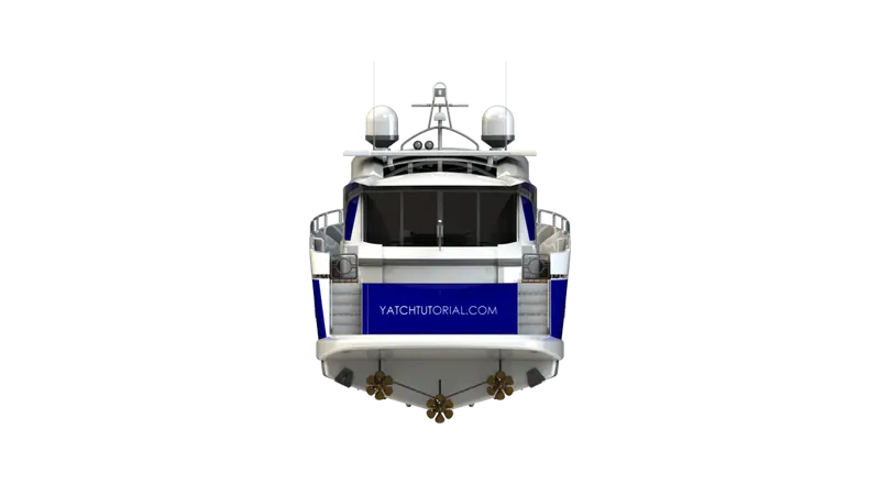
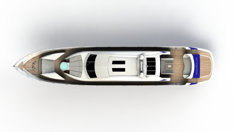
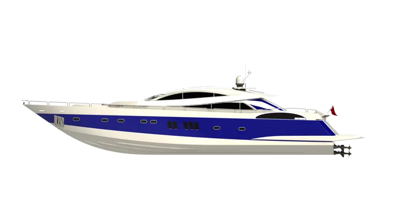
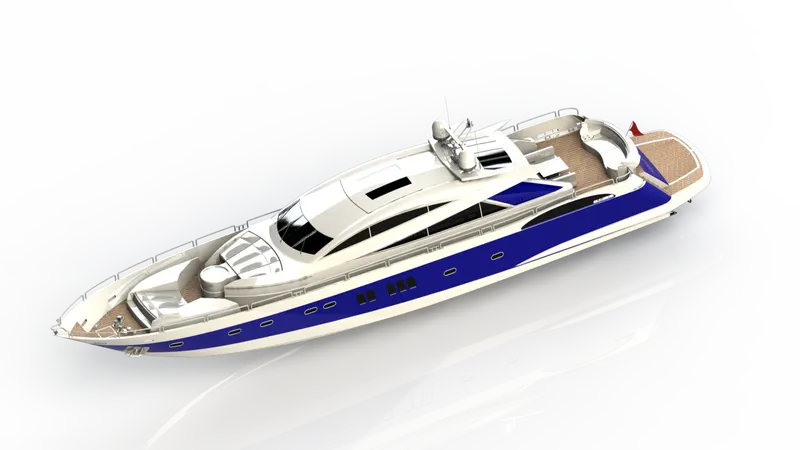
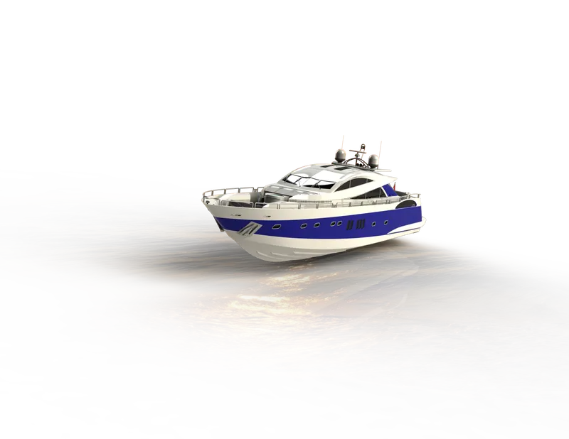
Rendered Images:
Rendering:
- Rendering is a process of creating realistic images of the photorealistic model with the environment.
- Rendering has been done in two ways in solidworks.
- Photoview 360
- Solidworks Visualize
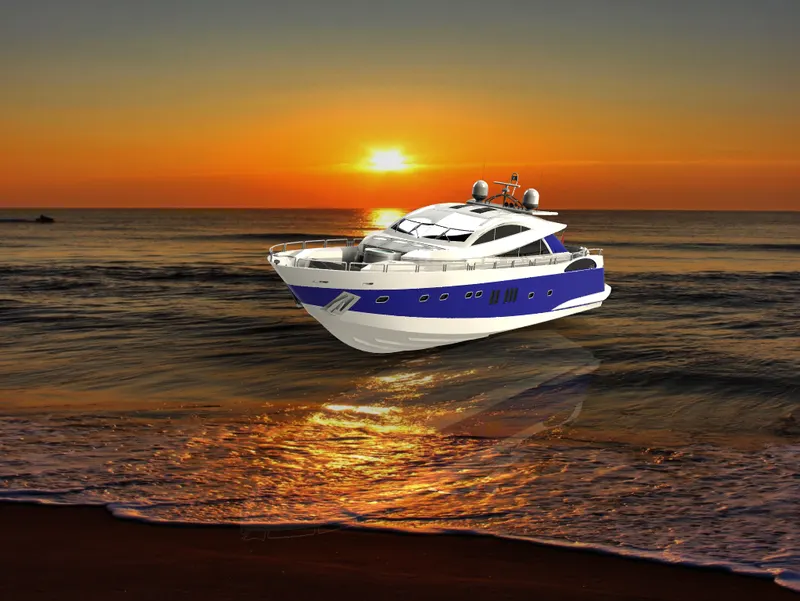
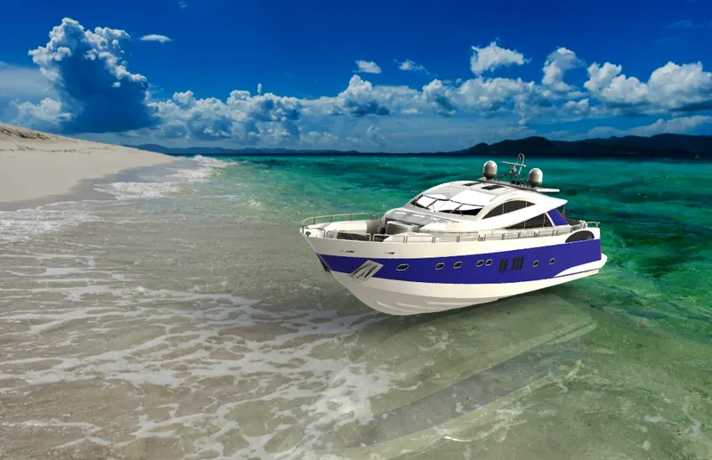
In the photorealistic model some of the mate conditions and positions are changed to render realistic models.
Then, the photorealistic model is rendered into realistic images with different views.
Photoview 360:
Photoview 360 is a visualization and rendering solution includes with solidworks.Providing a highly interactive environment for viewing designs as well as for creating Photo-realistic rendering it can be used to showcase our designs as well.
Solidworks Visualize:
Solidworks Visualize Provides a suite of stand-alone software tools that combine industry leading rendering capabilities with visual design-oriented features and workflows,allowing easy and fast creation of visual content that communicates a design vision,passion and emotions.
Conclusion:
- The parts of the Sunseeker Predator Yacht are modelled.
- The parts are inserted into the assembly environment and the Yacht is assembled.
- The realistic image was rendered with the use of the Photoview 360 and Solidworks Visualize.