Radar Mast & Final Assembly of Yacht
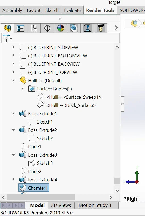
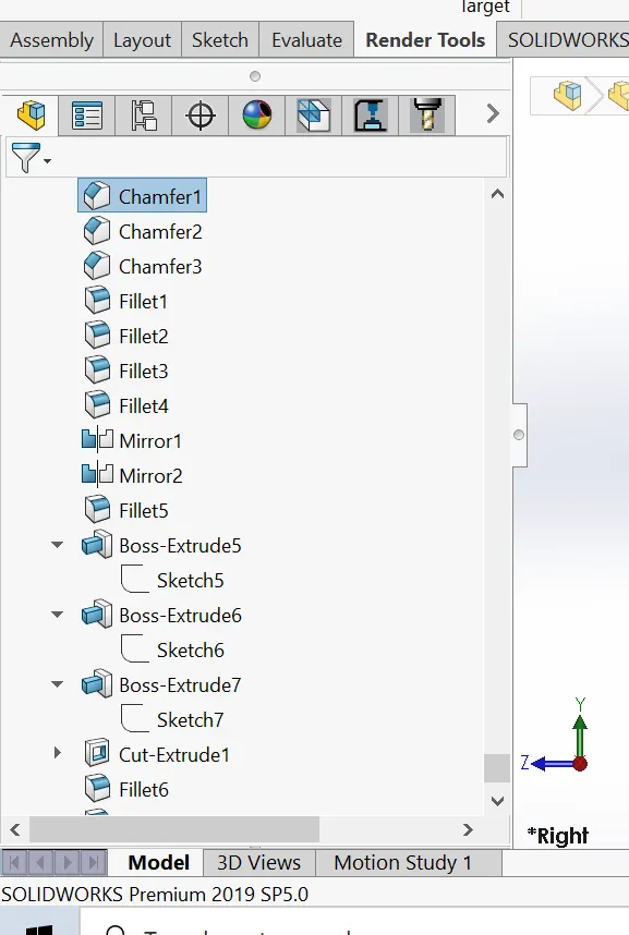
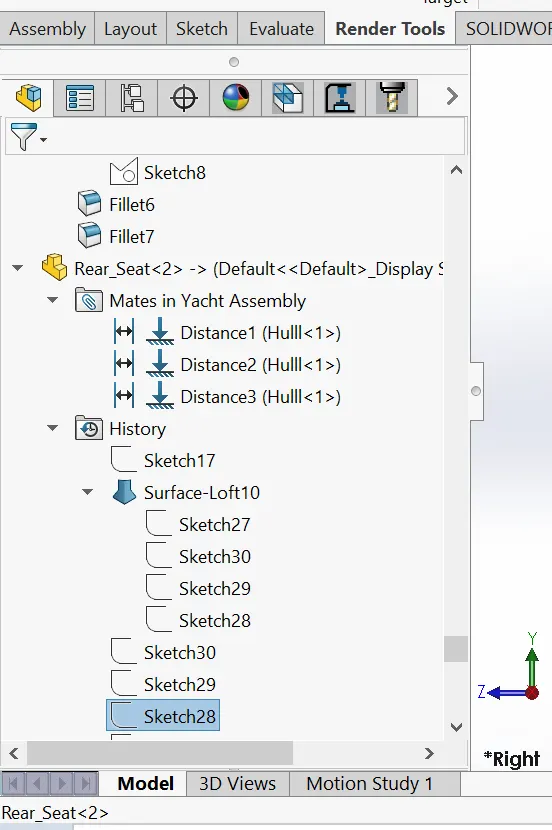
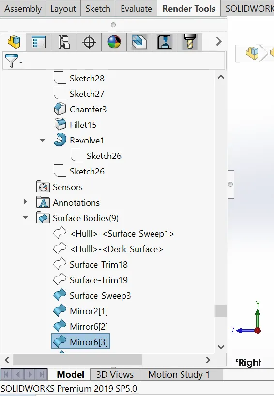
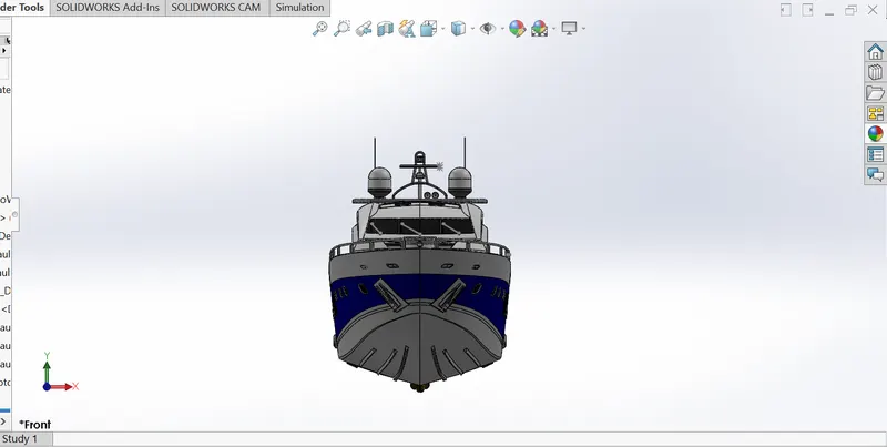
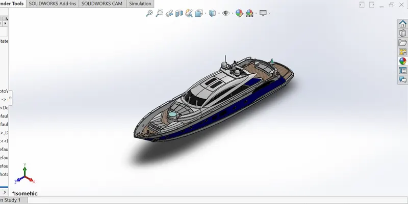
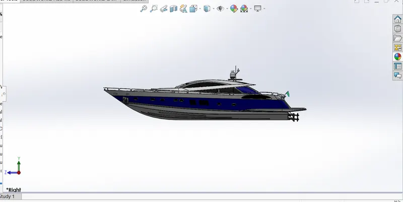
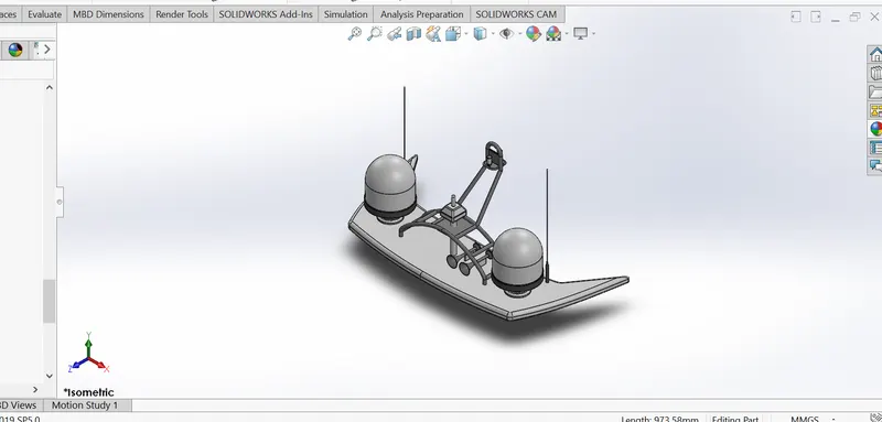
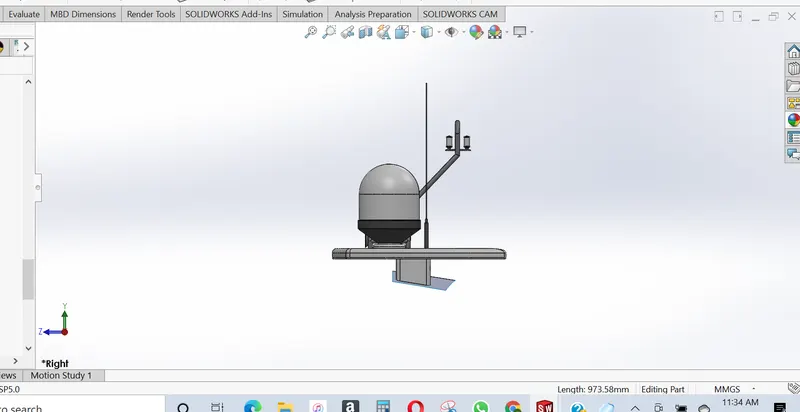
MODELLING AND RENDERING OF A YACHT WITH SOLIDWORKS
TABLE OF CONTENT
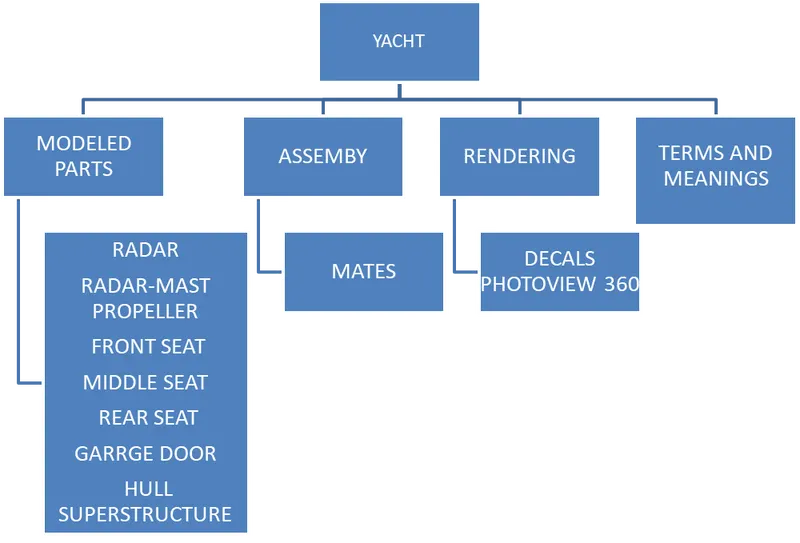
- Modeling Parts of the Yacht
- Assembling Modeled Parts of the Yacht
- Rendering (With PhotoView 360)
- Terms and Meaning
INTRODUCTION
SOLIDWORKS is used to develop mechatronics systems from beginning to end. At the initial stage, the software is used for planning, visual ideation, modeling, feasibility assessment, prototyping, and project management. The software is then used for design and building of mechanical, electrical, and software elements. Finally, the software can be used for management, including device management, analytics, data automation, and cloud services. In this project, Solidworks was used to create, edit and visualize 3D models, rendering with photo-view 360 and detailed model drawings. Solidworrks was also used to give the model the desired appearances, as well as assembling of modeled Parts of the Yacht.
MODELLING PARTS OF A YACHT
PROPELLER
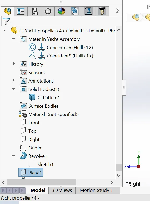
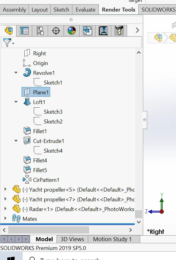
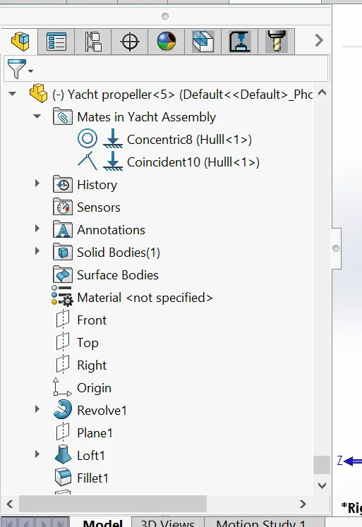
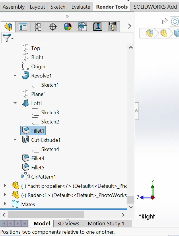
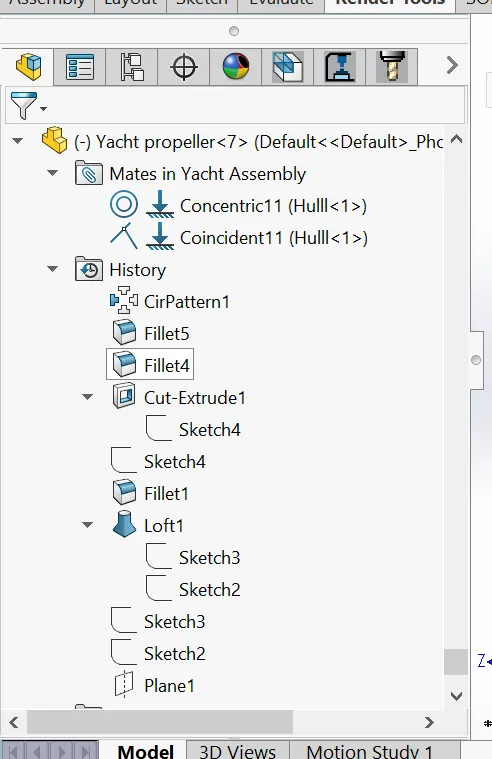
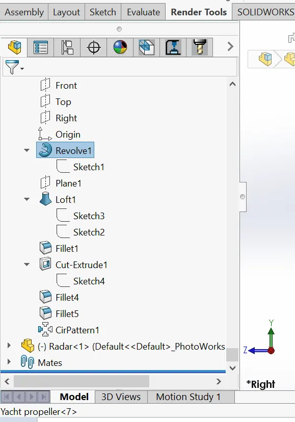
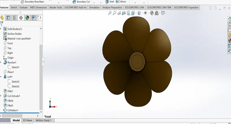
Propeller blades displace water, to create the forces that move a boat forward. The basic propeller shaft creates the torque, or energy required to turn the blades. But, the design of propeller blades is what creates the displacement of water. The displacement of water is what creates forces that move a boat forward, In Creating a Propeller using solidworks involves creating a 2D spline and circular Patterning. Below are some of the features that were used in modeling the Propeller.
- Sketch
- Cut Extrude
- Circular Pattern
- Revolve
- Loft
- Fillet
Please see terms and meaning for meaning of features
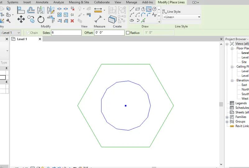
RADAR
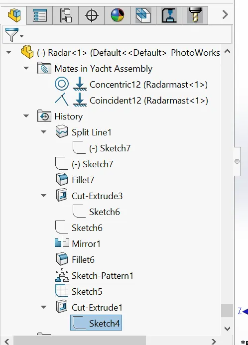
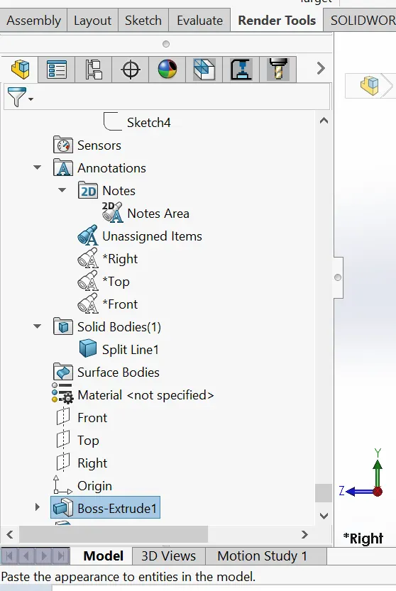
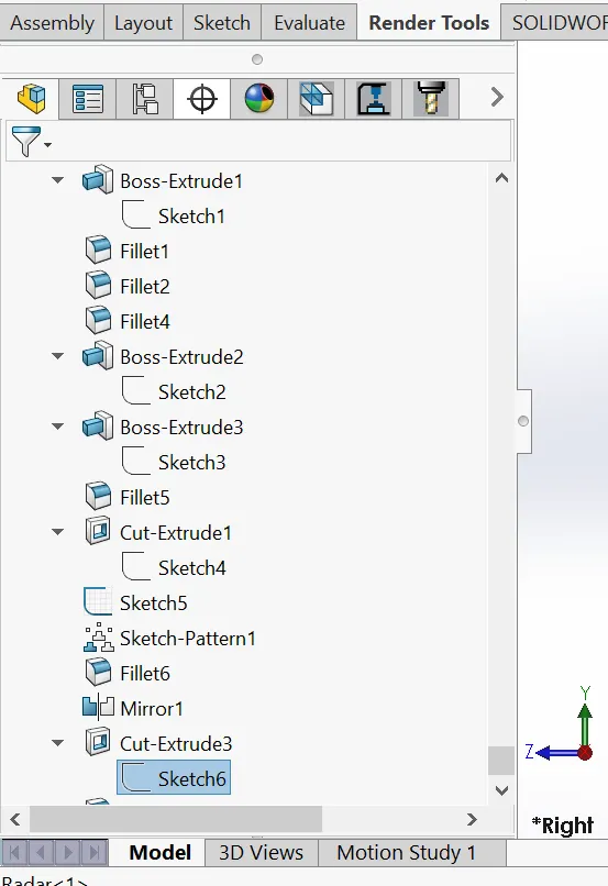
Marine Radars are the best collision avoidance system ever developed for the recreational boater. Radar systems let you “see” through darkness, fog and stormy weather conditions. Once used only on large vessels, radar units are now compact, draw little electricity and are sized to fit boats and Yacht as small as 18' in length. Creating a Radar using solidworks involves creating a 2D Sketches and mirroring. Below are some of the features that were used in modeling the Radar.
- Boss Extrude
- Cut Extrude
- Split line
- Mirror
- Fillet
Please see terms and meaning for meaning of features
RADAR-MAST
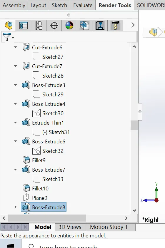
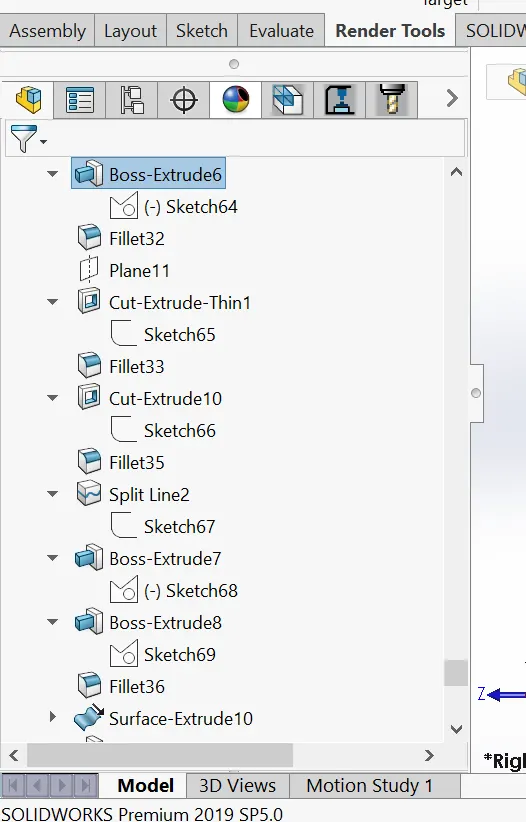
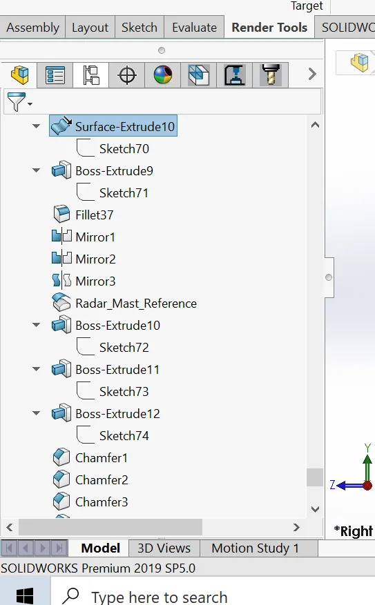
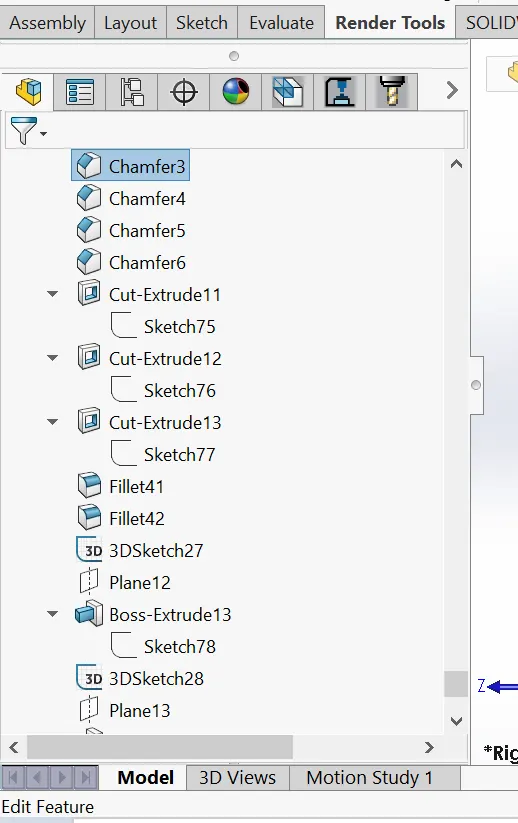
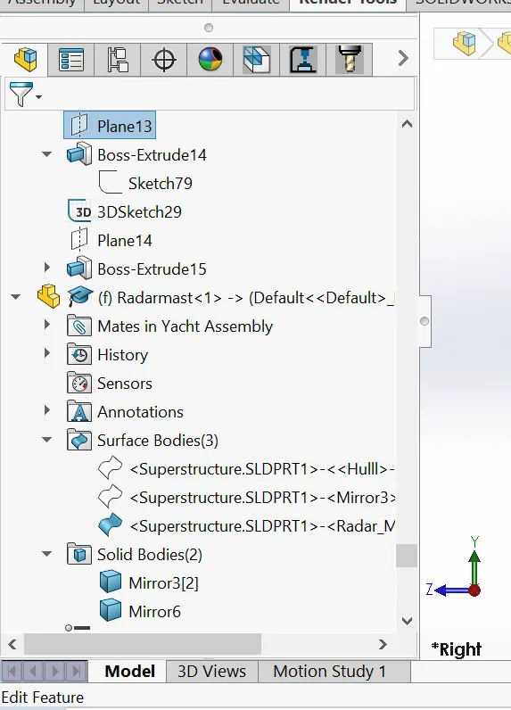
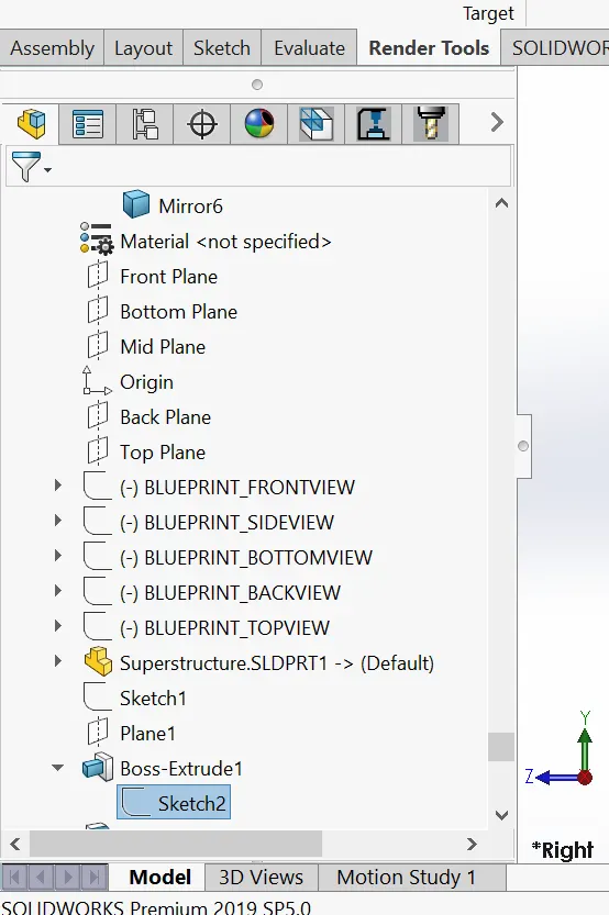
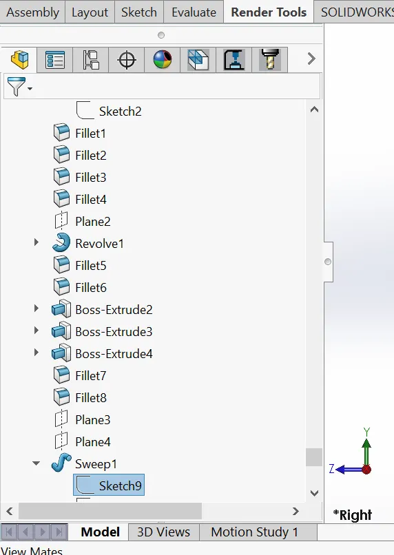
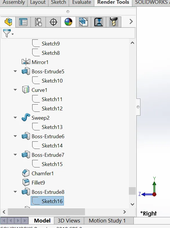
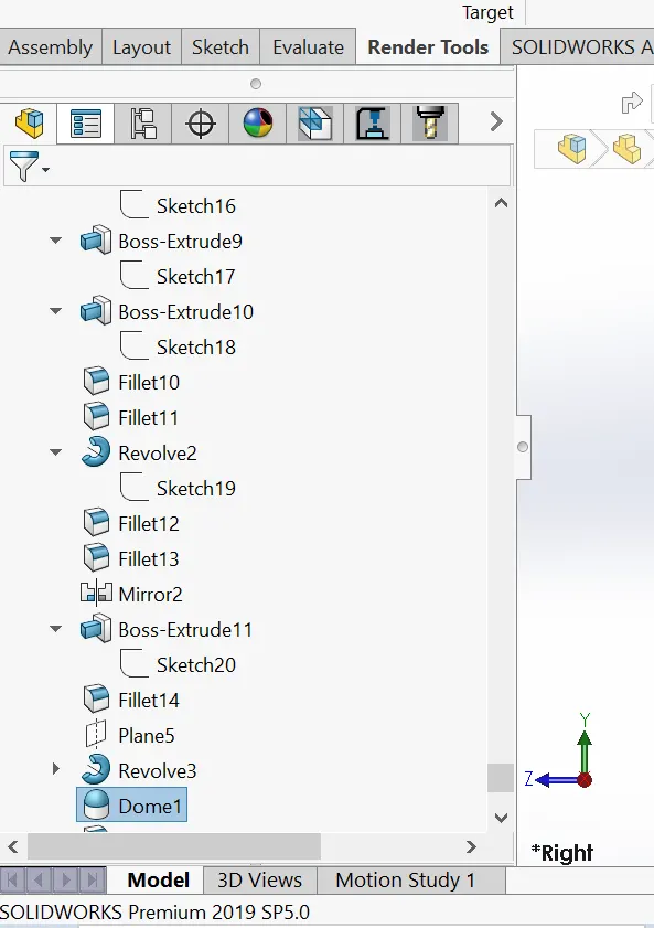
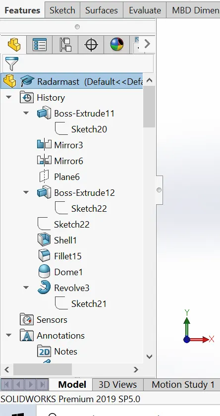
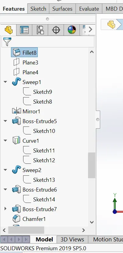
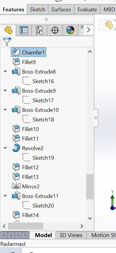
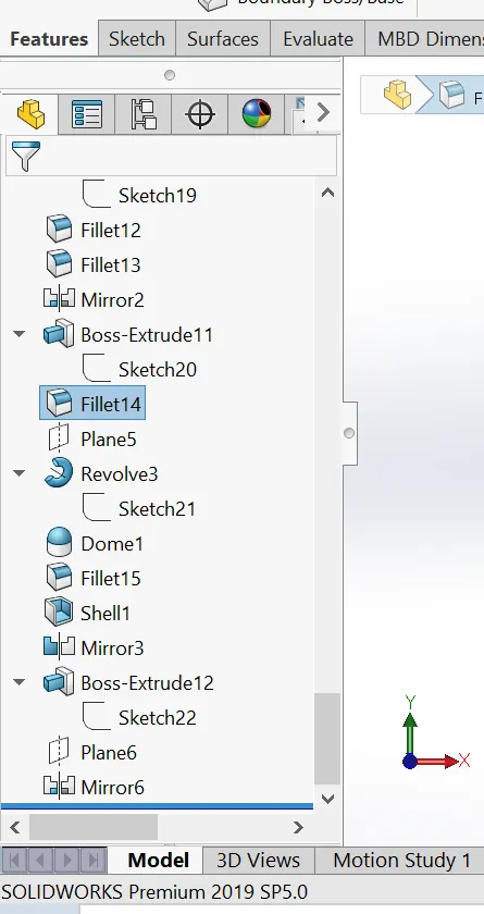
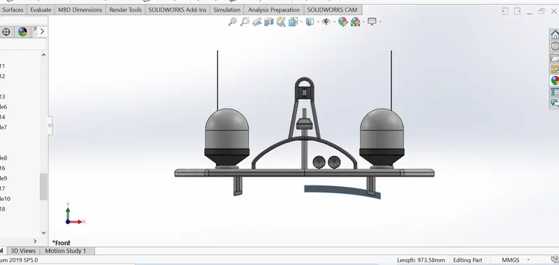
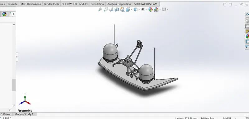
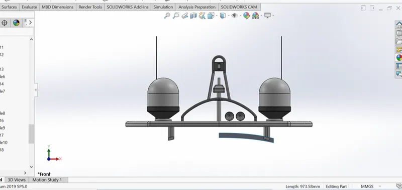
Radar mast are electronic navigation instruments, that use a rotating antenna to sweep a narrow beam of microwaves around the water surface surrounding the yacht to the horizon, detecting targets by microwaves reflected from them, generating a picture of the yacht surroundings on a display screen.; see some features that were used in the creation of this Radar mast below.
- Sketch
- Bose Extrude
- Revolve
- Projected curves
- Sweeps
- Shell
- Fillet
- Dome
- Chamfer
Please see terms and meaning for meaning of features
FRONT SEAT
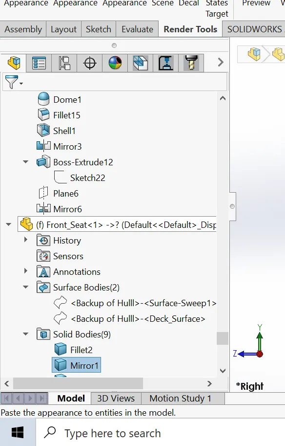
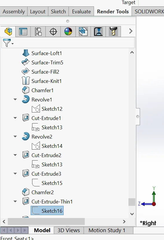
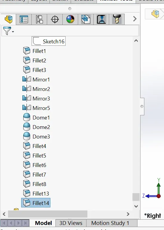
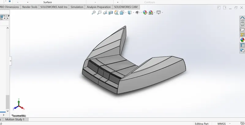
The front seats on the yacht are the seats closest to the bow of the yacht. In creating this part, I made use of spline, pierce relation etc. Below are some of the features that were used in modeling the front seats.
- Revolve
- Cut Extrude
- Chamfer
- Dome
- Fillet
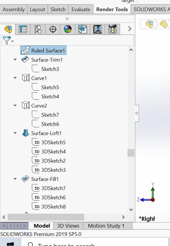
- Surface trim
- Surface fill
- Surface knit
- Surface loft
Please see terms and meaning for meaning of features
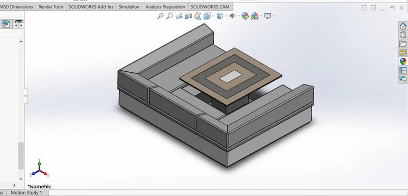
MIDDLE SEAT
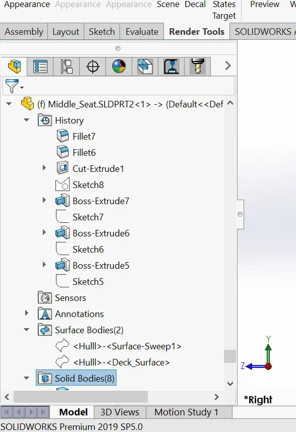
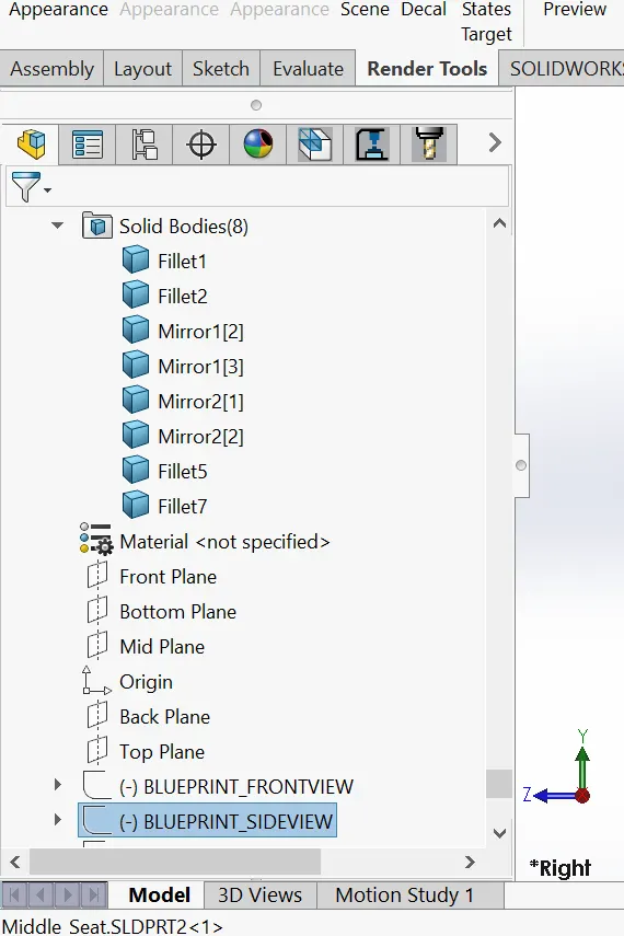
The Middle seat of the Yacht is located between the bow and the stern of the yacht. In modeling the middle I made use of boss Extrude, fillet, chamfer and some image mirroring. Below are some of the features that were used in modeling the Middle seats.
Please see terms and meaning of features
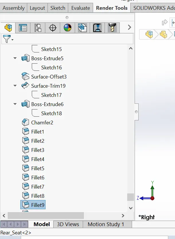
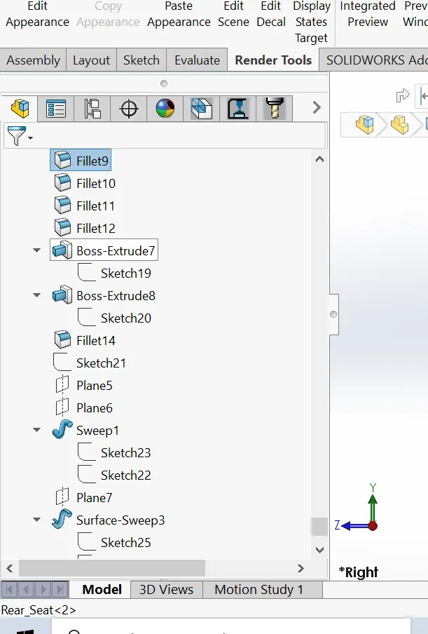
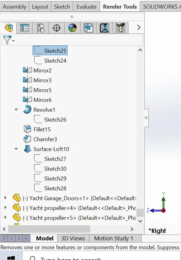
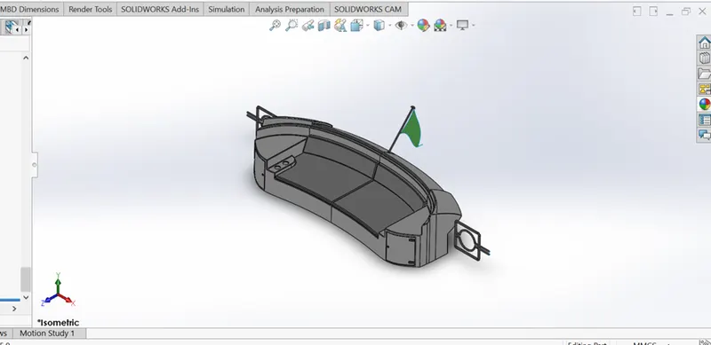
REAR SEAT
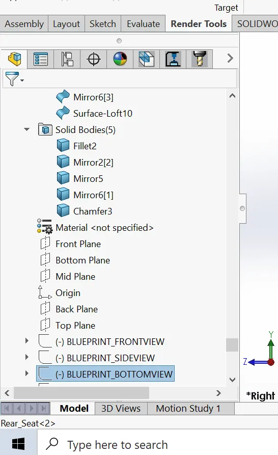
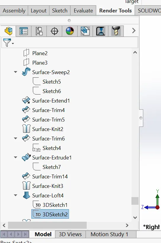
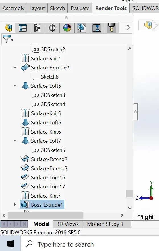
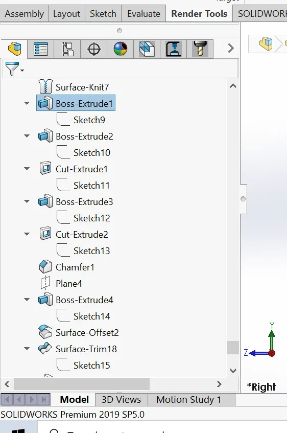
This is the seat closest to the stern of the yacht, below are some of the features that were used in modeling the rear seat.
- Sketch
- Boss Extrude
- Cut Extrude
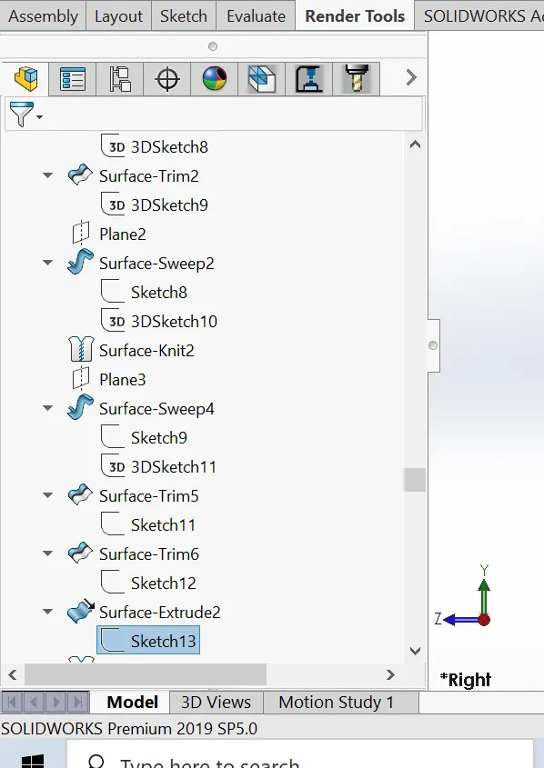
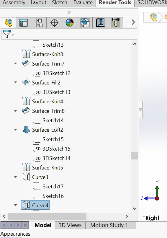
- Surface Knit
- Surface sweep
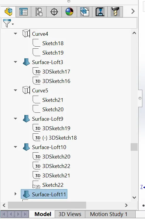
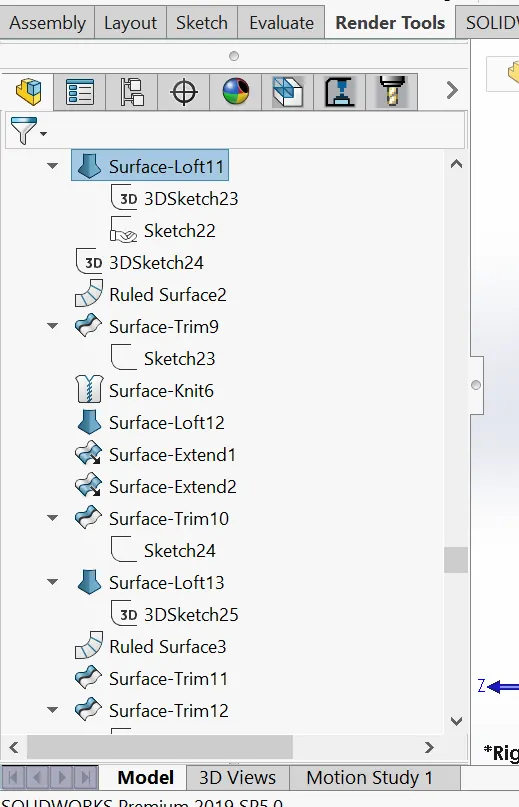
- Surface loft
- Surface trim
- Surface offset
- Surface extend
- Surface extrude
- Ruled Surface
- Sweep
- Revolve
- Chamfer
- Fillet
Please see terms and meaning for meaning of features
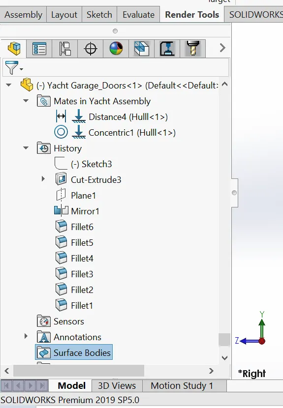
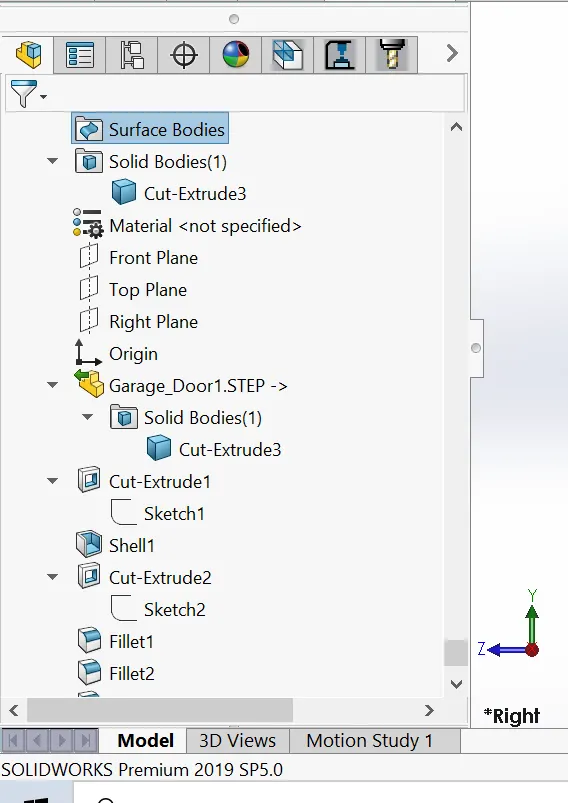
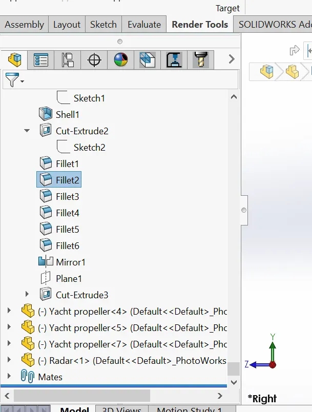
GARAGE DOOR
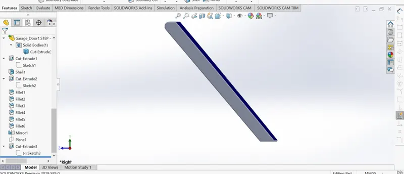
The garage door is the door that allows or restricts entrance to the garage. The garage protects items and properties that are kept in it against the elements. See below some of the features that were used in modeling of the Garage door.
- Cut Extrude
- Shell
- Mirror
- Fillet
Please see terms and meaning for meaning of features
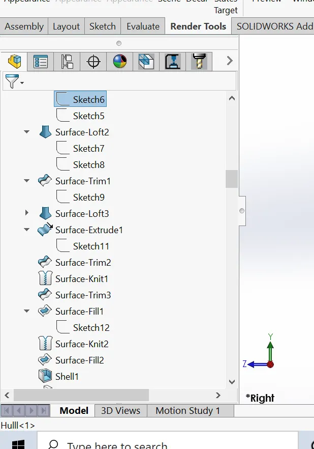
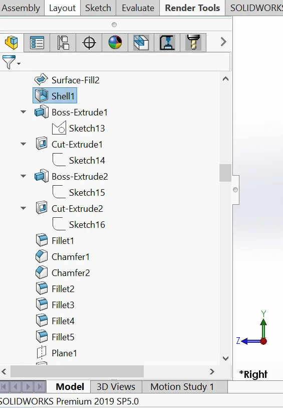
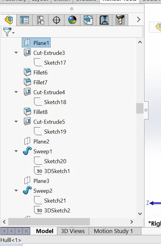
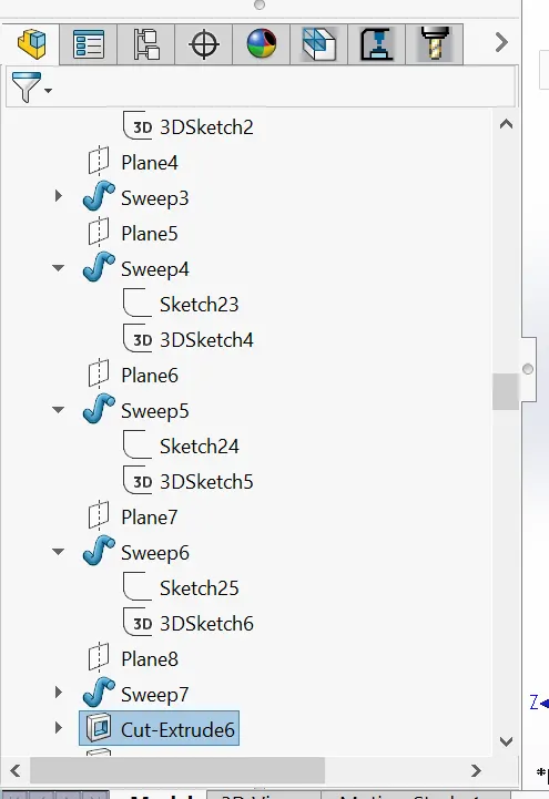
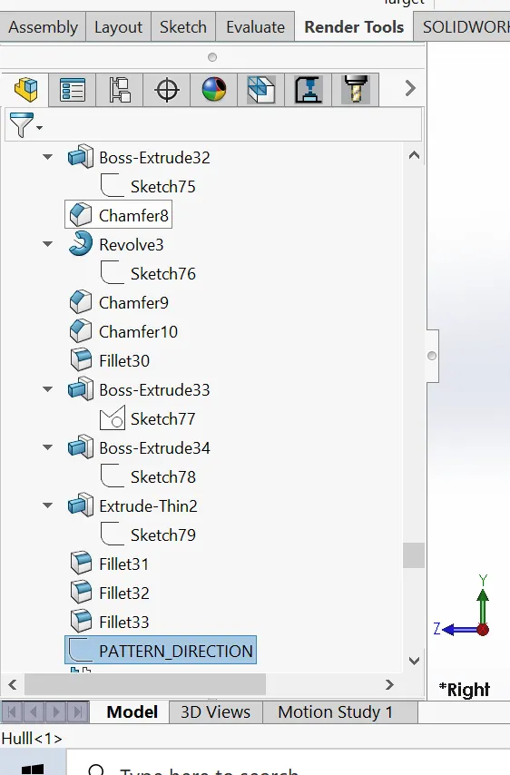
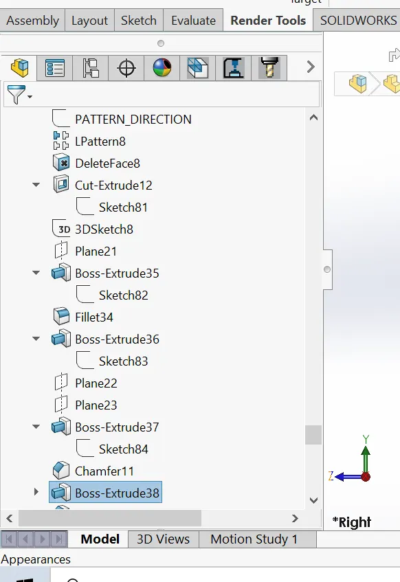
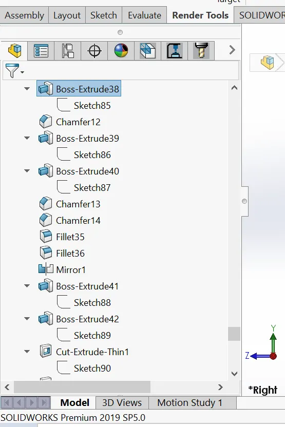
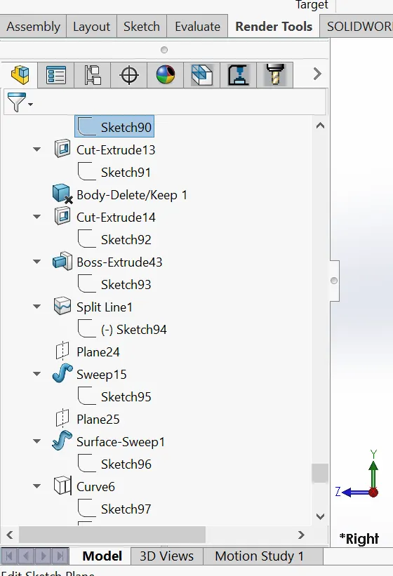
HULL
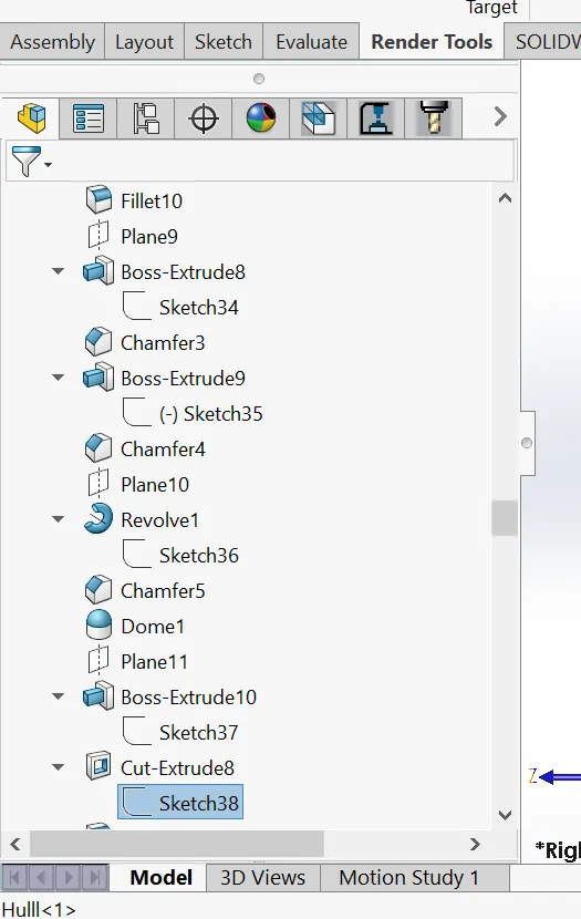
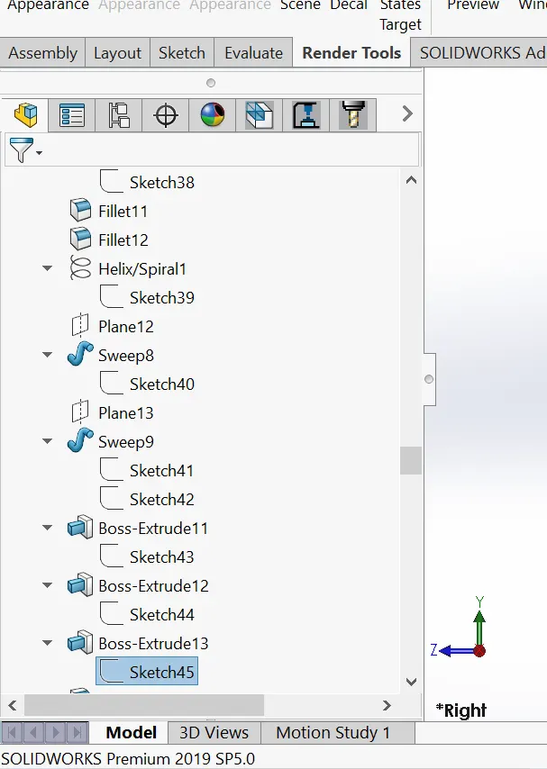
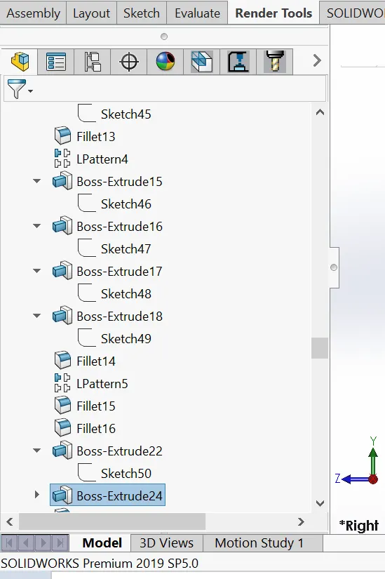
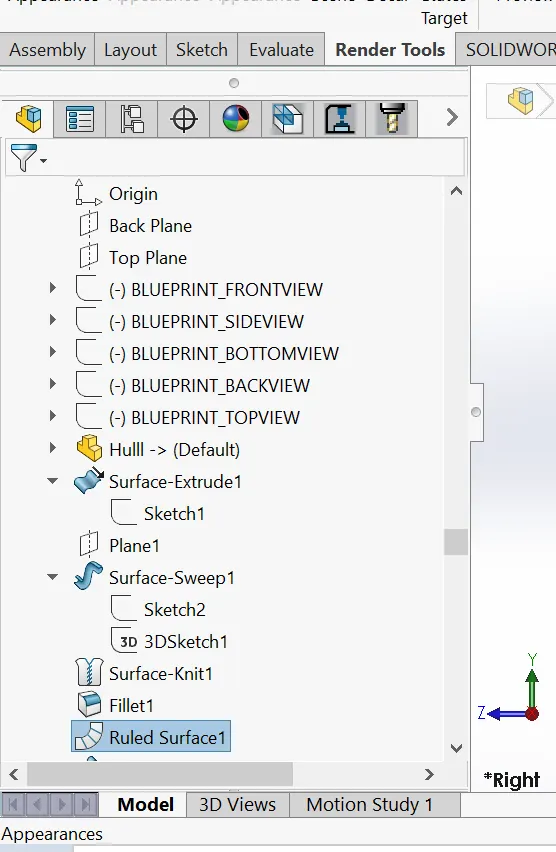
The hull is the watertight body of a Yacht, ship, boat, or flying boat. The hull may open at the top (such as a dinghy), or it may be fully or partially covered with a deck. The line where the hull meets the water surface is called the waterline. See below some features that were used in modeling the Hull.
- Boss Extrude
- Cut Extrude
- Fillet
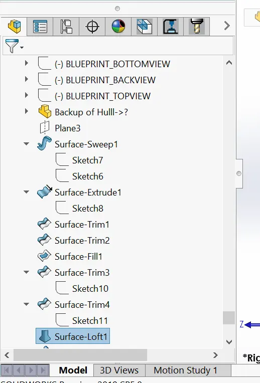
- Surface loft
- Surface trim
- Surface extrude
- Surface knit
- Surface fill
- Chamfer
- Sweep
- Revolve
- Helix and Spiral
- Linear pattern
- Projected curve
- Combine
Please see terms and meaning for meaning of features
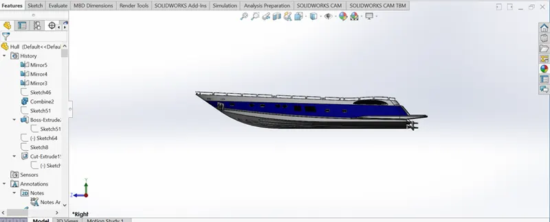
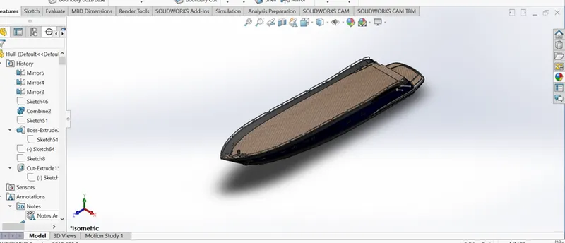
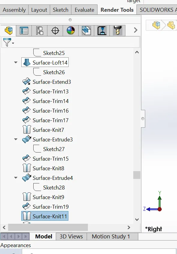
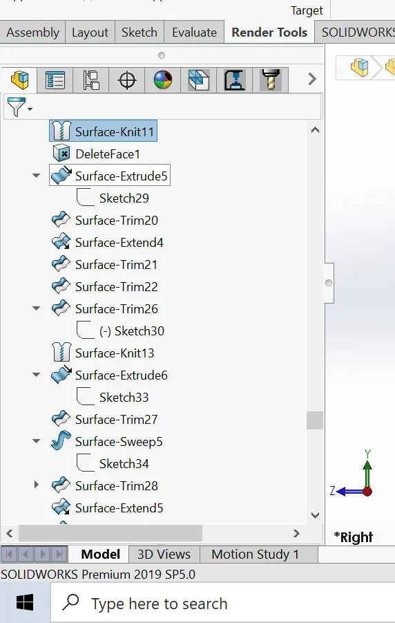
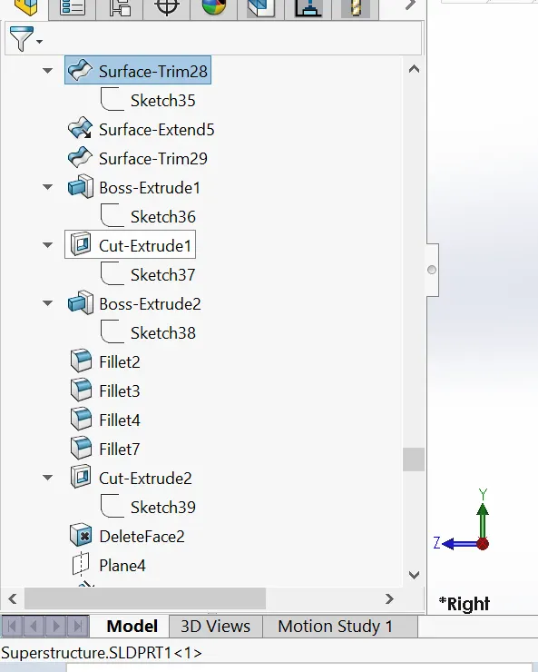
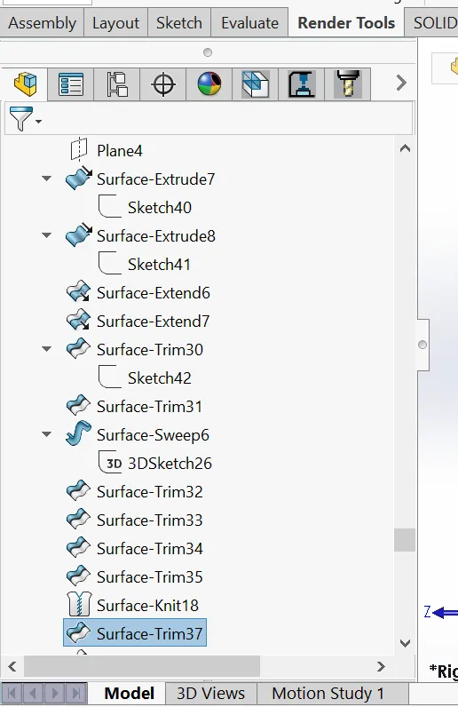
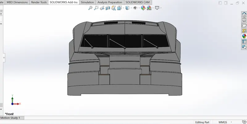
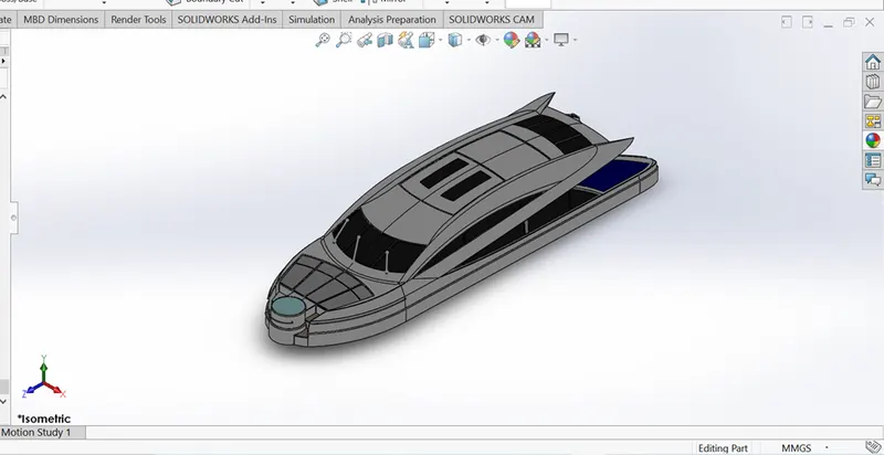
SUPERSTRUCTURE
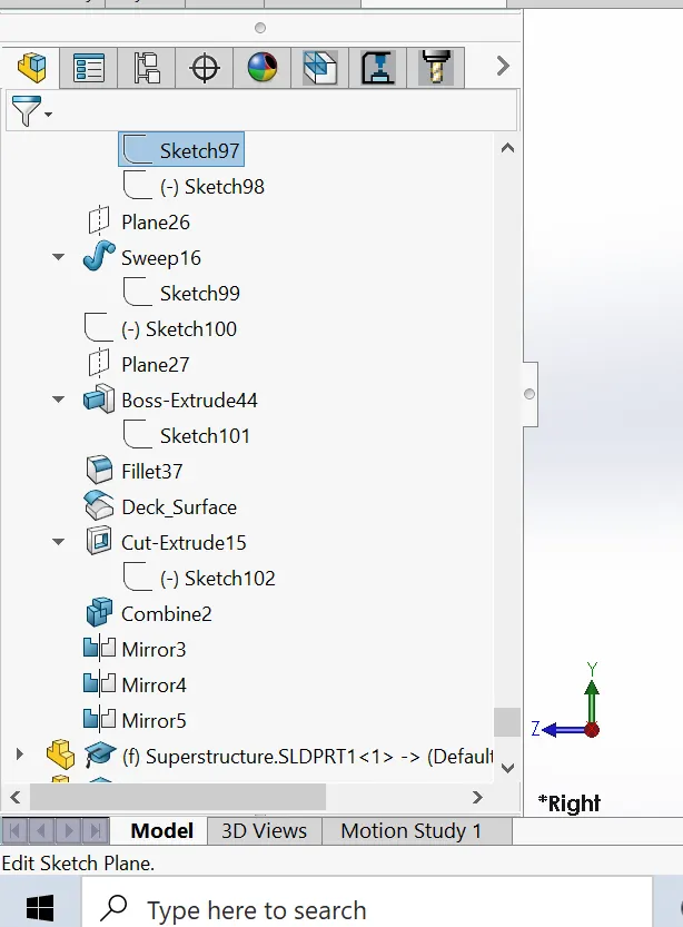
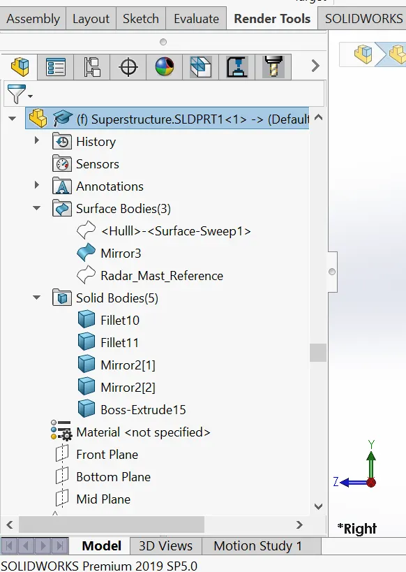
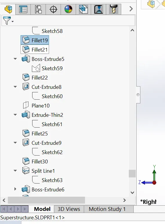
The superstructure consists of the parts of the Yacht, that project above her main deck. This does not usually include its masts or any armament turrets. See below some features that were used in modeling the Superstructure.
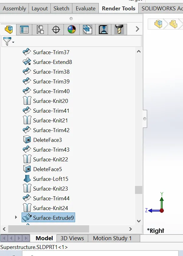
- Ruled surface
- Projected curve
- Surface trim
- Surface loft
- Surface fill
- Surface seep
- Surface knit
- Surface extrude
- Surface extend
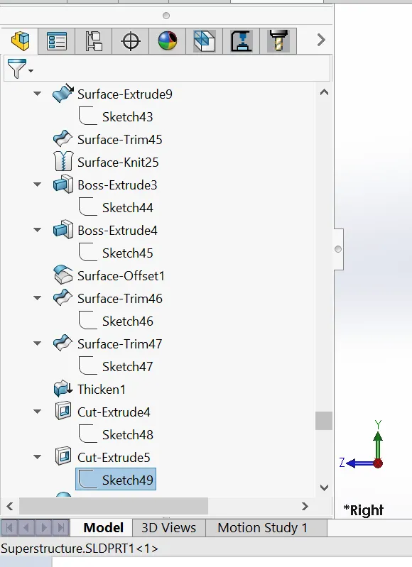
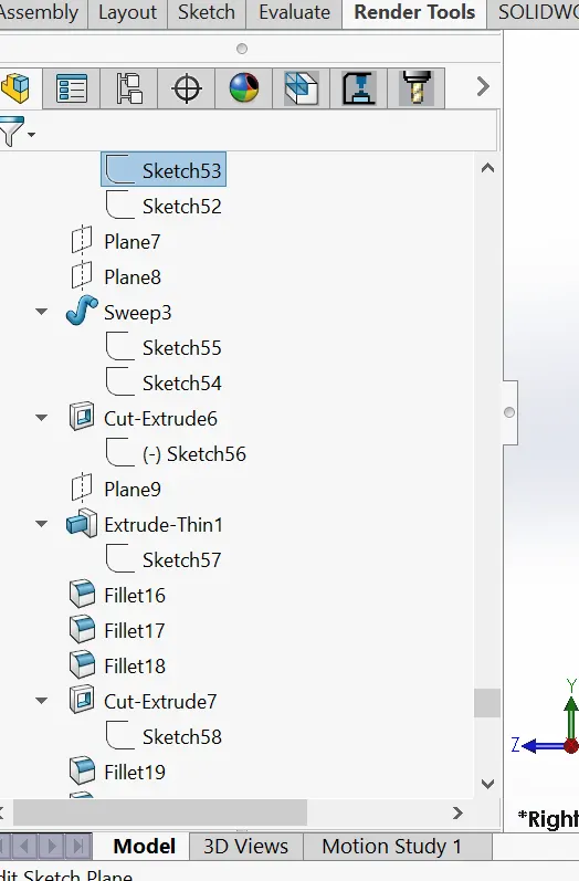
- Cut extrude
- Boss extrude
- Thicken
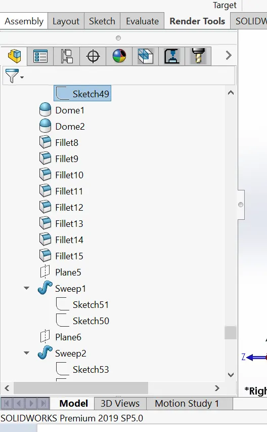
- Sweep
- Dome
- Split line
- Chamfer
- Fillet
Please see terms and meaning for meaning of features
ASSEMBLING OF A YACHT
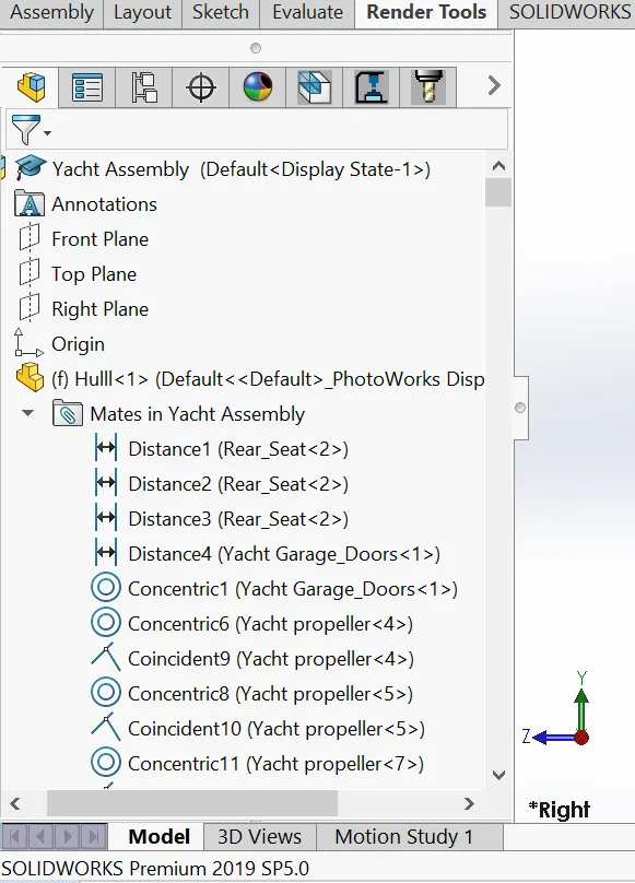
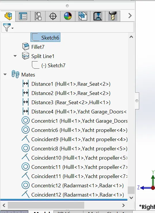
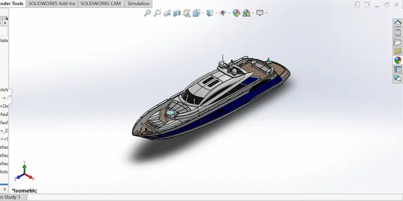
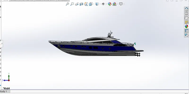
This involves bringing together/merging modeled part to the Hull via mates. Mates create geometric relationships between assembly components. As we add mates, we define the allowable directions of linear or rotational motion of the components. We can move a component within its degrees of freedom
RENDERING
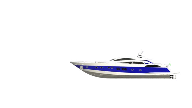
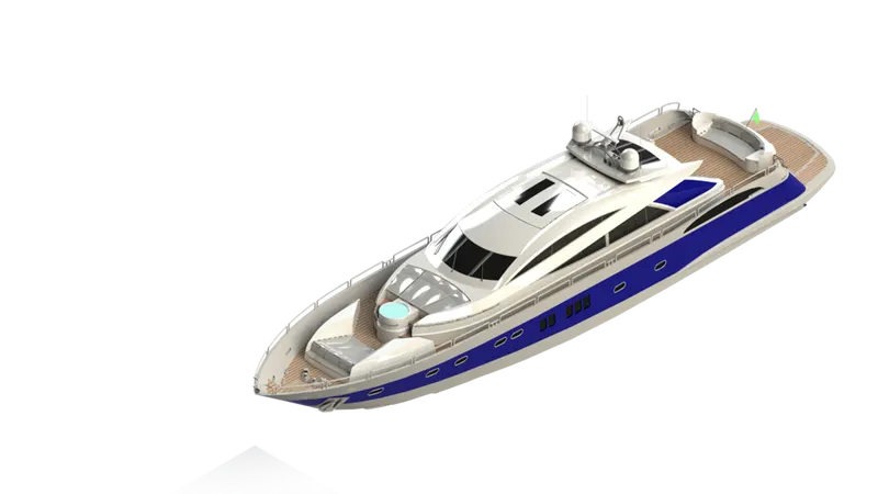
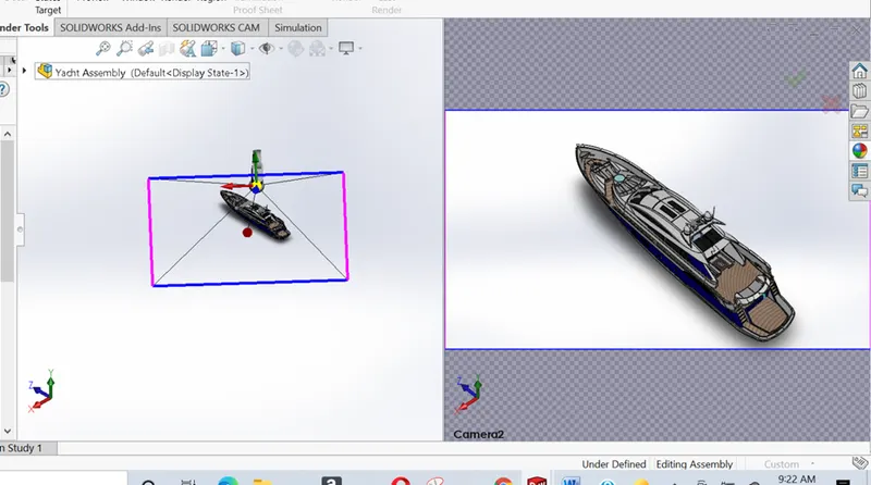
Photo-view 360 was used for rendering the model in this project.
PhotoView 360 is a SOLIDWORKS add-in that produces photo-realistic renderings of SOLIDWORKS models. The rendered image incorporates the appearances, lighting, scene, and decals included with the model
RENDERING WITH PHOTOVIEW 360
- With a model open, click Tools > Add-In and add in PhotoView 360.
- Start a preview in the graphics area or open the Preview window to see how changes you make to the model affect the rendering.
- Edit appearances, the scene, and decals to suit your model
- Edit lights as required
- Edit PhotoView Options for better outcome of your final rendering
TERMS AND MEANING
Extrude
A feature that linearly projects a sketch to either add material to a part (in a base or boss) or remove material from a part (in a cut or hole).
Cut
A feature that removes material from a part by such actions as extrude, revolve, loft, sweep, thicken, cavity, and so on.
Chamfer
Bevels a selected edge or vertex. You can apply chamfers to both sketches and features
Dome
A dome is a curved formation or structure. It is shaped like half of a sphere
Sweep
This creates a base, boss, cut, or surface feature by moving a profile (section) along a path.
Shell
A feature tool that hollows out a part, leaving open the selected faces and thin walls on the remaining faces.
Rebuild
This tool updates the document with any changes made since the last time the model was rebuilt.
Relation
A geometric constraint between sketch entities or between a sketch entity and a plane, axis, edge, or vertex.
Pattern
This repeats selected sketch entities, features, or components in an array, which can be linear, circular, or sketch-driven.
Model
The 3D solid geometry in a part or assembly document.
Mirror
A mirror feature is a copy of a selected feature, mirrored about a plane or planar face.
A mirror sketch entity is a copy of a selected sketch entity that is mirrored about a centerline
Loft
A base, boss, cut, or surface feature created by transitions between profiles.
Mate
It's a geometric relationship, such as coincident, perpendicular, tangent, and so on, between parts in an assembly.
Fillet
It creates a rounded internal or external face on the part. You can fillet all edges of a face, selected sets of faces, selected edges, or edge loops
Base
The first solid feature of a part.
Boss
This feature adds material to a part.
Assembly
A document in which parts, features, and other assemblies (sub-assemblies) are mated together.
Surface Knit
Combine two or more faces and surfaces into one
Surface Fill
Filled Surface feature constructs a surface patch with any number of sides, within a boundary defined by existing model edges, sketches, or curves
Surface sweep
Surface sweep are surfaces that are generated from a section curve positioned along a path.
Surface Extrude
Creating an Extrude surface
Surface Trim
To trim a surface where one surface intersects with another surface, a sketch or a plane
Surface Extend
You can extend a surface by selecting an edge, multiple edges, or a face. For edges, the surface extends along the plane of the edge. For faces, the surface extends along all edges of the face except those connected to another face.
Revolve
Revolves a selected sketch contour around an axis to create a solid feature.
Helix/spiral
A helix is a twisted, spiral shape, a helix is the height of one complete helix turn, measured parallel to the axis of the helix.
Combine
It’s a common function that allows you to add two bodies together, and keep the area that is common to them
Project Curve
Create a sketch on each of two intersecting planes, The two sketches (gray) project onto each other to form the 3D curve (green). The curve is used as a path for a sweep.
Linear Pattern
It is use to create multiple instances of one or more features that you can space uniformly along one or two linear paths
CONCLUSION
The parts of the Yacht were successful modeled, given appearances and assembled. Photo View 360 was used to render the Yacht. This project has definitely added to my knowledge on the use