Photo Realistic Rendering
MODELLING AND RENDERING OF AMERICAN CHOPPER WITH SOLIDWORKS
TABLE OF CONTENT
- Modeling Parts of Chopper
- Assembling Modeled Parts of Chopper
- Rendering
- a) With PhotoView 360
- b) With SOLIDWORKS Visualize
- Terms and Meaning
INTRODUCTION
Solidworks is an application that is use to create, edit, and visualize 3D models and detailed model drawings. It also gives you the options to choose the materials for your models as well as its appearances. In this project, we will be modelling parts of an American chopper as well as assembling the parts to create a complete model of an American chopper and then rendering the Chopper image.
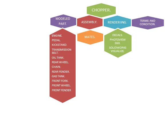
MODELLING PARTS OF AN AMERICAN CHOPPER
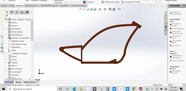
CHASIS
This is the skeleton of the Chopper, it’s the frame works that holds other parts of the model (Chopper) together. In modeling the chasis I had to use a lot of 2D spline, create multiple sketches as well as geometry, below are some of the features that were used in modeling the CHASIS.
- Sketch
- Split
- Sweeps
- Chamfer
- Curve
- Revolve
- Mirror
- Fillet
- Dome
Please see terms and meaning for meaning of features
ENGINE
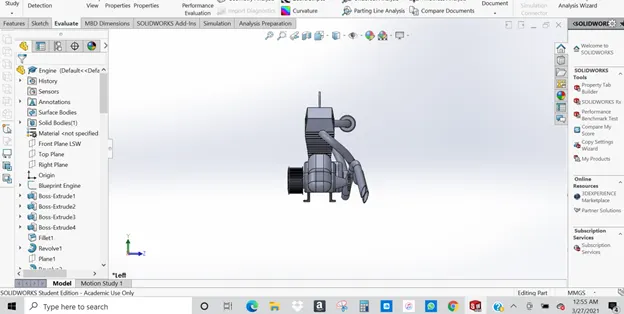
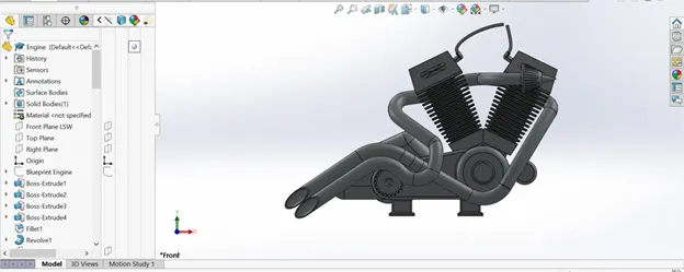
Is a machine with moving parts that converts power into motion. Creating an engine using solidworks involves creating a lot 2D splines, compulsive curves by using several 3D curves and also used projective curves in the creation of the engine exhaust. Below are some of the features that were used in modeling the Engine.
- Revolve
- Boss Extrude
- Cut Extrude
- Chamfer
- Dome
- Circular Pattern
- Sweeps
- Composite Curves
- Projected Curves
- Mirror
- Fillet
Please see terms and meaning for meaning of features
PEDAL
Pedal in the part of the chopper that the rider put his/her foots on, or rest the foots on when riding the chopper. The pedal is attached to the chasis of the chopper; see some features that were used in the creation of this pedal below.
- Sketch
- Bose Extrude
- Revolve
- Linear Pattern
- Fillet
- Dome
- Chamfer
Please see terms and meaning for meaning of features
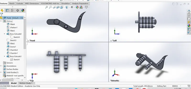
KICKSTAND
The kickstand is the part of the chopper that allows the chopper to be kept upright without leaning against another object or the aid of a person. The kickstand is a piece of metal that flips down from the chasis and makes contact with the ground. In creating this part, I made use of spline, pierce relation etc. Below are some of the features that were used in modeling the Kickstand.
- Boss Extrude
- Cut Extrude
- Loft
- Dome
- Fillet
Please see terms and meaning for meaning of features
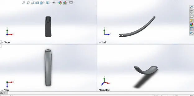
TRANSMISSION BELT
This belt is use to transmit motive force from the chopper engine. This is about the easiest part to model. It involve sketching the belt, offsetting it, do a boss Extrude and use your fillet. Please see terms and meaning for meaning of features
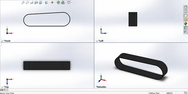
OIL TANK
Oil tank of the modeled American chopper is used to hold oil for lubrication and cooling of the internal engine components. Below are some of the features that were used in modeling the Oil Tank.
- Sketch
- Boss Extrude
- Combine
- Shell
- Fillet
Please see terms and meaning for meaning of features
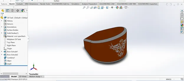
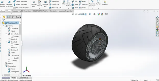
REAR WHEEL
This is the back wheel of the chopper that is used to propel the chopper through the motive force from the chain. see below for some of the features that were used in modeling of the Rear Wheel.
- Circular Pattern
- Cut Extrude
- Boss Extrude
- Cut Revolve
- Chamfer Combine
- Fillet
Please see terms and meaning for meaning of features
CHAIN
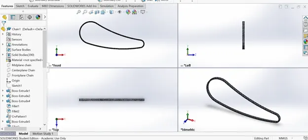
The Chains is a part of the chopper drive train that transmits the engine’s motive force to the back wheel. Created sketch blocks of inside links and outside links, and also pins to connect the inside and outside link plates, nicely applying a curve driven pattern also. See below some features that were used in modeling the Chain.
- Boss Extrude
- Circular Pattern
- Fillet
- Mirror
Please see terms and meaning for meaning of features
REAR FENDER
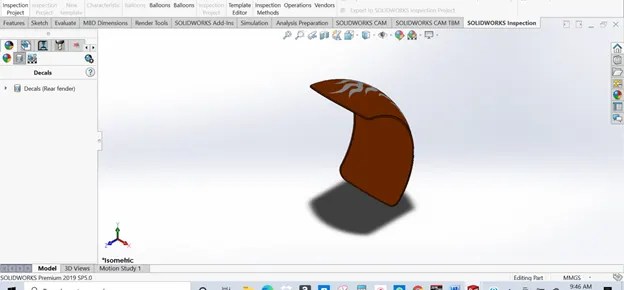
Primarily the purpose of the fender is to prevent sand, mud, rocks, liquids, and other road spray from being thrown into the air by the rotating tire. Rear fender was created using a 3point arc, offset, extend entities, trim entities, revolve, split, fillet and shell. Please see terms and meaning for meaning of features
GAS TANK
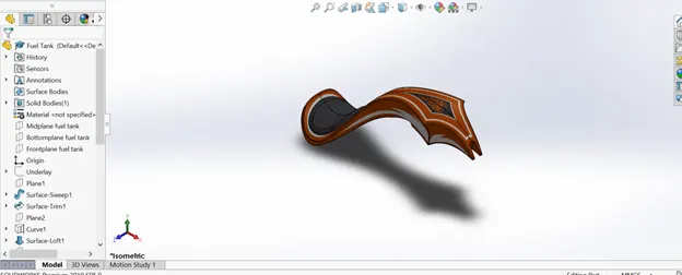
This is a safe container for flammable fluids that is used up by the engine. It was created using complex surfaces. Below are some of the features that were used in modeling the Gas Tank.
- Surface Extrude
- Surface Sweep
- Surface Trim
- Surface Knit
- Boundary Surface
- Shell
Please see terms and meaning for meaning of features
FRONT FORK
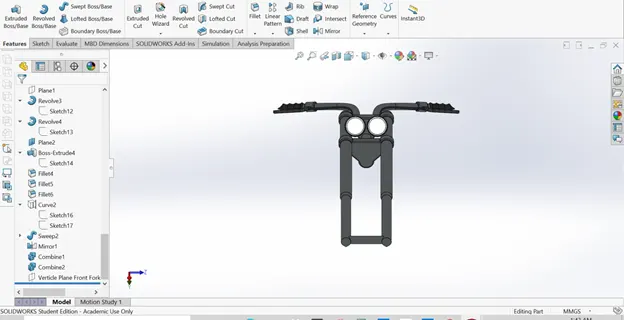
The front fork connects the Chopper's front wheel and axle to its Chasis, via a yoke, also known as a triple clamp, which consists of an upper yoke joined to a lower yoke via a steering stem, a shaft that runs through the steering head, creating the steering axis. In creating the front fork, several projective was use, and appearance was also used to make the head lamp glow. Below are some of the features that were used in modeling the front fork
- Boss Extrude
- Cut Extrude
- Cut Revolve
- Linear Pattern
- Sweeps
- Dome
- Combine
Please see terms and meaning for meaning of features
FRONT WHEEL
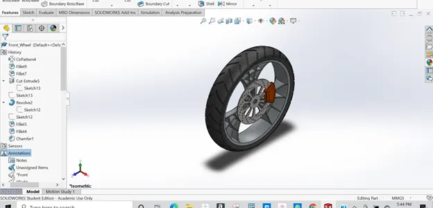
The main function of the front wheel is to take impact and steer the Chopper,3 point arc and 3 point center rectangle was used in the sketch for modelling this model, see below for some of the features that were used in modeling the front wheel.
- Revolve
- Boss Extrude
- Extrude Cut
- Circular Pattern
- Combine
- Fillet
- Chamfer
Please see terms and meaning for meaning of features
FRONT FENDER
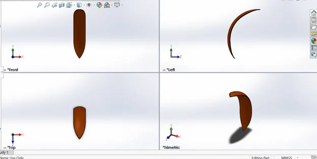
Front fender, like the rear fender, prevents sand, mud, rocks, liquids, and other road spray from being thrown into the air by the rotating tire. This model creation is almost to that of the rear fender. see below for some of the features that were used in modeling the front fender
- Revolve
- Dynamic Mirror
- Split
- Fillet
Please see terms and meaning for meaning of features
ASSEMBLING OF CHOPPER
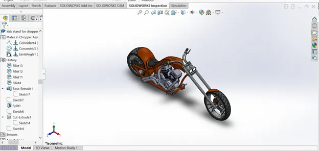
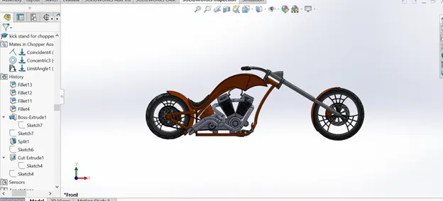
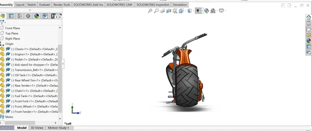
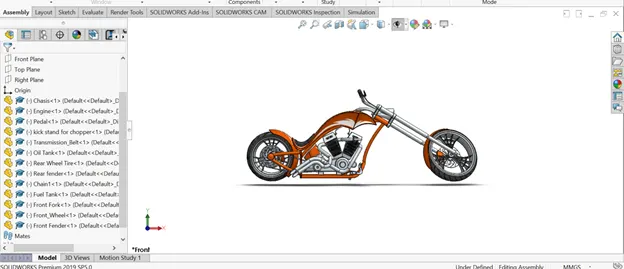
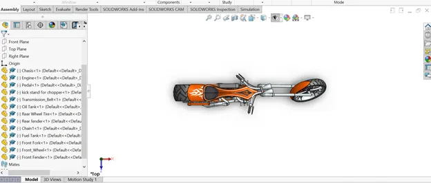
This involves bringing together/merging modeled part to the chasis via mates. Mates create geometric relationships between assembly components. As we add mates, we define the allowable directions of linear or rotational motion of the components. We can move a component within its degrees of freedom
RENDERING
Two types of tools were used for rendering the model in this project.
- PhotoView 360
- SOLIDWORKS Visualize
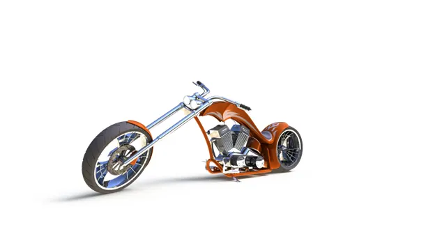
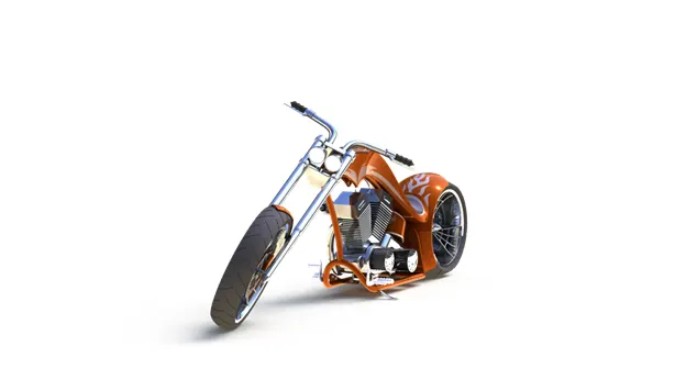
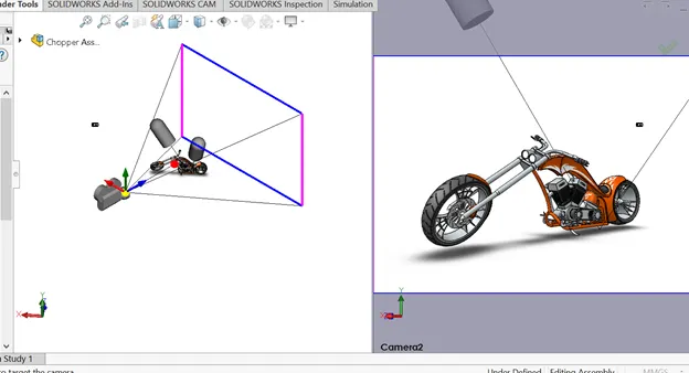
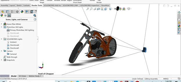
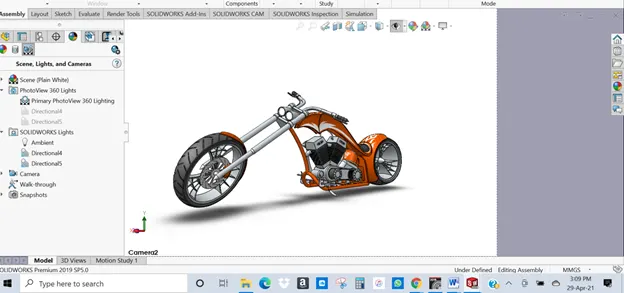
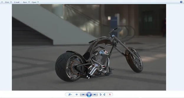
PhotoView 360 is a SOLIDWORKS add-in that produces photo-realistic renderings of SOLIDWORKS models. The rendered image incorporates the appearances, lighting, scene, and decals included with the model
RENDERING WITH PHOTOVIEW 360
- With a model open, click Tools > Add-In and add in PhotoView 360.
- Start a preview in the graphics area or open the Preview window to see how changes you make to the model affect the rendering.
- Edit appearances, the scene, and decals to suit your model
- Edit lights as required
- Edit PhotoView Options for better outcome of your final rendering
SOLIDWORKS VISUALIZE
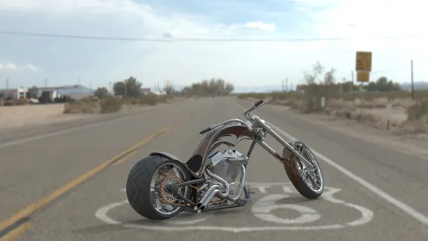
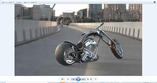
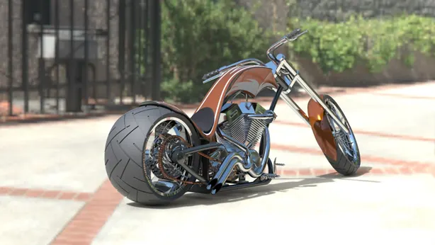
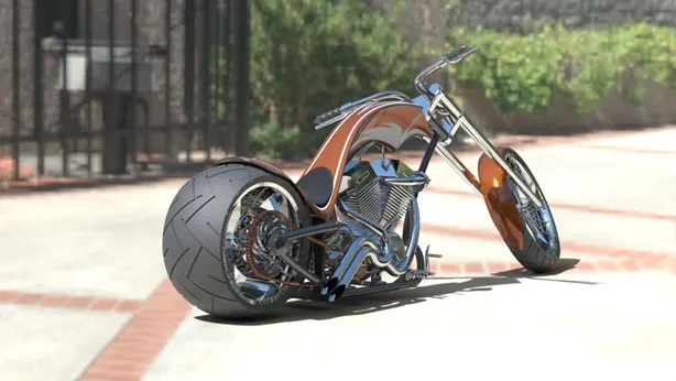
SOLIDWORKS Visualize picks up where PhotoView 360 leaves off by introducing an environment that is more similar to photography, versus technical rendering, with a focus on 3D data. The results are indistinguishable from photos, so they can actually be used directly for marketing

TERMS AND MEANING
Extrude
A feature that linearly projects a sketch to either add material to a part (in a base or boss) or remove material from a part (in a cut or hole).
Cut
A feature that removes material from a part by such actions as extrude, revolve, loft, sweep, thicken, cavity, and so on.
Chamfer
Bevels a selected edge or vertex. You can apply chamfers to both sketches and features
Dome
A dome is a curved formation or structure. It is shaped like half of a sphere
Block
A user-defined annotation for drawings only. A block can contain text, sketch entities (except points), and area hatch, and it can be saved in a file for later use.
Vertex
A point at which two or more lines or edges intersect
Sweep
This creates a base, boss, cut, or surface feature by moving a profile (section) along a path.
Shell
A feature tool that hollows out a part, leaving open the selected faces and thin walls on the remaining faces.
Rebuild
This tool updates the document with any changes made since the last time the model was rebuilt.
Relation
A geometric constraint between sketch entities or between a sketch entity and a plane, axis, edge, or vertex.
Pattern
This repeats selected sketch entities, features, or components in an array, which can be linear, circular, or sketch-driven.
Model
The 3D solid geometry in a part or assembly document.
Mirror
A mirror feature is a copy of a selected feature, mirrored about a plane or planar face.
A mirror sketch entity is a copy of a selected sketch entity that is mirrored about a centerline
Loft
A base, boss, cut, or surface feature created by transitions between profiles.
Mate
It's a geometric relationship, such as coincident, perpendicular, tangent, and so on, between parts in an assembly.
Fillet
It creates a rounded internal or external face on the part. You can fillet all edges of a face, selected sets of faces, selected edges, or edge loops
Base
The first solid feature of a part.
Boss
This feature adds material to a part.
Assembly
A document in which parts, features, and other assemblies (sub-assemblies) are mated together.
Surface Knit
Combine two or more faces and surfaces into one
Surface boundary
Creates surfaces that can be tangent or curvature continuous in both directions
Surface sweep
Surface sweep are surfaces that are generated from a section curve positioned along a path.
Surface Extrude
Creating an Extrude surface
Surface Trim
To trim a surface where one surface intersects with another surface, a sketch or a plane
Revolve
Revolves a selected sketch contour around an axis to create a solid feature.
CONCLUSION
In conclusion, the parts of American Chopper were successful modeled, given appearances and assembled. PhotoView 360 and SOLIDWORKS visualize was used to render the American Chopper respectfully. This project has also increase my Knowledge on the use of SOLIDWORKS applications, to sketch, convert 2D sketch to 3D models, giving appearance to models, assembling, rendering .etc. SOLIDWORKS is truly a great tool for modelling Design and I will surely recommend it for those interested in Modelling designs.