Radar Mast & Final Assembly of Yacht
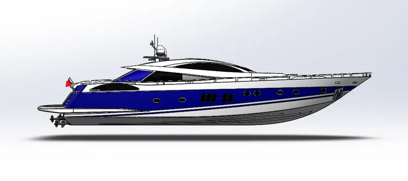
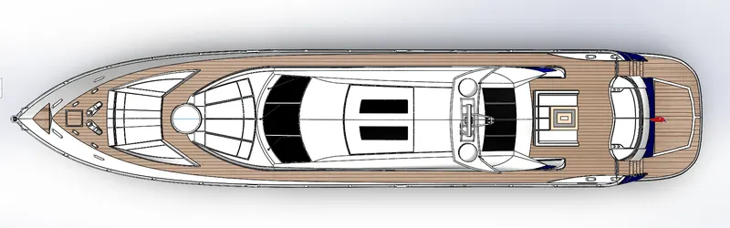
Designing, Modelling, Assembly and Photo-realistic Rendering of a Yacht
By :
Divesh Kumar.R
Objective:
- I wanted to learn about the solid modelling and surface modelling tools of the CAD software – SOLIDWORKS since SOLIDWORKS is a dynamic software used primarily in the R&D sectors SOLIDWORKS is widely used in the concept generation stage of production and It gives designers real-time results in product modelling. The projects and challenges that I’ve complete in this coursework will help me in improving my knowledge.
Introduction:
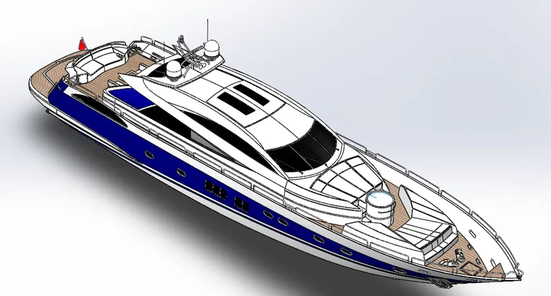
- I’ve sketch and build a complete Photo-realistic CAD model of a yacht using SOLIDWORKS.
- In this project I’ve learnt about how to create cut extrudes, revolve cuts, lofts, circular patterns, split, combine for modelling – how to Set up blueprints -Setting up of reference planes - curve generation - projected curve creation - understanding how to insert the parts in assembly workspace - Creation of mates - Difference between float and fix parts - Width mates application
- I’ve also learnt how to create photorealistic renderings with real time appearances and views.
Different parts I had to design to build the yacht on Solidworks are:
- Propeller
- Radar
- Blueprint
- Hull
- Garage door
- Front seats
- Middle seats
- Rear seats
- Radar mast
Once I’ve completed creating these parts, I’ve to start assembling them with applying appropriate mates , after completing the assembly I started doing photorealistic renderings with real time appearances and views.
Design Methodology:
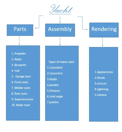
In this flow chart below I have explained how week by week I’ve designed every components of the yacht
Yacht
Features and properties which are used while designing the model of Yacht:
- First of all open a new part with model units set to millimetres.
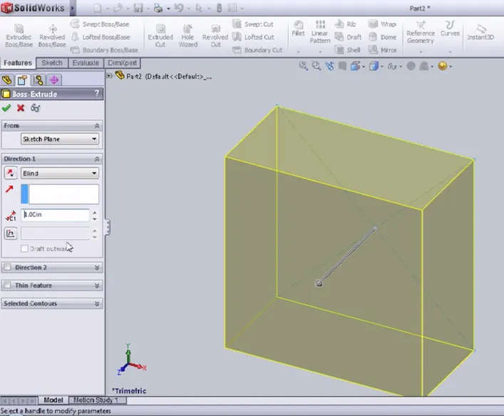
- Boss/Base Extrude Feature:
Is one of the important and very useful tool in Soildworks CAD software to create solid 3D models . It extrudes a sketch or selected sketch contours in one or two directions to create solid feature. That means, if you have closed contour sketch drawing, then you can add materials to that contour and convert it into 3D model via boss/base extrude. However, that is not always the case, which is why the Extrude Boss/Base feature is such a handy tool. Whether you need to extrude something complicated such as up to a feature of another part, or something simple like creating the block, the extrude feature has it all
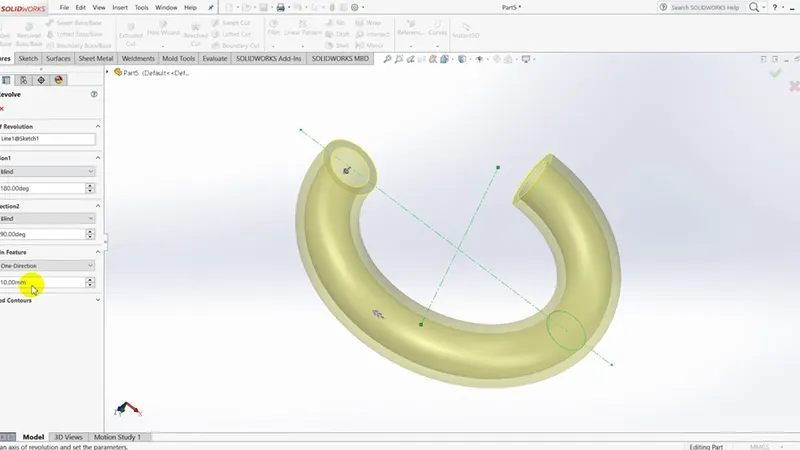
2.Boss/Base Revolve Feature:
Revolved Boss or Base is a SolidWorks feature tool which is used to create solid 3D model around an axis. You can revolve the sketch around an axis to add materials to it. You can access revolved boss/base from both command manager and menubar.
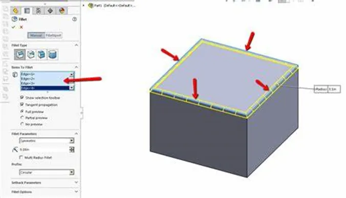
- Fillet:
Fillet/Round creates a rounded internal or external face on the part. You can fillet all edges of a face, selected sets of faces, selected edges, or edge loops. There are four types of fillet 1.Constant size fillet 2. Variable size fillet 3. Face fillet 4. Full round fillet . Go to feature then fillet click then show mode type (manual/file expert) fillet type choose any one which is required and then selection window select faces/edges and then fillet radius c
- Extrude Cut:
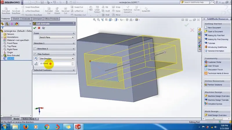
Extrude cut is another cool feature which helps to remove materials from the 3D model. It is just opposite to extrude boss/base feature, because it cuts a sketch profile while extruding. You can cut in both directions and mainly used for creating holes, channels, slots etc .Under the “From” header there is a drop-down list containing a variety of options of where to start the Cut-Extrude from.
- Shell:
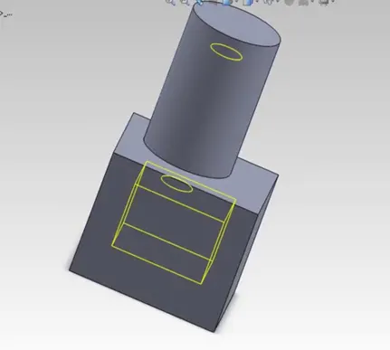
SolidWorks shell tool is mainly used for shelling process, in which the material removed from the inner body of model by keeping small thickness and results a hollow model. Using this tool, you can make either completely closed hollowed model or one face opened type. The shell tool hollows out a part, leaves open the faces you select, and creates thin-walled features on the remaining faces. If you do not select any face on the model, you can shell a solid part, creating a closed, hollow model. . You can also shell a model using multiple thicknesses.
6 . Sweep Bose /Sweep Cut:
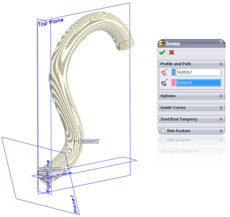
Solidworks Swept boss is one of the useful features which help to sweeps a closed profile through an open or closed path. That means, if you have closed profile (e.g: circle) and have a open or closed path (e.g: two curved line or rectangle); then you can sweeps the closed profile to make your desired part using Swept boss feature.Adding materials by sweeping shape through a designated path. Applying sweep boss we need to be 2sketch usually in two different planes .sweep cut is opposite to the sweep boss.here we can removing materials by sweeping a shape through a designated path . Set the Property Manager options based on the sweep cut feature. To open this Property Manager: Open a part that has either a closed profile sketch and a sketch path, or a part with a sketch line, edge or curve on the model that you can specify as a path.
- Loft Boss/Loft Cut:
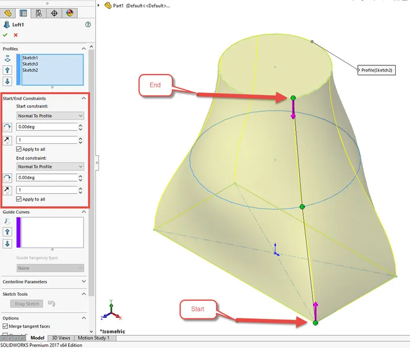
The loft feature is an important tool for (surface) modelling in Solid Works. The loft feature creates a shape by making transitions between multiple profiles and guide curves. This tool is very valuable for modelling complex surfaces loft cut is a solid works features tools which helps to cut or remove material between two or more profile.
.
- Linear Pattern:
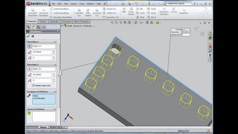
linear patterns to create multiple instances of one or more features that you can space uniformly along one or two linear paths. To create a linear pattern: Create one or more features to replicate. Click Linear Pattern (Features toolbar) or Insert > Pattern/Mirror > Linear Pattern
- Circular pattern:
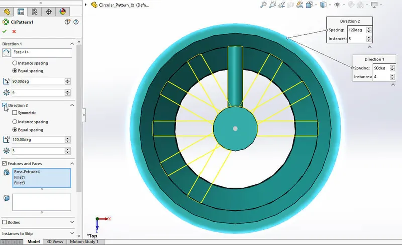
Pattern is based on one feature. Color of the pattern or any faces on any pattern instances have not been changed. The feature colors are not inherited if you pattern or mirror multibody parts. Create one or more features to replicate. Click Circular Pattern (Features toolbar) or Insert > Pattern/Mirror > Circular Pattern
- Mirror:
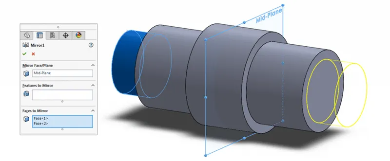
Using the Mirror Part feature lets you create a left hand version of the existing part without having to model it from the ground up. You can use the mirrored part in an assembly without having to use the original part . Creates a copy of a feature, (or multiple features), mirrored about a face or a plane. You can select the feature or you can select the faces that comprise the feature. Bodies to mirror . Select a body in a single model or multibody part to create a mirror entity.
11.Projected Curve:
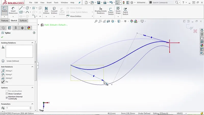
To project a curve: Click Project Curve on the Curves toolbar, or Insert > Curve > Projected. Under Direction of Projection , select a plane, edge, sketch, or face as the direction of the projected curve. Under Projection Faces , select the cylindrical face on the model where you want to project the sketch. A projected curve is typically used either in sweeps and lofts as path or guide curve. There are two types of projected curves: Sketch on Sketch: Use two sketches to make a single curve. Another is sketch on surface.
- Reference Geometry:
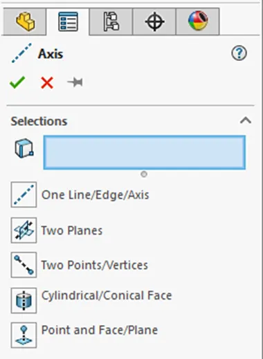
Reference Geometry includes reference planes, axes, coordinate systems, and points. .The Reference Geometry command lives on the Features toolbar, but you can also access it from Insert > Reference Geometry. The Reference Axis Property Manager includes a Selections box where you will define your Reference Axis. The Reference Axis Property Manager includes a Selections box where you will define your Reference Axis. The combinations of these selections that will fully define the Reference Axis are described and depicted below the Selections box.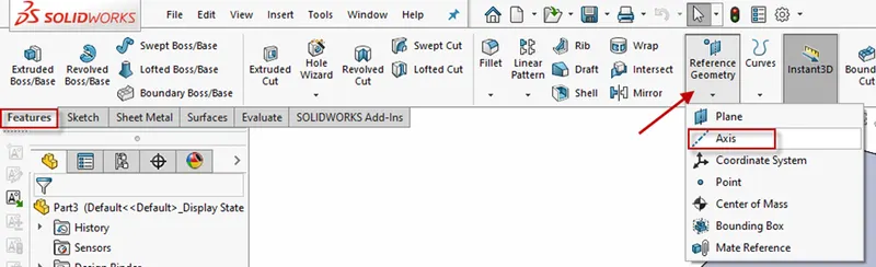
- COMBINE:
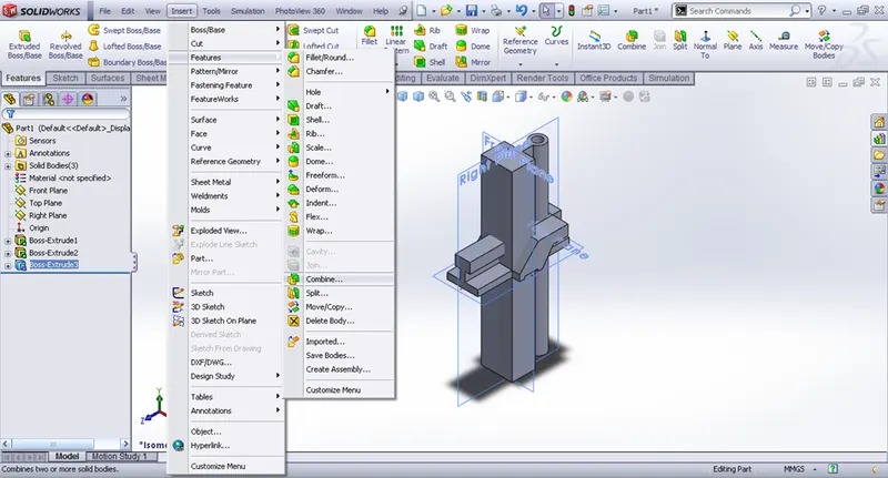
In the PropertyManager, under Operation Type, select Add. For Bodies to Combine, select the bodies to combine. You can select bodies in the graphics area or the Solid Bodies folder in the FeatureManager design tree. Click Show Preview to preview the feature. Click . Search 'Combining Bodies - Add' in the SOLIDWORKS Knowledge BaseThe Combine feature lives under Insert>Features>Combine. The common function allows you to add two bodies together, and keep the area that is common to them. To use this feature, we will select the common button, and then under Bodies to Combine, select the two bodies .
- DOME :
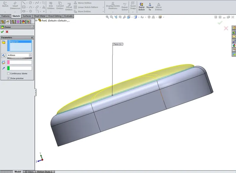
The Parameters in the dome Property Manager include: Faces to Dome. Select one or more planar or non-planar faces. You can apply domes to faces whose centroid lies outside the face. This allows you to apply domes to irregularly shaped contours.
- SPLIT :
Use the Split feature to create multiple parts from an existing part. You can create separate part files, and form an assembly from the new parts. When you edit split or saved bodies features, you can assign bodies by selecting from a list of derived parts, or by assigning them to other stored part files.
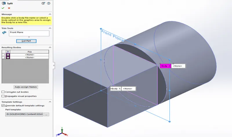
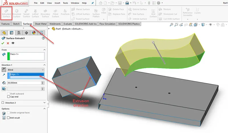
- Extrude Surface:
Using the SOLIDWORKS Surface Extrude feature, we can extrude the boundary edges of a face of a solid body or edges of a surface body in a customized direction. When we run the Extruded Surface command, two things can happen: Either a sketch is active or preselected or no sketches exists. In case no sketches exists or is selected, a message in yellow color shows in the property manager window on the left. The message is guiding us to select a sketch or a planar face to start drawing a sketch for extrusion purpose. In addition, the message guides us to extrude from a 3D face or use “Alt + planar face” to extrude.
17.Reveloved surface:
command is very useful command to create 3D geometries effectively in Solidworks. Also Solidworks provides a similar command to create surfaces called ‘Revolved Surface’ command. To create a revolved surface:
- Sketch a profile and a centerline around which to revolve the profile.
- Click Revolved Surface (Surfaces toolbar) or Insert > Surface > Revolve.
- Set the PropertyManager options.
- Click OK
.
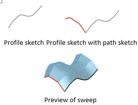
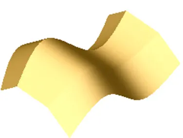
18.Swept surface
To create a swept surface:
- Create planes for sketching the sweep profile, sweep path, and if necessary, the guide curves.
- Sketch the sweep profile and path on the planes that you created.
You can also sketch the sweep path on a model face or use a model edge for the path.
- If you are using guide curves, create coincident or pierce relations between the guide curves and the profile.
- Click Swept Surface (Surfaces toolbar) or Insert > Surface > Sweep.
- Set the PropertyManager options.
- Click OK.
19.Planar surface:
You can create planar surfaces from these items:
- A non-intersecting closed sketch
- A set of closed edges
- Multiple co-planar parting lines
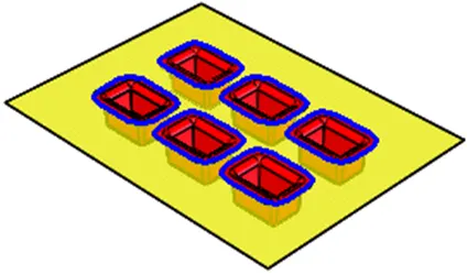
- A pair of planar entities such as curves or edges
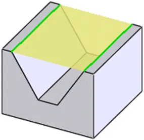
Creating a Planar Surface from a Set of Closed Edges
To create a planar surface bounded by a set of closed edges in a part:
- Click Planar Surface (Surfaces toolbar) or Insert > Surface > Planar.
- In the PropertyManager, select a set of closed edges in a part for Bounding Entities. All edges in the set must be on the same plane.
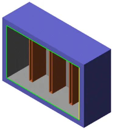
Click OK.
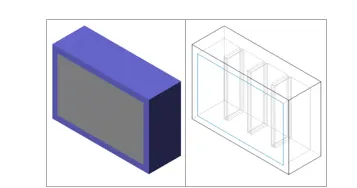
- Creating a Bounded Planar Surface from a SketchTo edit the planar surface, right-click the surface and select Edit Feature.
To create a bounded planar surface from a sketch:
- Create a non-intersecting, single contour, closed sketch.
- Click Planar Surface (Surfaces toolbar) or Insert > Surface > Planar.
- In the PropertyManager, select the sketch in the graphics area or FeatureManager design tree for Bounding Entities. Click OK .
- Click OK
20.Lofted surface:
To create a lofted surface:
- Create a plane for each profile section of the loft.
The planes do not need to be parallel.
- Sketch the section profiles on the planes. You can create all section and guide curve sketches inside a single 3D sketch.
- If necessary, create guide curves.
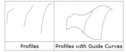
- Click Lofted Surface (Surfaces toolbar) or Insert > Surface > Loft.
- Set the PropertyManager options.
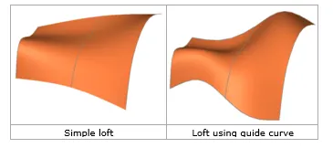
- Click OK .
21.Offset surface
The Offset Surface tool creates a new surface body from an existing set of faces. The faces may be solid or surface faces.
To create an offset surface:
- Click Offset Surface (Surfaces toolbar) or Insert > Surface > Offset.
- In the PropertyManager:
- Select surfaces or faces in the graphics area for Surface or Faces to Offset .
To select the entire model, click Edit > Select All.
- Set a value for Offset Distance.
You can create an offset surface with a distance of zero.
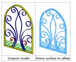
- Select Flip Offset Direction to change the direction of the offset.
- Click OK .
If the Offset Surface tool identifies faces that it cannot offset, it lists the failing faces in Offset Parameters. The preview updates to show the failing faces in red. When offset surfaces fail, it is usually because the offset distance is greater than the smallest curvature on the face.
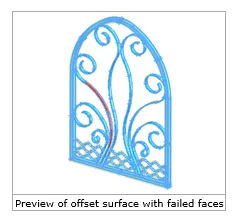
Faces sometimes fail because:
- Their offset surface includes an area with a radius of curvature that is less than the offset distance.
- They self-intersect.
- They interfere with nearby faces.
- The offset surfaces are not connected, for example, because the offset has broken references or is based on faces from multiple parts.
- In the PropertyManager, click Remove All Failing Faces.
The preview updates to show an offset surface with gaps caused by removing the failed faces.
- Click OK to create the offset surface with gaps.
- You can continue to adjust the offset surface by:
- In Offset Parameters, right-click Clear Selections to return to the model's original state.
- Enter a smaller value to reduce the Offset Distance.
- Click OK .
You can repair gaps in a Surface-Offset feature by manually adjusting the offsets of the failed faces and adding them back individually into the feature.
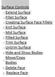
22.Surface control:
Under surface control I’ve used these commands to develop the yacht
. MATE :
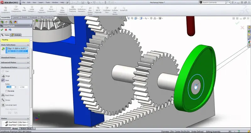
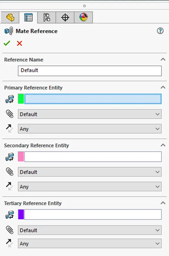
The SOLIDWORKS Mate tool is used for joining parts in an assembly to simulate how they fit and move together. Find out how to mate like a pro in this tutorial… When we create a part in SOLIDWORKS, the position of each body is defined in x , y, z space Mates is the parametric relationship between two or more components used in SolidWorks assembly feature. It helps to add degrees of freedom to your components as per the design. Mates function helps to link the components to assembly file and helps to add particular constrains as per the working of the parts
We’ve seen almost all the Features and properties which have been used while designing the model of American chopper Bike. Now we will discuss all the part component step by step:
1.Propeller:
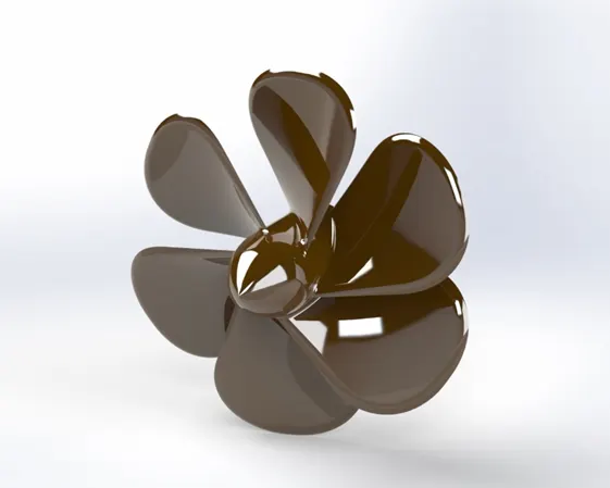
Create a new 2D sketch based on the Mid plane of the propeller and make sure They are in relation to each other and dimensioned correctly. Create an revolve by selecting the sketch and & revolve. Using surface loft create the fins of the propeller ,use fillet tool to give the propeller a smooth finish, circular pattern the fins with appropriate spacing . select appearance tab specify the material for the propeller. Save it as propeller.
2.Radar:
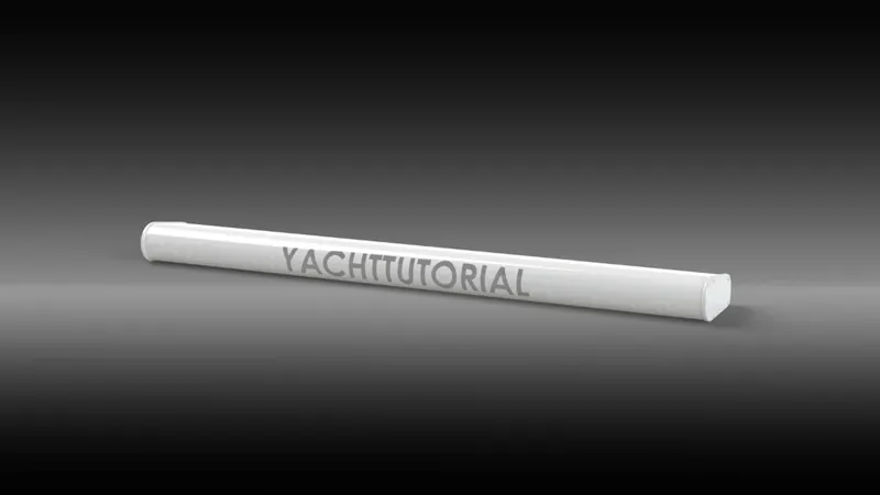
Create a new 2D sketch on the front plane of the radar, and extrude the sketch. Use fillets to obtain the proper shape, after creating a plane create a 2D sketch based on the surface by offsetting it and extrude the end portion and add fillets. sketch pattern the screws created and mirror with the midplane. Use extrude cut to create fonts on the radar if necessary .save as Radar
3.Blue prints:
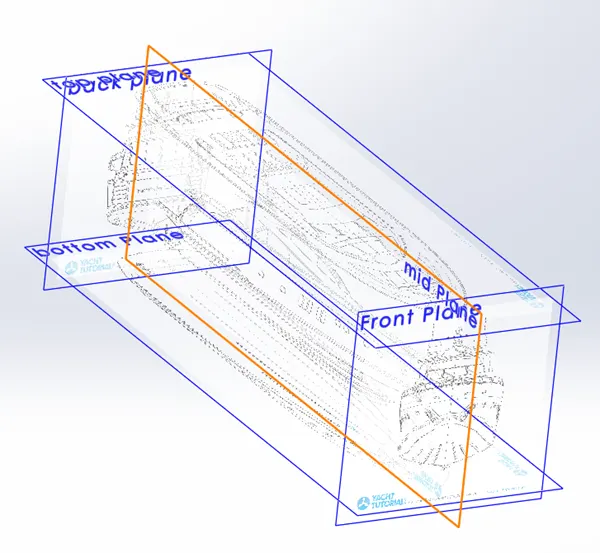
Create New planes according to the availability of the blueprints with exact dimensions with reference to the origin place all the blue print images appropriately by using sketch picture feature and then save the file as yacht blueprint.
4.hull:
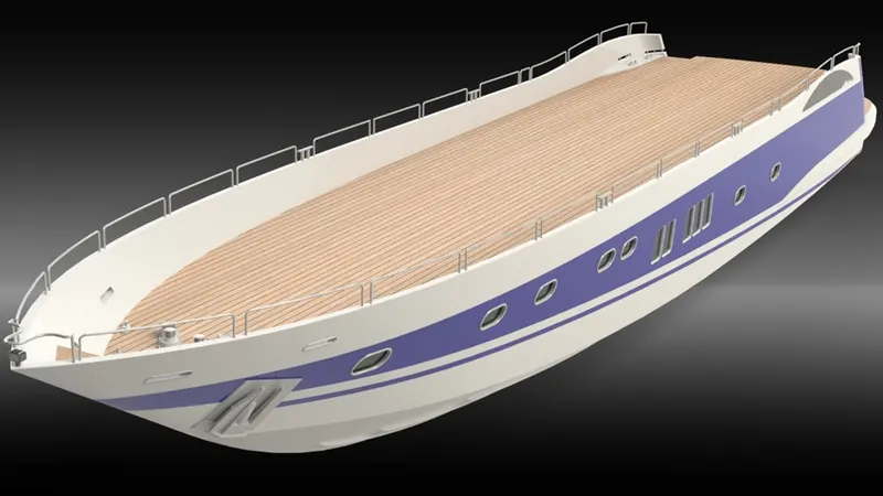
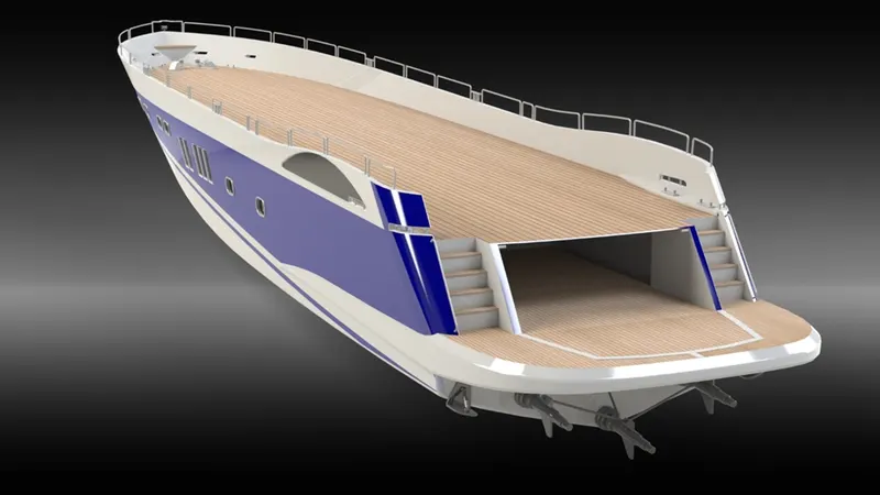
Using the blueprint draw a sketch on the midplane of the hull to generate one half of the hull using spline generate the sketch according to the blueprint and generate the curves by creating sketch on different planes surface loft the projected curve and with the help of blueprints start generating varies other components of the part and dimension them appropriately and use the proper relations, trim the unwanted surfaces by using surface trim feature and Knit the surfaces created and then convert them into a solid body after that create the sketch split the windows in the surface of the hull and create reference plane in each window to sweep a circular profile in the edge of the windows ,then start sketching the profile to create the anchor then extrude the part from the surface of the hull step by step after one end of the hull will be created mirror it then use fillets &chamfer on edges to give a neat representation of the anchor project the trailing reference by creating a sketch on top and midplane with the reference and the sweep the circular profile with the projected line as reference ,then start sketching the profile for the steps then cut-extrude the profile keeping blueprint as reference and use fillets to of the appropriate radius to obtain the exact geometry oh the profile use helix/spiral to generate the the rope of the anchor and other subsystems by revolve & extrude , mirror the generated one half of the hull with midplane as reference select appearance tab and add colours and decals to the hull . Save the part as hull
5.Garage door
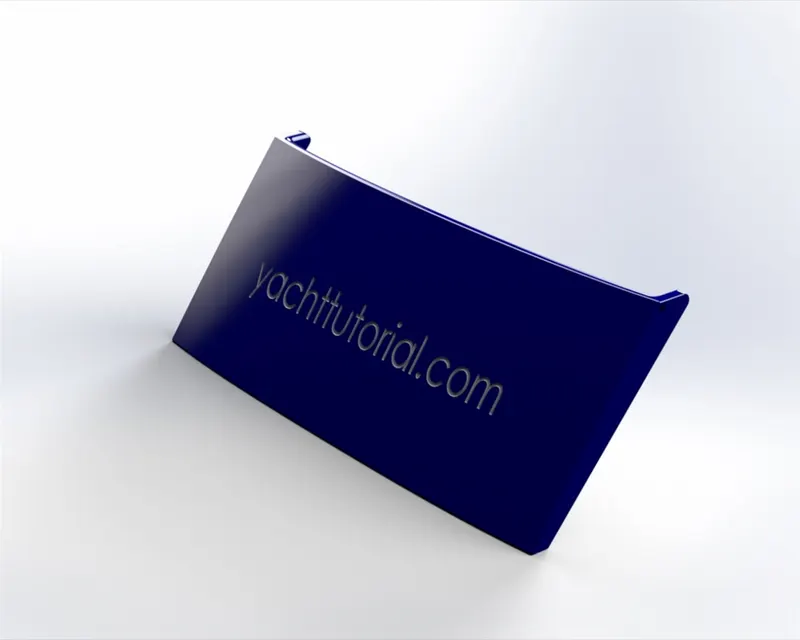
Import the solid body which has been cut from hull and saved as garage door cut the solid body according to the orientation of the garage door start adding fillets to the door & chamfer as well, now mirror the one side of door with the midplane use cut extrude to create font on the surface of the garage door add colour to the garage door by selecting colour on appearances tab .save as garage door
- Front Seats:
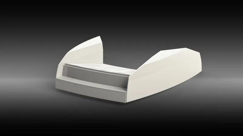
Import the hull surface and with the help of blue prints start sketching keeping the hull surface as base , by using lofted surface , surface extrude, sweep surface create the front seats one side of the whole part and convert it onto a solid body ,the mirror the one side with keeping the mid surface as the plane to mirror add appearances by selecting colours or material in appearances tab .save as front seats
7.Middle seats:
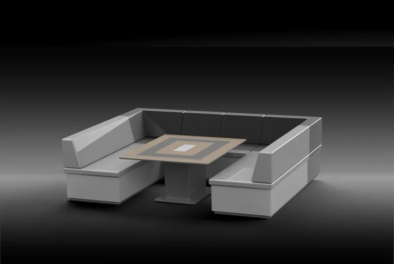
Import the hull surface and with the help of blue prints start sketching keeping the hull surface as base , by using lofted surface , surface extrude, sweep surface create the middle seats one side of the whole part and convert it onto a solid body ,the mirror the one side with keeping the mid surface as the plane to mirror add appearances by selecting colours or material in appearances tab ,save as middle seats
- rear seats:
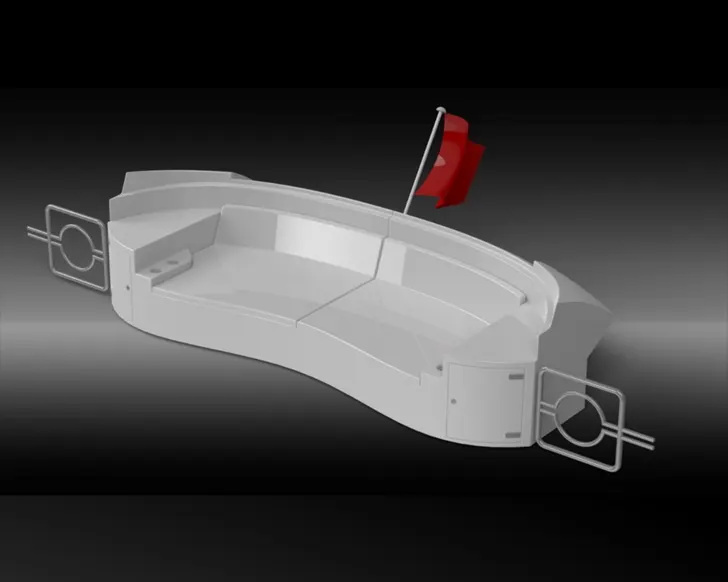
Import the hull surface and with the help of blue prints start sketching keeping the hull surface as base , by using lofted surface , surface extrude, sweep surface create the rear seats one side of the whole part and convert it onto a solid body ,create the gate like structure at the end and,the mirror the one side with keeping the mid surface as the plane to mirror add appearances by selecting colours or material in appearances tab .save as rear seats
- superstructure:
Import the hull surface and with the help of blue prints start sketching keeping the hull surface as base , by using lofted surface , surface extrude, sweep surface ,trim surface ,extend surface , fill surface , it’s a complex structure and should be careful while designing ,create the superstructure one side of the whole part and convert it onto a solid body ,the mirror the one side with keeping the mid surface as the plane to mirror add appearances by selecting colours or material in appearances tab. Save as superstructure
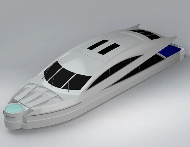
10.Radarmast:
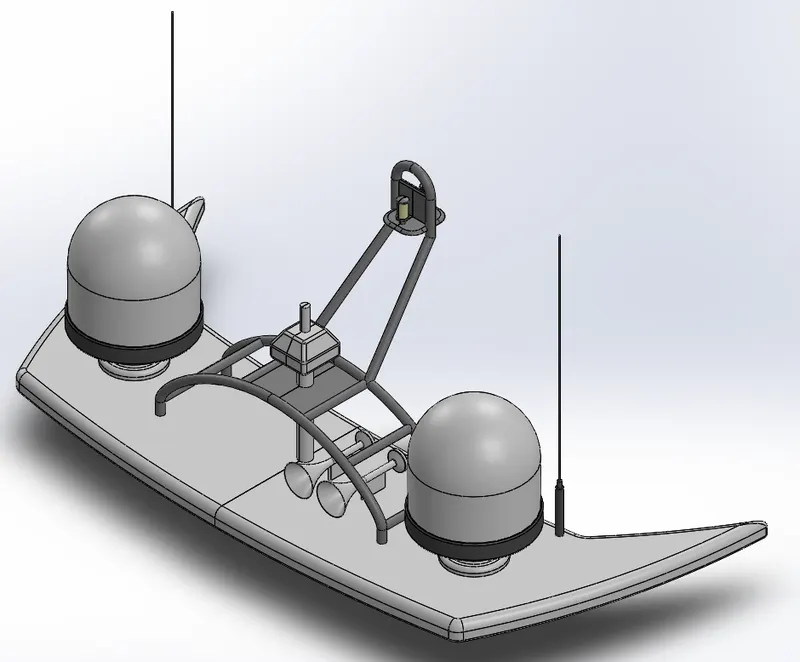
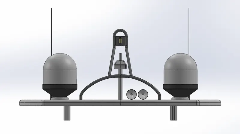
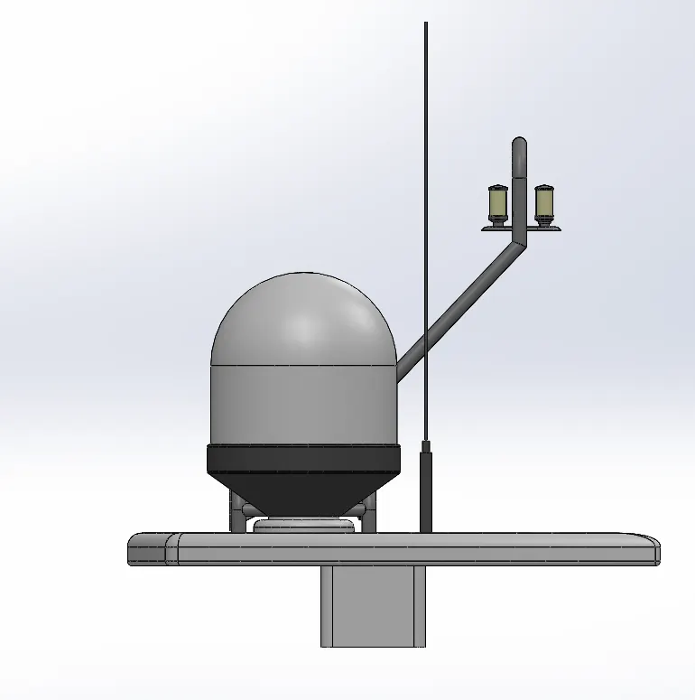
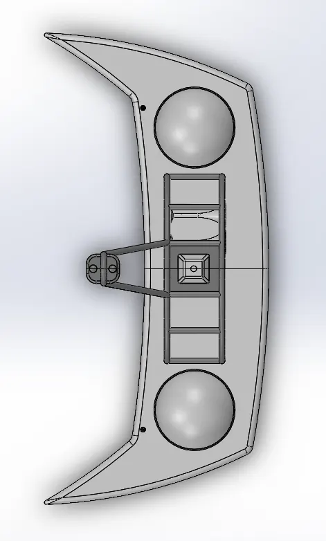
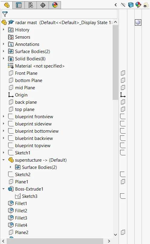
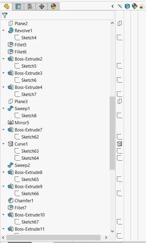
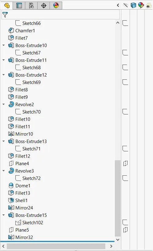
Open blueprint ,Import the superstructure surface where the radar mast has to be created , create new plane with reference to the existing plane and start sketching and with help of sweep, extrude, dome, fillets ,lofted surface create the one side of radar mast and start mirroring it except the bodies which u don’t need to mirror start adding colors by selecting colors in appearance tab ,save as Radar mast
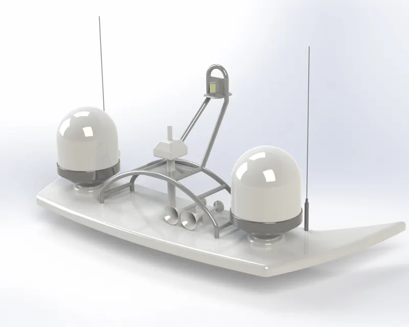
ASSEMBLY:
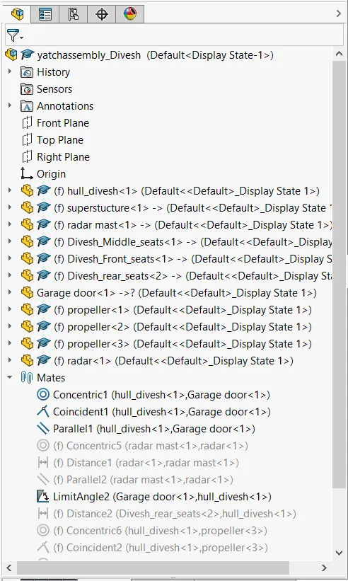
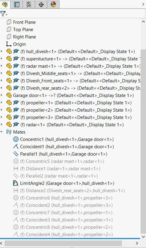
The parts that we’ve created are organised and then assembled in the assembly window by using different mate options like as coincident, concentric, angled, parallel ,limit angel, tangent, width mate etc.
RENDERING:
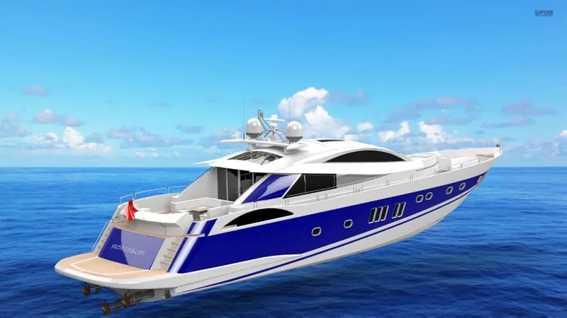
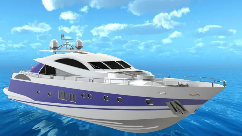
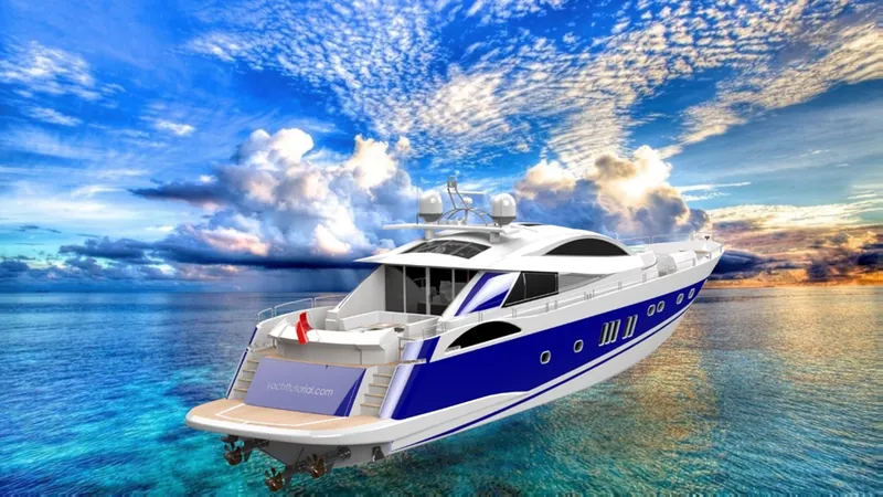
We’ve reach the final step of the yacht to make sure to look the yatch as realistic as possible. Initially I had to make sure my assembled part is in the correct position with appropriate mates being applied in which should be.. Using photo view 360 try different environments based on the project you are looking on. After selection of the environment make sure all the shadows light camera settings are set perfectly .Finally select the resolutions of your render, pixel ,density and perform the final render. We can also use solid works visualize for more realistic renders. The parameters are same but the Solid works gives more options for rendering like HDR background selections, camera settings ,more options in the material selections And save your Rendered image
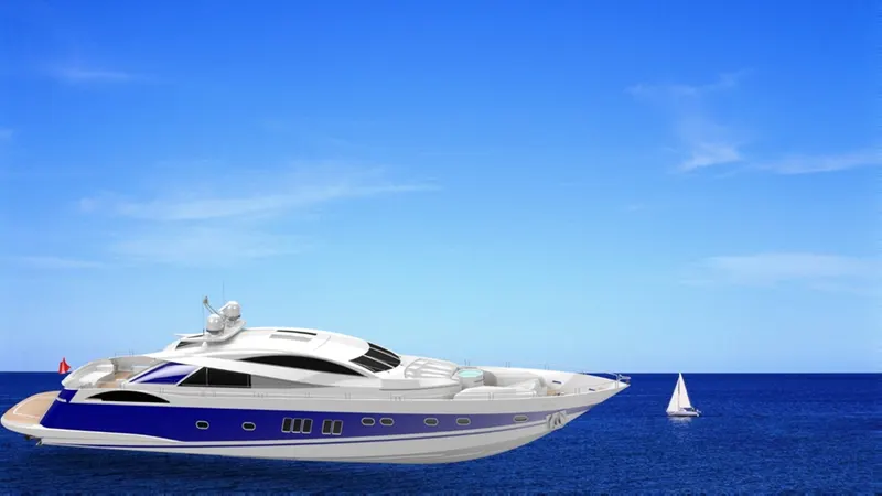
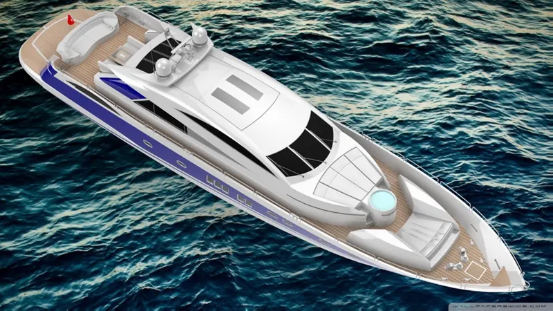
https://drive.google.com/file/d/16nvZN3DNkVi_jF2ypjr9VNnD3DT_nGr7/view?usp=sharing