Photo Realistic Rendering
Designing, Modelling, Assembly and Photo-realistic Rendering of an American Chopper
By :
Divesh Kumar.R
What’s an American chopper ?
A chopper is a type of custom motorcycle that emerged in California in the late 1950s. The chopper is perhaps the most extreme of all custom styles, often using radically modified steering angles and lengthened forks for a stretched-out appearance. They can be built from an original motorcycle that is modified ("chopped") or built from scratch. Some of the characteristic features of choppers are long front ends with extended forks often coupled with an increased rake angle, hardtail frames (frames without rear suspension), very tall "ape hanger" or very short "drag" handlebars, lengthened or stretched frames, and larger than stock front wheels.
Objective:
- I’m an Aspirants who wants to pursue Masters of Science abroad and I find this project will help me in getting admission into a university that I desire
- As a SAE team member from my college I find this course really helpful to convert my ideas into sketches and 3D models. Rendering them and showing photo realistic images will improve my teams sponsorship chances.
- I wanted to learn about the solid modelling and surface modelling tools of the CAD software – SOLIDWORKS since SOLIDWORKS is a dynamic software used primarily in the R&D sectors SOLIDWORKS is widely used in the concept generation stage of production and It gives designers real-time results in product modelling. I want to pursue Design and Modeling as a career. The projects and challenges that I’ve complete in this coursework might help me in job interviews.
Introduction:
- I’ve sketch and build a complete road-ready Harley Davidson bike using SOLIDWORKS.
- In this project I’ve learnt about how to create cut extrudes, revolve cuts, lofts, circular patterns for modelling - Setting up of reference planes - curve generation - projected curve creation understanding how to insert the parts in assembly workspace - Creation of mates - Difference between float and fix parts - Width mates application
- I’ve also learnt how to create photorealistic renderings with real time appearances and views.
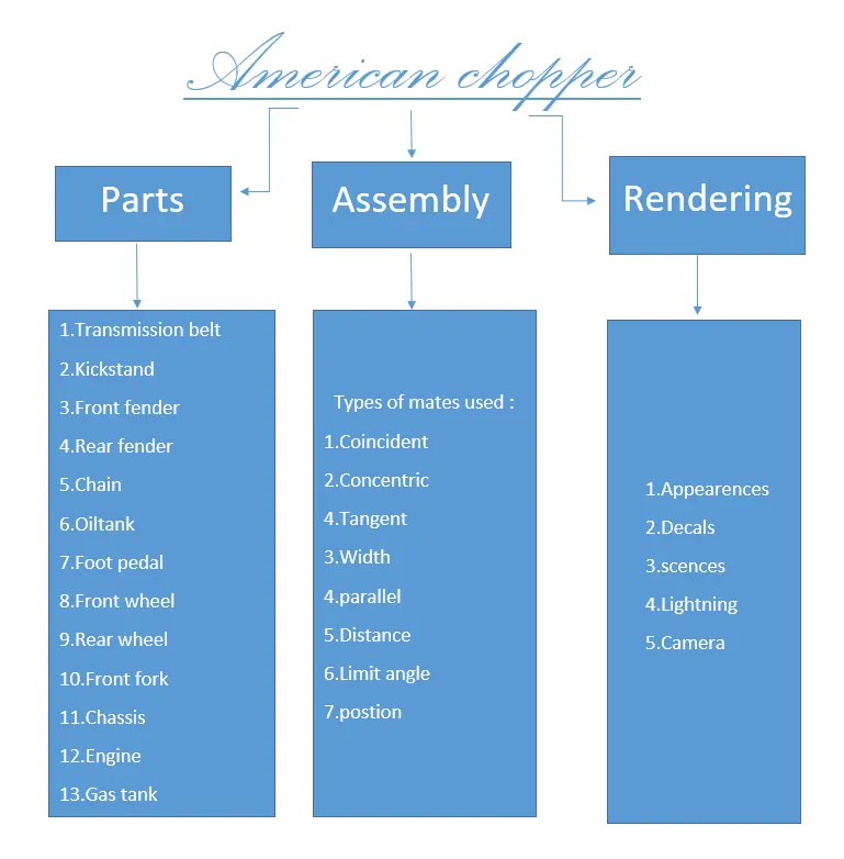
Different parts I had to design to build the American chopper on Solidworks are:
- Transmission belt
- Kickstand
- Front fender
- Rear fender
- Chain
- Oil tank
- Pedal
- Front Wheel with Rim, Calipers and brake rotor
- Rear Wheel With Rim ,Sprocket ,Calipers and brake rotor
- Front Fork With Handle Grips and Head lights
- Chassis
- Engine And Exhaust System
- Gas Tank
Once I’ve completed creating these parts, I’ve to start assembling them with applying appropriate mates , after completing the assembly I started doing photorealistic renderings with real time appearances and views.
Design Methodology:
In this flow chart below I have explained how week by week I’ve designed every components of the American chopper
Features and properties which are used while designing the model of American chopper Bike:
- First of all open a new part with model units set to millimetres.
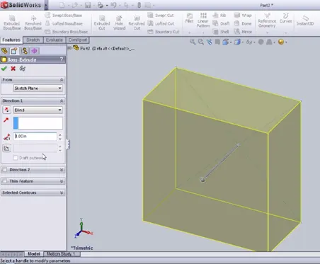
- Boss/Base Extrude Feature:
Is one of the important and very useful tool in Soildworks CAD software to create solid 3D models . It extrudes a sketch or selected sketch contours in one or two directions to create solid feature. That means, if you have closed contour sketch drawing, then you can add materials to that contour and convert it into 3D model via boss/base extrude. However, that is not always the case, which is why the Extrude Boss/Base feature is such a handy tool. Whether you need to extrude something complicated such as up to a feature of another part, or something simple like creating the block, the extrude feature has it all.
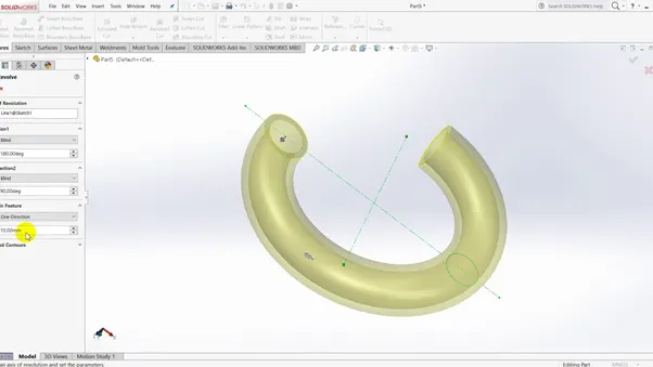
2.Boss/Base Revolve Feature:
Revolved Boss or Base is a SolidWorks feature tool which is used to create solid 3D model around an axis. You can revolve the sketch around an axis to add materials to it. You can access revolved boss/base from both command manager and menubar.
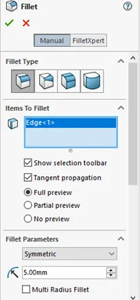
- Fillet:
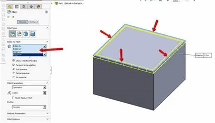
Fillet/Round creates a rounded internal or external face on the part. You can fillet all edges of a face, selected sets of faces, selected edges, or edge loops. There are four types of fillet 1.Constant size fillet 2. Variable size fillet 3. Face fillet 4. Full round fillet . Go to feature then fillet click then show mode type (manual/file expert) fillet type choose any one which is required and then selection window select faces/edges and then fillet radius c
- Extrude Cut:
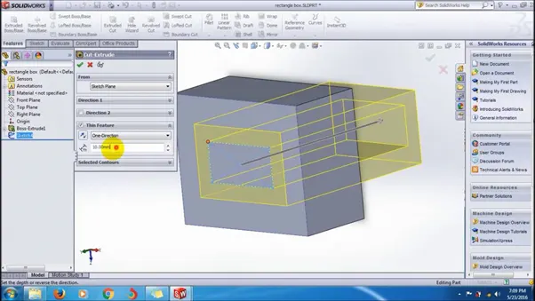
Extrude cut is another cool feature which helps to remove materials from the 3D model. It is just opposite to extrude boss/base feature, because it cuts a sketch profile while extruding. You can cut in both directions and mainly used for creating holes, channels, slots etc .Under the “From” header there is a drop-down list containing a variety of options of where to start the Cut-Extrude from.
- Shell:
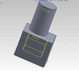
SolidWorks shell tool is mainly used for shelling process, in which the material removed from the inner body of model by keeping small thickness and results a hollow model. Using this tool, you can make either completely closed hollowed model or one face opened type. The shell tool hollows out a part, leaves open the faces you select, and creates thin-walled features on the remaining faces. If you do not select any face on the model, you can shell a solid part, creating a closed, hollow model. . You can also shell a model using multiple thicknesses.
6 . Sweep Bose /Sweep Cut:
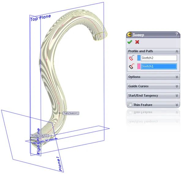
Solidworks Swept boss is one of the useful features which help to sweeps a closed profile through an open or closed path. That means, if you have closed profile (e.g: circle) and have a open or closed path (e.g: two curved line or rectangle); then you can sweeps the closed profile to make your desired part using Swept boss feature.Adding materials by sweeping shape through a designated path. Applying sweep boss we need to be 2sketch usually in two different planes .sweep cut is opposite to the sweep boss.here we can removing materials by sweeping a shape through a designated path . Set the Property Manager options based on the sweep cut feature. To open this Property Manager: Open a part that has either a closed profile sketch and a sketch path, or a part with a sketch line, edge or curve on the model that you can specify as a path.
- Loft Boss/Loft Cut:
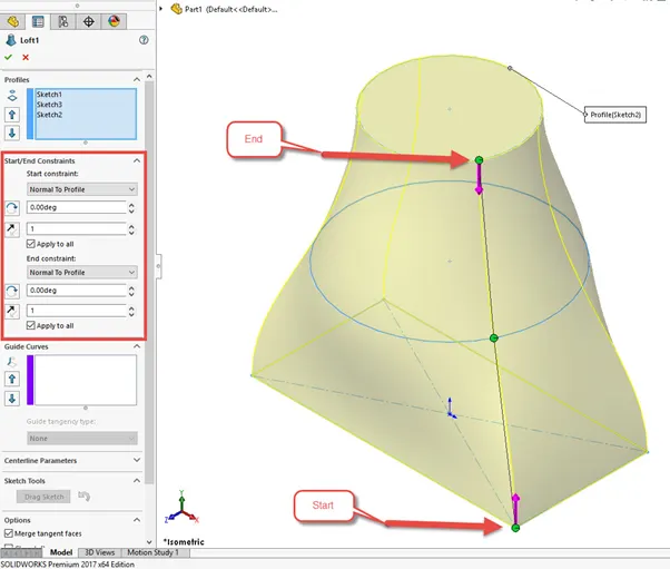
The loft feature is an important tool for (surface) modelling in Solid Works. The loft feature creates a shape by making transitions between multiple profiles and guide curves. This tool is very valuable for modelling complex surfaces loft cut is a solid works features tools which helps to cut or remove material between two or more profile.
- Linear Pattern:
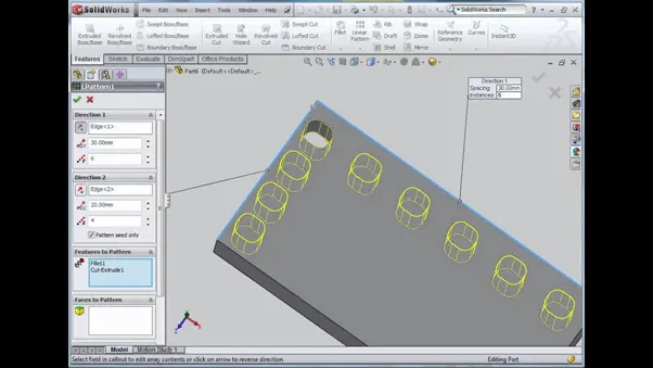
linear patterns to create multiple instances of one or more features that you can space uniformly along one or two linear paths. To create a linear pattern: Create one or more features to replicate. Click Linear Pattern (Features toolbar) or Insert > Pattern/Mirror > Linear Pattern
- Circular pattern:
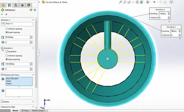
Pattern is based on one feature. Color of the pattern or any faces on any pattern instances have not been changed. The feature colors are not inherited if you pattern or mirror multibody parts. Create one or more features to replicate. Click Circular Pattern (Features toolbar) or Insert > Pattern/Mirror > Circular Pattern
- Mirror:
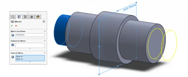
Using the Mirror Part feature lets you create a left hand version of the existing part without having to model it from the ground up. You can use the mirrored part in an assembly without having to use the original part . Creates a copy of a feature, (or multiple features), mirrored about a face or a plane. You can select the feature or you can select the faces that comprise the feature. Bodies to mirror . Select a body in a single model or multibody part to create a mirror entity.
11.Projected Curve:
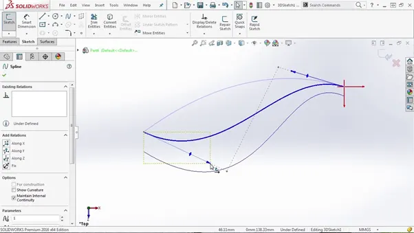
To project a curve: Click Project Curve on the Curves toolbar, or Insert > Curve > Projected. Under Direction of Projection , select a plane, edge, sketch, or face as the direction of the projected curve. Under Projection Faces , select the cylindrical face on the model where you want to project the sketch. A projected curve is typically used either in sweeps and lofts as path or guide curve. There are two types of projected curves: Sketch on Sketch: Use two sketches to make a single curve. Another is sketch on surface.
12. Reference Geometry:
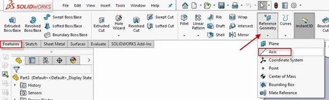
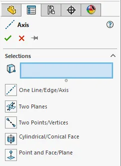
Reference Geometry includes reference planes, axes, coordinate systems, and points. .The Reference Geometry command lives on the Features toolbar, but you can also access it from Insert > Reference Geometry. The Reference Axis Property Manager includes a Selections box where you will define your Reference Axis. The Reference Axis Property Manager includes a Selections box where you will define your Reference Axis. The combinations of these selections that will fully define the Reference Axis are described and depicted below the Selections box.
- COMBINE:
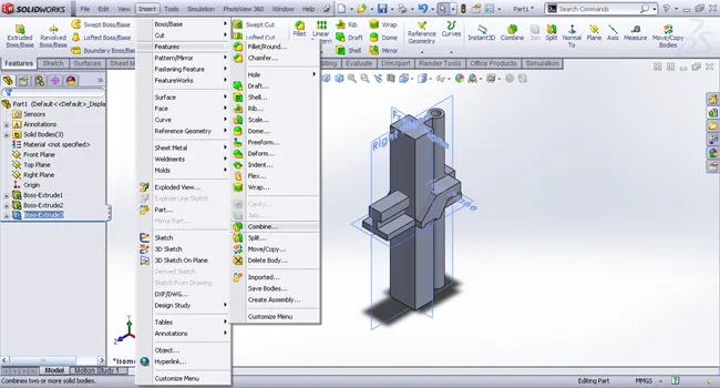
In the PropertyManager, under Operation Type, select Add. For Bodies to Combine, select the bodies to combine. You can select bodies in the graphics area or the Solid Bodies folder in the FeatureManager design tree. Click Show Preview to preview the feature. Click . Search 'Combining Bodies - Add' in the SOLIDWORKS Knowledge BaseThe Combine feature lives under Insert>Features>Combine. The common function allows you to add two bodies together, and keep the area that is common to them. To use this feature, we will select the common button, and then under Bodies to Combine, select the two bodies .
- DOME :
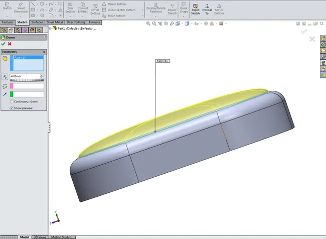
The Parameters in the dome Property Manager include: Faces to Dome. Select one or more planar or non-planar faces. You can apply domes to faces whose centroid lies outside the face. This allows you to apply domes to irregularly shaped contours.
- SPLIT :
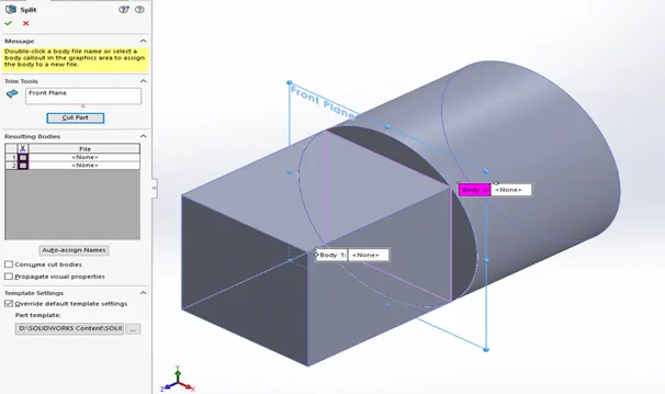
Use the Split feature to create multiple parts from an existing part. You can create separate part files, and form an assembly from the new parts. When you edit split or saved bodies features, you can assign bodies by selecting from a list of derived parts, or by assigning them to other stored part files.
- MATE :
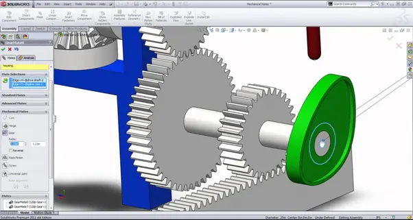
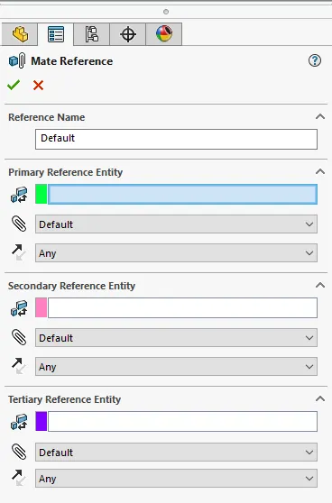
The SOLIDWORKS Mate tool is used for joining parts in an assembly to simulate how they fit and move together. Find out how to mate like a pro in this tutorial… When we create a part in SOLIDWORKS, the position of each body is defined in x , y, z space Mates is the parametric relationship between two or more components used in SolidWorks assembly feature. It helps to add degrees of freedom to your components as per the design. Mates function helps to link the components to assembly file and helps to add particular constrains as per the working of the parts
We’ve seen almost all the Features and properties which have been used while designing the model of American chopper Bike. Now we will discuss all the part component step by step:
1.TRANSMISSION BELT :
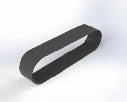
Create a new 2D sketch based on the Mid plane of the Transmission belt and make sure They are in relation to each other and dimensioned correctly. Create an extrude by selecting the sketch loop and then specifying the dimension of the extrude. use fillet tool to give the transmission Belt a smooth finish . select appearance tab specify the material for the Transmission Belt Rubber matte. Save it as transmission belt .the transmission belt is used to transfer power from engine to gear box
2.KICKSTAND:
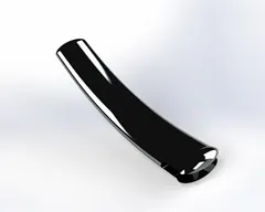
Create a new 2D sketch on the front plane of the kickstand, then use spline and draw the guide way for the loft and then finally add a plane normal to the direction of our spline. After creating a plane create a 2D sketch based on the cross section of the thin portion of the kickstand and create a loft across the guide curve .All the sketch are in relation and dimensioned correctly and the sketch is fully defined. use the dome tool to create a curved shape at both the end sections, and then extrude cut to create a cut near the thick portion of the kickstand so that it can be attached to the pivot. after that split feature used .To create pivot point to attach to the frame we will create cylindrical section near cut out of the kickstand. Fillet the edges for a smooth finish and in the appearances select chrome plate . Save the part as kickstand. A kickstand is a device on a bicycle or motorcycle that allows the bike to be kept upright without leaning against another object or the aid of a person. A kickstand is usually a piece of metal that flips down from the frame and makes contact with the ground.
FRONT FENDER :
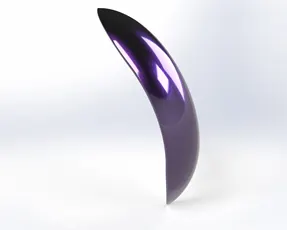
Create a2D sketch on the mid plane of the front Fender and then use the revolve tools by specifying the angle of revolving in both the dimensions. Sketch the design of the cut out portions at both the end section of the front fender. Fillet the edge of the front fender .using appearances under painted car Siena colour .looking very stylist . Save the part as Front Fender. A front fender will help protect your feet and ankles from spray if you're riding in the rain or even through a puddle.
4. REAR FENDER:
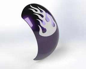
Create a2D sketch based on the Mid plane of the Rear Fender and then use the revolve tools by specifying the angle of revolving in both the dimensions . Sketch the design of the cut out portions at both the end section of the Rear fender.Fillet the edge of the Rear fender .using appearances under painted car Siena colour .looking very stylist . Save the part as Rear Fender. A rear fender are what will keep you from having a skunk stripe on your backside if you ride in the rain
- CHAIN:
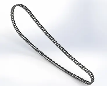
Create a 2d sketch with the help of line and arc tools making the outer edges of the chain link. Create the front and back link of a chain and saved as a block diagram to use continuously with the relation of concentric to joint of the path . Determine how much block diagram needed to complete the curve by using our mouse middle bottom scrolling until the entire loop completed . After that mirror the face of the links to the pins in the block diagram with respect to the mid plan. A fine finished chrome plate metal is used as the appearance of the linked part. Save the the chain . Chains are basically used to transmit power ,here the chain is used to transmit power from gear box to the chain
- OIL TANK:
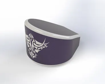
Create a2D Sketch on the Top plane and extruded . Again create a sketch on the mid plane and extruded . After that Extruded The Sketch Combine Feature used and combine both the extrude together. And another feature is used that is shell feature is used to make the part hollow and edges are fillet. In the appearance tap use same as Siena colour In the body .Fillet edges are painted as White paint. Save the part . Oil tank in a bike is used to store engine oil
- PEDAL:
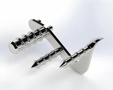
Create a 2D sketch based on Front plane the base of the pedal ,and then extruded boss is created with dimensional circular hole for the foot rest. And pins extruded again .Now create a sketch on the top plane and revolved . And Now applied Dome Feature and filleted the edges. After that the front and rear extruded cylindrical part chamfered . circular pattern is extruded on each of the front facing extrudes which are then arranged using linear patter. And filleted edges.save the part. Pedal Helps to Rest Feet Constantly While Riding
- FRONT WHEEL:
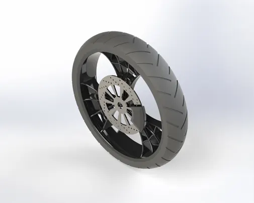
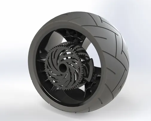
Create a 2D sketch on front plane . Then using revolved feature for making tires . After that using the Extrude Boss Feature for making or create the Rims Calipers ,Rotor ,Sprocket.Now we using the Extrude Cut feature for remove the additional materials from the extruded rims for the spider webbed design. And also for cut out from the sprocket rim rotor. After that we using Cut Revolve to cut out the side sections. Then Using circular pattern in the sprocket, Rotor, Rim Tire Grip Design. Appearances uses to specify the materials of various part. Save the part.front wheel is used to change the direction of the bike in which it is travelling in
- Rear Wheel :
The designing of both the wheels are similar the differences is in the size of the wheel .Create a 2D sketch on front plane . Then using revolved feature for making tires . After that using the Extrude Boss Feature for making or create the Rims Calipers ,Rotor ,Sprocket viz. Now we using the Extrude Cut feature for remove the additional materials from the extruded rims for the spider webbed design . And also for cut out from the sprocket and rotor. After that we using Cut revolve to cut the side section from the extruded rims for the spider Webbed Design . After that we using circular pattern in the sprocket, Rotor, Rims Tire Grip Design. Appearances uses to specify the materials of various part. Save the part. Rear wheel is used to utilize the power provided by the engine and to move the vehicle
- FRONT FORK:
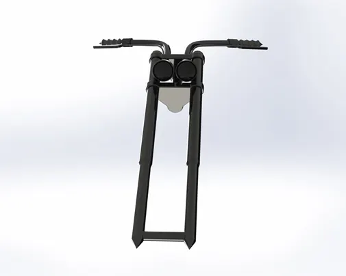
To Create a 2D sketch On a Front plane .And by using Revolved Boss feature to create fork tube . Again create a sketch and create handle grip by Revolve boss Feature. In this Revolve Boss Feature We create Head light .We using Extrude Boss to create the Triple clamps ,Breaks viz. In this Extrude Cut Feature we create circular cutouts for the triple clamps. And use another feature that is dome to create the dome shape of the headlight. To create the two portions of the triple clamps by using linear pattern feature. we create the complex shape of the Bike Handle bars &the Break Wires ,Projected curve was used to create the path for the sweep command and then the sweep too we used from the feature tab to complete the Bike Handles .the same procedure was used to design the break wires. Appearance to specify the materials of various part. Save the part. A bike’s front fork is the part of a bike that holds the front wheel. A fork typically consists of two blades which are joined at the top by a fork crown. The crown is often at the front. ... The steerer tube of the fork interfaces with the frame via bearings called a headset mounted in the head tube.
- CHASSIS:
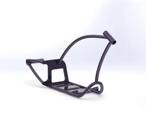
Before Creating Sketch We also Rename the Plane For Better Understanding . Now Create a 2D Sketches on the Mid plane Chassis. The Sketch Based On the Reference blue Print Of the American Chopper. Extrude feature was used to create plate sections of the chassis. And then used Sweep feature to design the chassis cylindrical structures of the chassis. Projected curve features was used to create the sweep paths of the complex geometry. Then using Extruded cut Feature to cut the Extra portions of the Extruded bodies. After that we using Revolve cut functions to create the cylindrical geometries and to cut out unwanted portions from the revolved parts . some other features used included Mirror ,Dome, Fillet , Chamfer. In Appearances Tab we use Siena color. Save the part. A bike’s chassis or frame forms its skeleton. All the components of a bike, like the suspension, wheels, fuel tank, seats, handlebars etc, are attached to this base structure which lends a motorcycle its strength and ability to handle well.
- ENGINE :
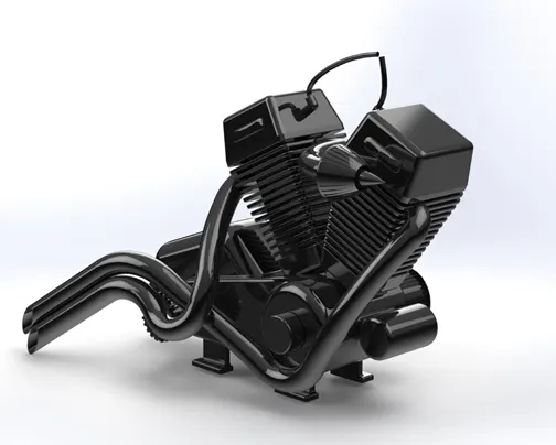
Initially ,2D sketchs were drawn through the reference of blueprint of chopper image and the extruded feature is used to create each part of the engine like a sprocket, engine cylinder ,engine exhaust system.Chamfer feature ids used to create the tapering design of the two engine cylinder.The sweep ,projected curve feature is used to create the complex geometry path for the sweep, split ,extrude cut, revolve feature were used to create the air Filter and the Exhaust manifold.The linear pattern feature and circular pattern werte used to design the cutout sections of the row of fins on the engine cylinder and the the circular cutouts from the sprocket respectively. Some other feature were used like as mirror, dome ,fillet .Save the part. Engine is the heart of your bike it generates power to run the bike
- GAS TANK :
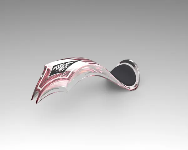
To create a2D sketches with Based on the Blueprint chopper image. Creating a 2D spline sketch its Surface sweep Feature was used for making the outer layer of the Gas tank.The split line was usd to remove the unwanted part by designing the shape to be cut.Surface Knit feature were used and then Combine the Surfaces of the gas tank.And then using a surface loft is created as the front face of the tank now with the help of boundary sweep feature the front face and the side face are joined. A sketch is drawn at the face of the gas tank to cut the u section all the sharp ends are then filleted a shell is created at the end to make it hollow. Other tools used like cut sweep In the Appearances Tab we were used siena color .and for seat material we used Grey cotton .Save the Part. Gas tank is used to store the fuel which is used by the engine to generate power
ASSEMBLY:
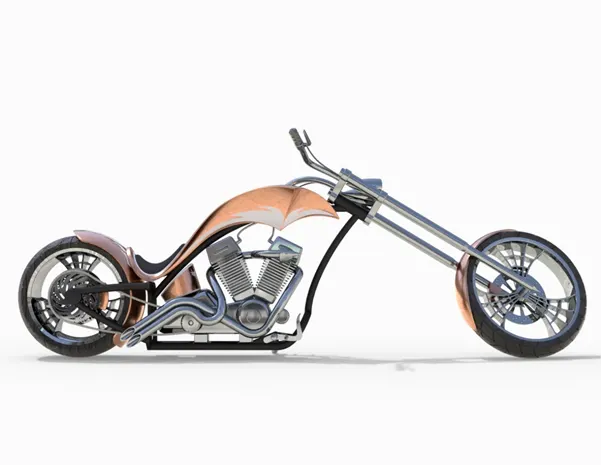
The parts that we’ve created are organised and then assembled in the assembly window by using different mate options like as coincident, concentric, angled, parallel ,limit angel, tangent, width mate etc.
RENDERING:
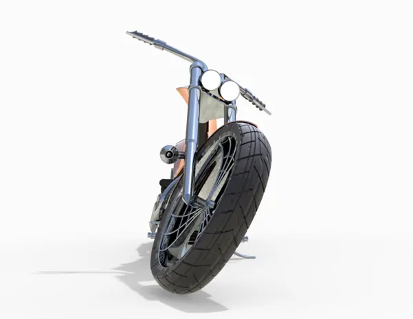
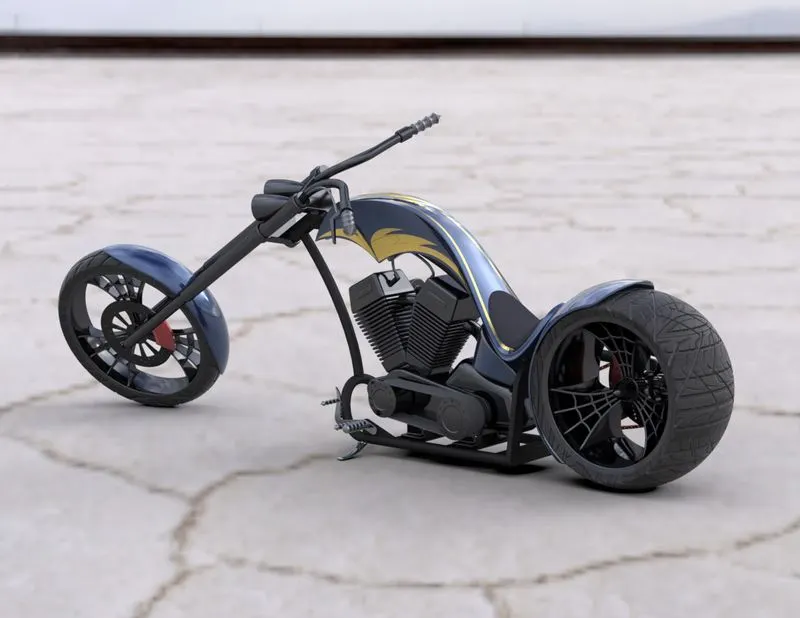
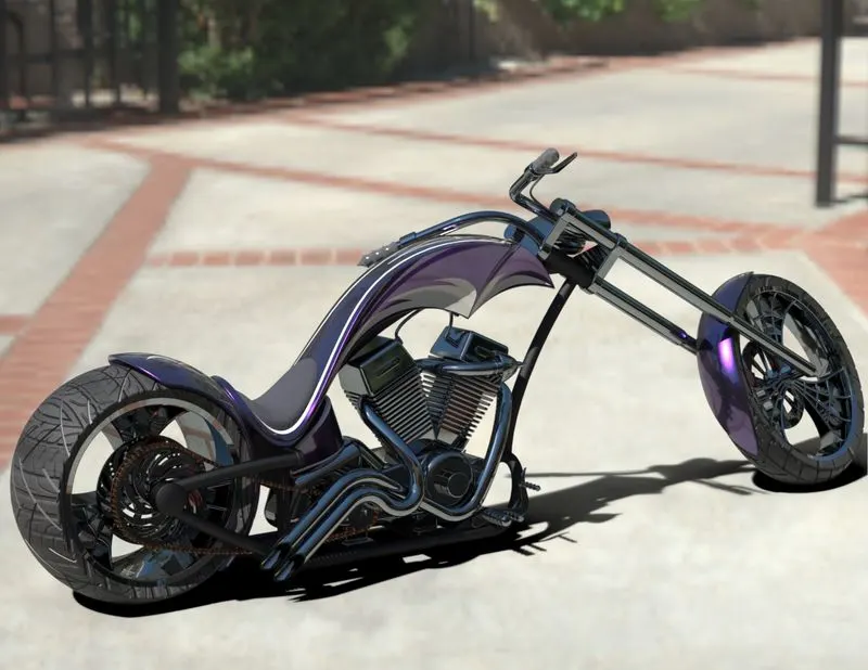
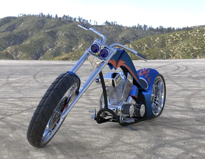
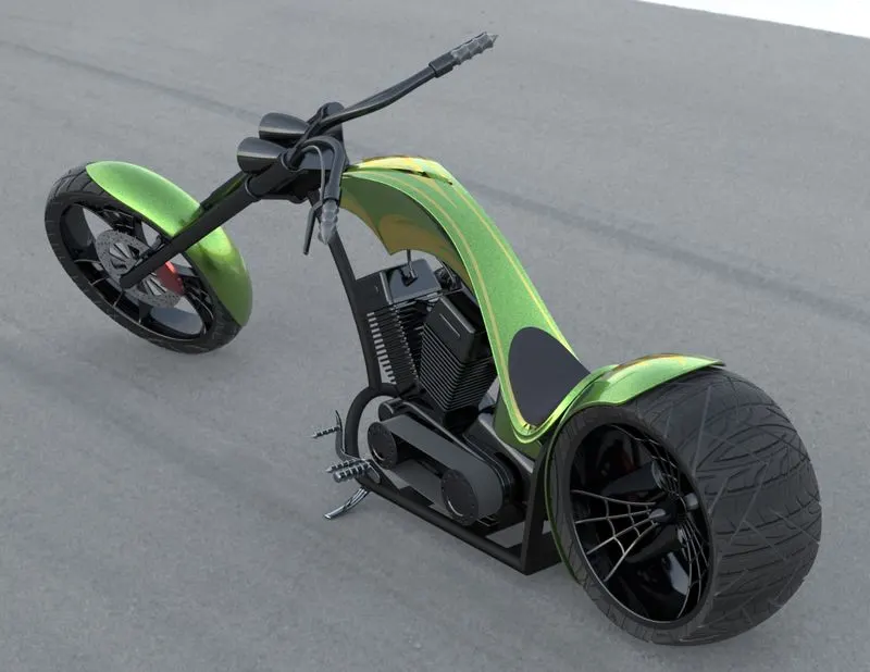
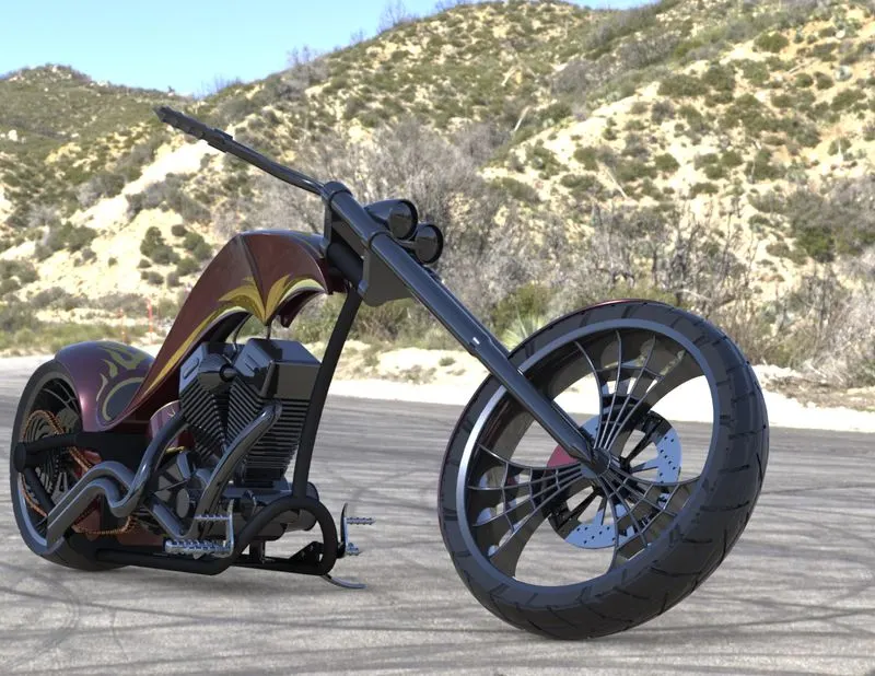
We’ve reach the final step of the bike to make sure to look the bike as realistic as possible. Initially I had to make sure my assembled part is in the correct position with appropriate mates being applied in which should be. In this case we want to the chopper to learn on the stand to make sure the chopper is slightly tilted towards the stand so that it gives a more realistic look. Using photo view 360 try different environments based on the project you are looking on. After selection of the environment make sure all the shadows light camera settings are set perfectly .Finally select the resolutions of your render, pixel ,density and perform the final render. We can also use solid works visualize for more realistic renders. The parameters are same but the Solid works gives more options for rendering like HDR background selections, camera settings ,more options in the material selections And save your Rendered image
https://drive.google.com/file/d/1ts-iin7I4dAY1VDDLyScOQnD-DaXjF-P/view?usp=sharing