Radar Mast & Final Assembly of Yacht
1. radar mast:
2. yacht assemble:
Modeling of yacht:
Objective:
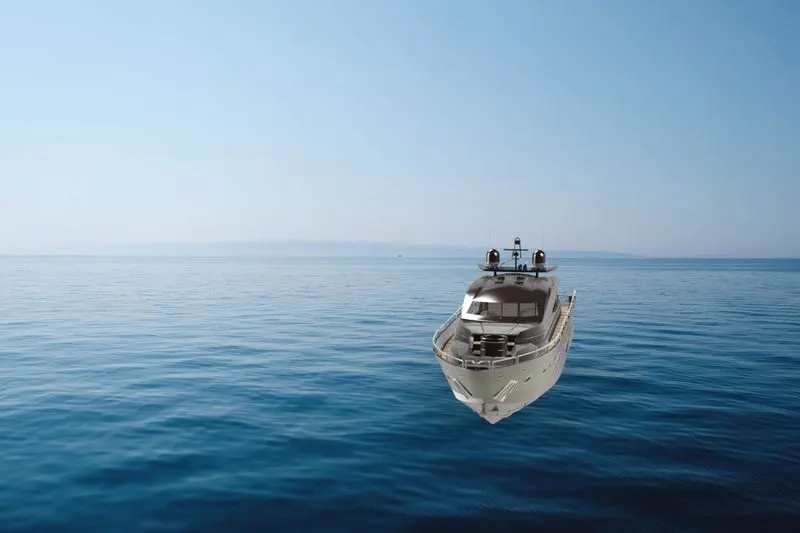
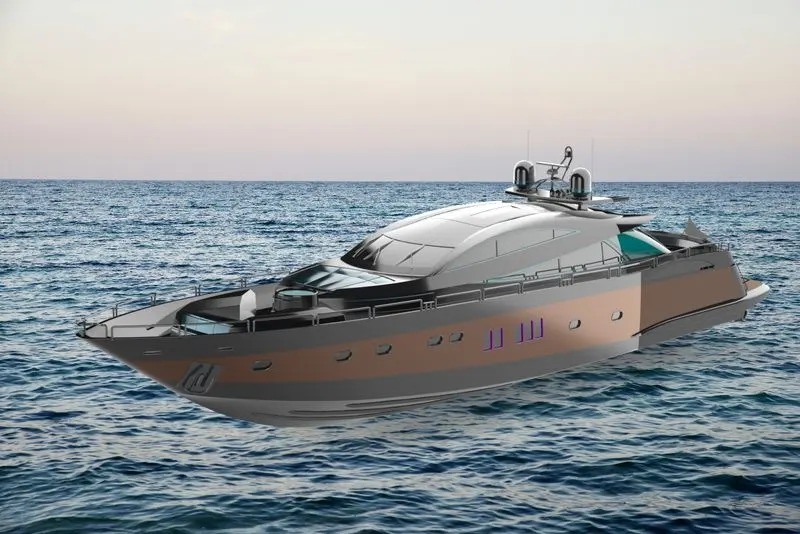
To creates a 3d model of a yacht using Solidworks and render it with solidworks visualize.
Introduction:
A yacht is a sail or power vessel used for pleasure, cruising, or racing.
Design considerations for a cruising yacht include seaworthiness, performance, sea kindliness, and cost of construcion, as follows:
Sea kindliness is as indicator of steering ease, directional stability and quelling of motion induced by wind and waves.
Multihull offer tradeoffs as cruising sailboats, compared with monohulls. They may be catamarans or trimarans. They rely on form stability-having separate hulls far apart-for their resistance to capsize. Their advantages include grater stability. spee, (for catamarans) living space, and shallower draft. Their drawbacks include: grater expenses, grater wind age, more difficult tacking under sail, less load capacity, and more manevering room required because of their broad beam. They come with a variety of sleeping accomodations and (for catamarans) bridge-deck configurations.
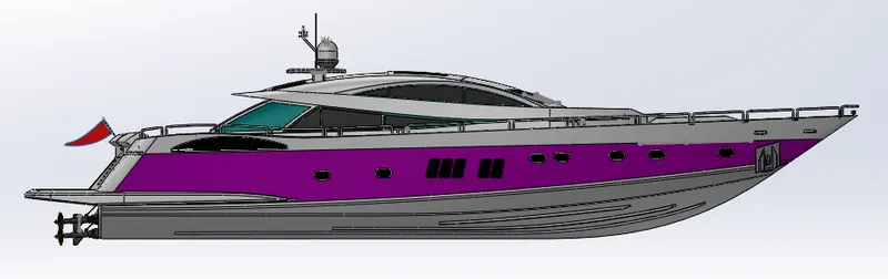
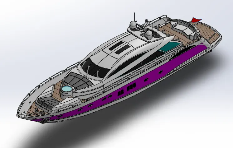
Design of yacht involves creating individual parts and assembling them with respect to their proper constrains and mates.
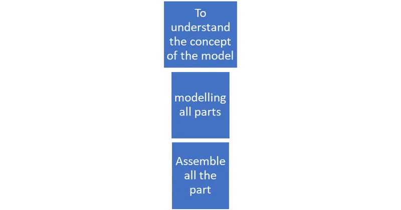
The modelling of yacht involves 3 stages:
- Modelling of individual parts
- Assembling of the parts
- Rendering the components
The yacht consists of the following parts:
- Hull
- Radar mast
- Front, middle and rear seat
- Garage door
- Superstructure
- Propeller
- Radar
During the modelling of the yacht parts, reference planes are created if it is necessary, and since it is cosmetic model tolerance is not considered deliberately.
Design methodology:
The design process will help us to design the product considering the impact on other stages.
Design approach:
- Design approaches which means how we are going to design a product a pre-step for designing a product.
- There are two different types are out there when we came into solid works top-down methodology and bottom-up methodology.
Design approaches has two types:
- top down
- bottom up
Top-Down:
- The top-down method is a convenient one over compared to the bottom-up method.
- Because the hole design of a product will be designed by the assembly template itself.
Bottom-up:
- In the bottom-up method, each part are designed separtely once all of the parts are done with designed then all the parts are performed in the assembly different parts of the product, in the case a yacht.
- Different types of mates are used to assemble parts.
1. Hull:
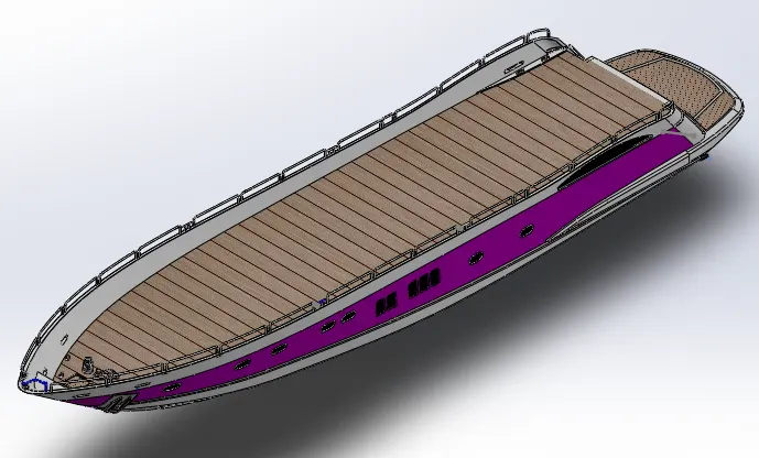
A hull is the watertight body of a ship or boat. The hull may open at the top and it may be fully or partially covered with a deck. A top the deck may be a deckhouse and other superstructures, such as a funnel, derrick, or mast. The line where the hull meets the water surface is called the waterline.Hull is the base of the yacht and it is symmetric model. Therefore it it enough to model one half and other side could be mirrored.
The design of hull involves preparation of outer shell surface and the deck surface. Initially the hull designed as a surface modelling and then convert into the solid because hull consists of lot of critical curve surface.
Command used:
- Curves projection
- 3D sketch
- Surface extrude
- Surface loft
- Sweep
- Surface knit
- helix/spiral
- convert entities
- Surface split
curves projection: It is one of the option in solidworks tool which gives us the output cure for the two curves/lines drawn on different planes, this is the intersection path where the two extruded surfaces meet.
3D sketch: it is very handy tool to draw any line or curve in space as it is confined to the axis helps to join the projected curves and work on different axis to create geometrical planes.
Surface extrude: It is used to form the surface bodies where the thickness is line thick.
Surface loft:Loft is the option used to prepare very difficult surfaces formed with the help of 4 different curves drawn on different planes. It involves two profiles curves and one or more guide curves.
Surface knit: it helps to eliminate the minor gaps exist between the two surfaces and join them together as like a single surface. This option works only for surfaces not for solid bodies.
Convert entities: It is available in 2d sketching tab which convert edges of the 3d object to the line projected on tot the surface.
Sweep: It helps to produce solid tube along the guided curve/line path.
The rope for the anchors is prepared using the option helix/spiral.
Helix/spiral: It is used to create any spring it screw treads as this option contains pitch or height and revolution which describes how many rings with gap between them.
Surface Split: It consume cut body and the removed body is saved as a different part in the name of garage door.
2. Radar mast:
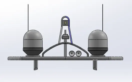
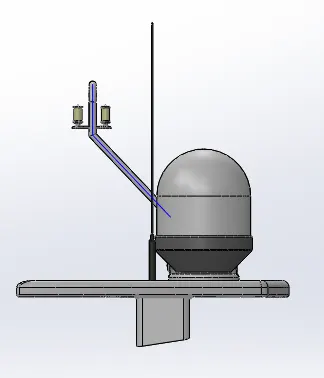
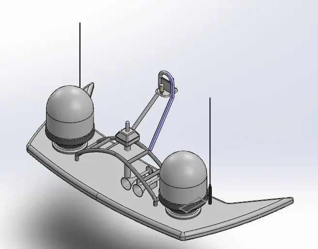
Marine radars are X band or S band radars on ships, used to detect other ships and land obstacles, to provide bearing and distance for collision avoidance and navigation at sea. They are electronic navigation component for safety at sea and near the shore. Captains need to be able to maneuver their ships within feet in the worst of condition and to be able to manuever their ships within feet in the worst condition and to be able to navigate"blind". when there is no visibility at night or due to bad weather. In addition to vessel-based marine radars, in port or in harbor, shore-based vessel traffic service radar system are used by harbourmasters and coast guard to monitor and regulate ship movement in busy waters.
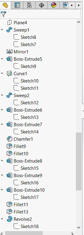
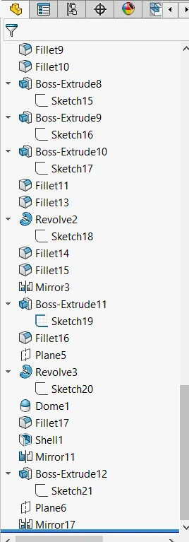
Here Radar is rotating stick which sweeps the incoming microwave signals and radar mast contains the system to produce the outgoing signals using the antenna. Design of this component involves base creations initially in 2d sketcher and that is being extruded in the features tab. The lobes on two sides as shown in pictures is drawn on a plane which is created with reference to midplane offset at a required distances and using revolve tools solid with reference to mid plane offset at a required distance and using revolve tool solid cyclindrical object is formed on the base.
Command used :
- Revolves
- shell
- Extrude
Revolves: This tools requires a closed sketch with the central axis which helps to form the cyclindrical object with reference to central axis.
Shell: This tool helps to create the shell to the solid body which prompts to enter the thickness and reform the solid object into shell type object with the wall thickness as provided.
Extrude: To use convert the 2d sketch into 3d model by making a solid within the closed contour.
3. Front, middle and rear seats:
These front, middle and rear seats are the accessories of the yacht for resting and sitting. These three seats are modelled for yacht based on the deck surface imported from hell. Front and rear seat modelled in a similiar fashion like both are modelled intitally as surface and then convert into solid. All the three seats are placed on the top of the hull.
Here the both front and rear seats are symmetric structure so it enough to model one half so that the other hald could be mirrored.
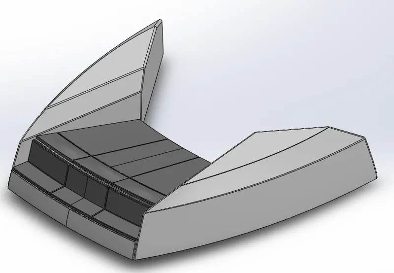
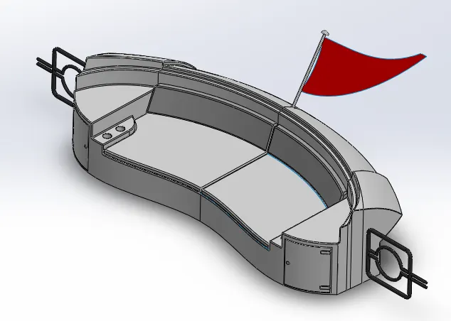
In the middle seats unlike other two seats, it is modelled fully on solid modelling.
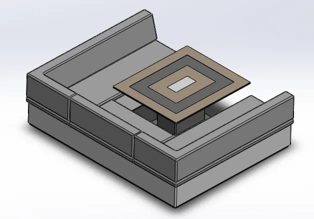
Command used:
- Sweep surface
- Trim surface
- Knit surface
- Surface extrude
- fillet
- chamfer
- mirror
- cut extrude
Sweep surface: It is used to build a model as per the origin and the curve like the curved objects with zero thickness.
Trim surface: It is used to remove surface from one surface with the use of other face or sketch.
Knit surface: It is used to merge all other surface that we are created.
Fillet: To smoothening the edges of sharp corner of object
Chamfer: It reducing sharp edges by making some angles.
Mirror: To reflect the object for one side of axis/plane/face to other side.
Cut extrude: To remove material from the selected contour.
4. Garage door:
Garage is part that is extracted from the hull structure rear part using split entities option and is been saved using different file name and it is edited to fit in the hull a cover or door to the garage space created for storing or equipment or vehicles.
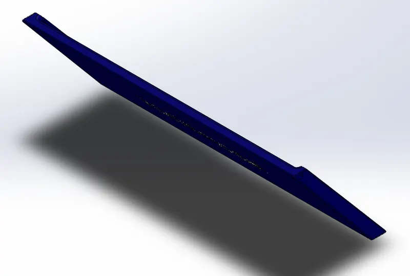
Command used:
- Cut extrude
- extrude fillet
- chamfer
- fillet
- mirror
5. Superstructure:
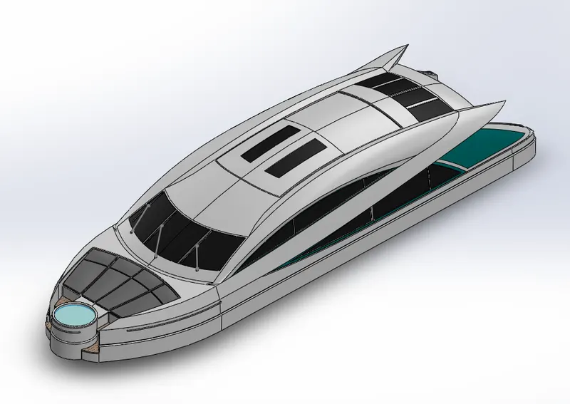
The most complicated part of the whole yacht design is its superstructure which sits on top of the deck surfaces.
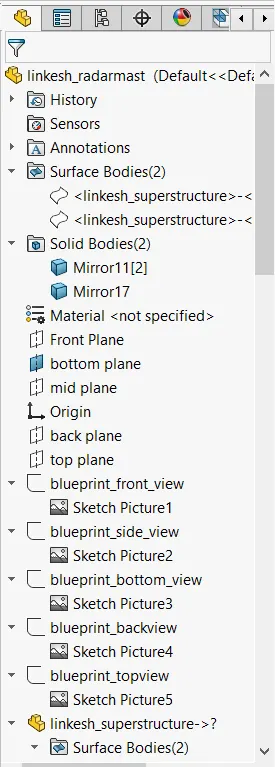
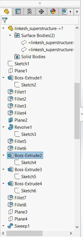
This superstructure also designed with the help of the imported blue print top, front, back, bottom and side views as shown in below picture.
Initially the wall of the super structure is created by drawing a line on the bottom plane along with the curvature using spline option and making it constrained using proper dimension and being surface extruded in the feature manager tab.
After finish the model convert surface model into solid before that we have to merge all the surface that we are created by usind knit surface for that there is should be no gap between the surface of the superstructure.
Command used:
- 3D sketch
- loft surface
- Sweep surface
- Trim surface
- Ruled surface
- Knit surface
- Fill surface
- Cut extrude
- Revolve
- Dome
- Shell
- Fillet
Ruled surface: It is used to obtain the extrude surface perpendicular do the plane of reference and the added advantage of ruled surface is that the surface can tilted with and angle as prompted in the tool along with the length.
Dome: It is used to create a smooth finish like cap at the end of the extended object.
Surface fill: It is also form the surface where there is no surface by using sourrounding edges of surface, selecting by in order.
6. Propeller:
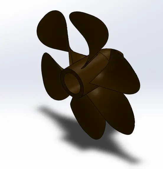
A propeller is a device with a rotating hub and radiating blades that are set at a pitch to form a helical spiral, that, when rotated, performs an action which is similiar to Archimedes' screw. It transform rotational power into linear thrust by acting upon a working fluid, such a water or air.
For designing the propeller the main hub is created by simple sketch line and spline drawn on the front plane and extruded using the revolve option around the centre line. The wings are twisted parts created by sketching the two different rectangles on two different surfaces and formed into solid using loft option. The shape of the wings are obtained fillet applied at two edges on the top side. For inserting the shaft the hole is created by sketching the circle on the hub back end and material is removed using extrude cut option. color is applied to the propeller for appearances as shown in figure.
Command used:
- Revolve
- Loft base
- Fillet
- Cut extrude
- Pattern
Pattern: This feature used to create multiple the selected part/face/sketch with reference of any axis/plane with direction.
7. Radar:
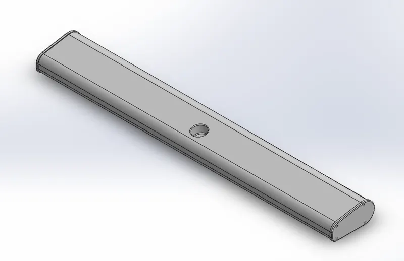
Radar is a device used for detecting objects. It is a very important device in any yacht /ship. It is mated with a part a part called radar mast and placed on the topmost part of the yacht. It is modelled only in solid modelling. It is a symmetric model so the other half is mirrored.
Command used:
- Mirror
- text
- Cut extrude
Text: It is used to project a letter or number on the object like wraping purpose.
Assembly:
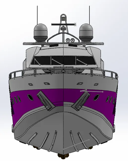
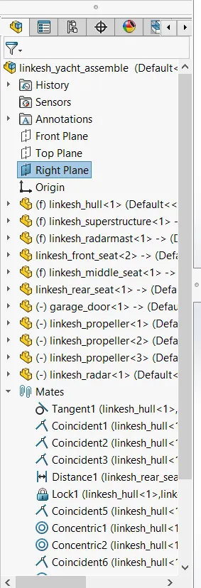
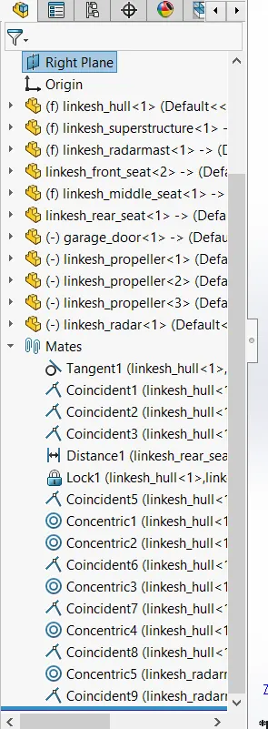
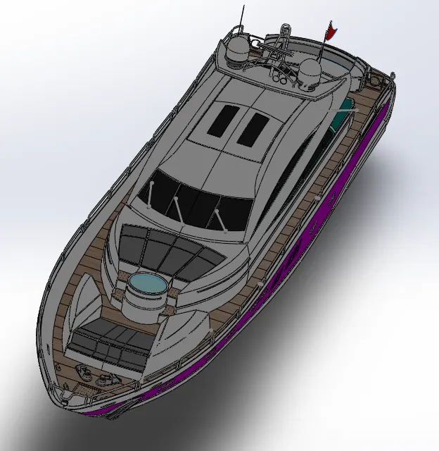
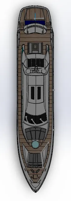
All the components are imported into the assembly workbench are according to the tree chart and applied mates to fix their position with respect to the fixed body or object.
The commonly used constrains are coincident, offset, concentricity etc.
Rendering:
Rendering or image synthesis is the process of generating a photorealistic or non-photorealistic image from a 2d or 3d model by means of computer program. The resulting images is referred to as the render.
In solidworks rendering is done in solidworks visualizer. In this we need to import required solidworks part/assembly/assembly components and by backplate we get the rendered output image as a shown below.
Conclusion:
Thus the required yacht is modelled using solidworks and rendered successfully.