Photo Realistic Rendering
AMERICAN CHOPPER
Objective:
- The objective of this project is used to create a model of different parts of american chopper using solidworks.
- To assemble the various parts modeled for the chopper.
- To create a photorealistic model of the chopper by render the model using solidworks visualize.
Introduction:
American chopper is a type of custom motorcycle. The chopper is perhaps the most extreme of all custom styles, often using radically modified steering angles and lengthened forks for a stretched out appearance. Some of the characteristic features of chopper are long front end with extended forks often coupled with an increased rake angle, hardtail frames (frames without rear suspension), very tall "ape hanger" or very short "drag" handlesbars, lengthened or stretched frames, and larger than stock front wheels.
The first chopper were built in America and tended to be based on harley-davidson motorcycles. Rather than being primarily performance oriented modification, chopper are more about achieving a certain look. So the purpose of this project is to create an aesthetic model of chopper using Solidworks and solidworks visualize.
Design methodology:
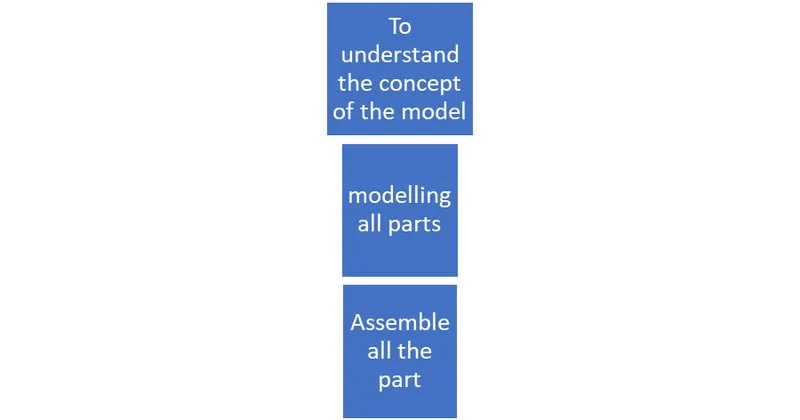
The design process will help us to design the product considering the impact on other stages.
Design approach:
- Design approaches which means how we are going to design a product a pre-step for designing a product.
- There are two different types are out there when we came into solid works top-down methodology and bottom-up methodology.
Design approaches has two types:
- top down
- bottom up
Top-Down:
The top-down method is a convenient one over compared to the bottom-up method.
Because the hole design of a product will be designed by the assembly template itself.
Bottom-up:
- In the bottom-up method, each part are designed separtely once all of the parts are done with designed then all the parts are performed in the assembly different parts of the product, in the case a chopper.
- Different types of mates are used to assemble parts.
Part modelling:
- The following parts of the chopper are modeled in solidworks and assembled together.
- Transmission belt
- Front Stand
- Rear Fender
- Kick Stand
- Chain
- Gas tank
- Pedal
- Front Wheel
- Rear Wheel
- Front Fork
- Chassis
- Engine
- Oil tank
1.Transmission belt:
- The Transmission Belt in the chopper is used to transmit the power from the Engine to the Gearbox.
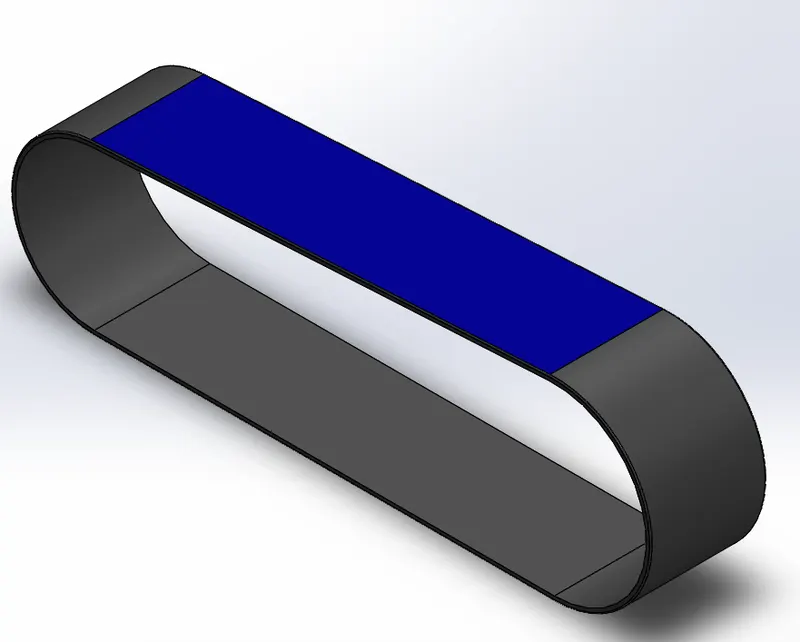
Features used to create Transmission belt:
- Sketch
- Offset
- Extrude
- Fillet
- Appearance
Sketch:
Sketch is the two dimensional representation of the model with respect to the plane/view from the outside of the model. These are known as Entities in solidwork. The following are the entities available in solidworks line, Arc, Circles, Rectangles.
Offset:
Offset one or more sketch entities, selected model edges, or model faces by a specified distance. For examples, you can offset sketch entities such as splines or arcs, sets of model edges, loops, and so on. You can offset finite lines, arcs, and splines.
Extrude:
Extrude is a types of features available in solidworks to convert a 2d sketch into the 3d model.
Fillet:
Fillet/Round creates a rounded internal or external face on the part. You can fillet all edges of a face, selected set of faces, selected edges, or loops.
2. Front Fender:
- Front Fender used to prevent the dirt and water from the rotating wheel.
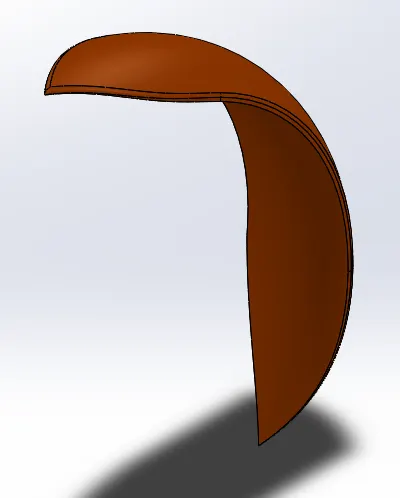
Command used in Front Fender:
- Sketch
- Revolved boss
- Split
Revolved boss:
The command used to revolve the sketch in 360 deg.
Split:
Split command is used to split the extruded part using a defined sketch.
3. Rear fender:
Rear fender is also like front fender in purpose of prevent dirt and water.
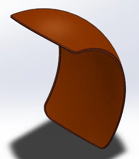
Command used in Rear Fender:
- Sketch
- Revolved boss
- split
4. Kick stand:
Kick stand is used to hold the bike in a leaning position.
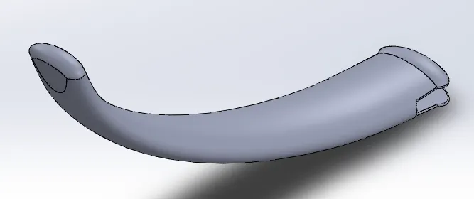
Command used in kick stand:
- Sketch
- Sweep
- Boss extrude
- Cut extrude
Sweep:
Sweep command is used to draw a part by the sketch profile guided by the defined path.
Cut Extrude:
Cut extrude command is used to cut the extruded part with defined sketch.
5. Transmission chain:
Chain link is used to transmit the power from gear box to the rear wheel.
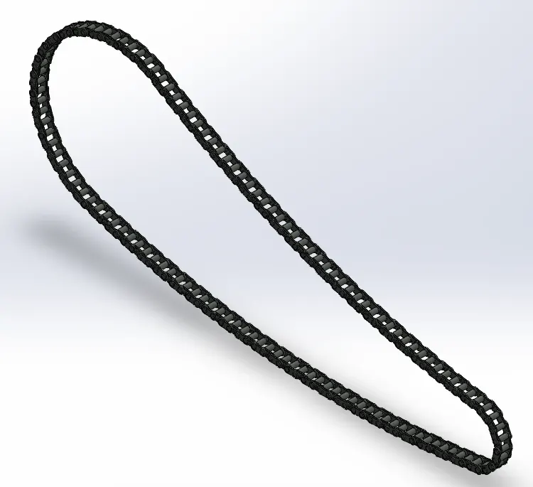
Command used in chain link:
- Sketch
- Block
- Boss Extrude
- Curve pattern
Block:
Block command is just a sketch , which can save the sketch and used multi times in the drawing.
Curve pattern:
Curve pattern is used to pattern the extrude parts with the curved sketches as a guide path.
6. gas tank:
Gas tank is used to store the gasoline which is used to power the engine.
Commands used in fuel tank:
- Sketch
- surface loft
- surface trim
- surface fill
Surface trim:
Surface trim is used to trim or delete the unwanted surface.
Surface fill:
Surface fill is used to fill the surface in closed loop of surface or define sketch.
Pedal:
Pedal is used for resting bike riders foot while driving.
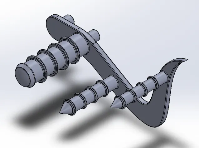
Commands used for pedal:
- Sketch
- Boss extrude
- linear pattern
- Fillet
- Chamfer
Linear pattern:
Linear pattern is used to pattern the part in a given direction.
Fillet:
Fillet command is used to make round the corner face.
Chamfer:
Chamfer command is used to make chamfer of the corner of the part with given degree and distance.
Front and Rear wheel:
Wheel is rotating part which is used to move the bike. It has to have some external force to move.
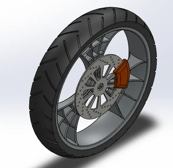
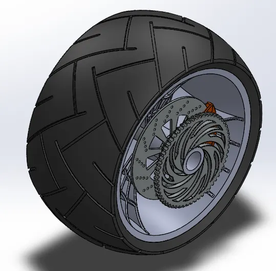
Command used in wheels:
- Sketch
- Revolve boss/base
- Revolve cut
- Circular pattern
Revolve cut:
Revolve cut command is used to cut the parts by revolving the sketch 360 deg.
Circular pattern:
Circular pattern is used to pattern the sketch or parts in a circular path with reference to the axis.
Front Fork:
Front fork is used as a handle of the bike which is used to turn the bike in a required direction.
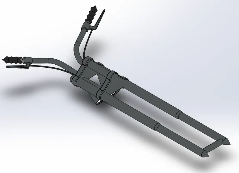
Command used in front fork:
- Sketch
- Mirror
- Boss extrude
- Sweep
- Revolve
- Project curve
Mirror:
Mirror command is used to duplicate the parts with reference to the plane, face or edges.
Projected curve:
The project curve is used to combine the two sketchs or curve.
Engine:
Engine is the main part of the bike. Its used to to generate the power to move the vehicle.
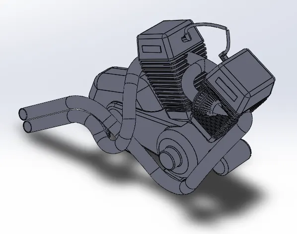
Commands used in engine:
- Sketch
- Projected curve
- Sweep
- Boss extrude
- Mirror
- Linear pattern
Chassis:
Chassis is the frame of the bike which hold every parts of the bike and designed in the manner to distribute the load equally.
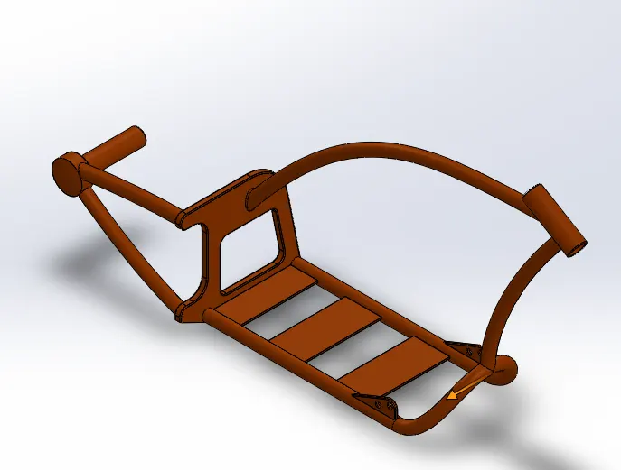
Commands used in chassis:
- Sketch
- Project curve
- Extrude
- Fillet
- split
- cut extrude
- sweep
Oil tank:
Oil tank used to store a oil for reducing heat from the engine.
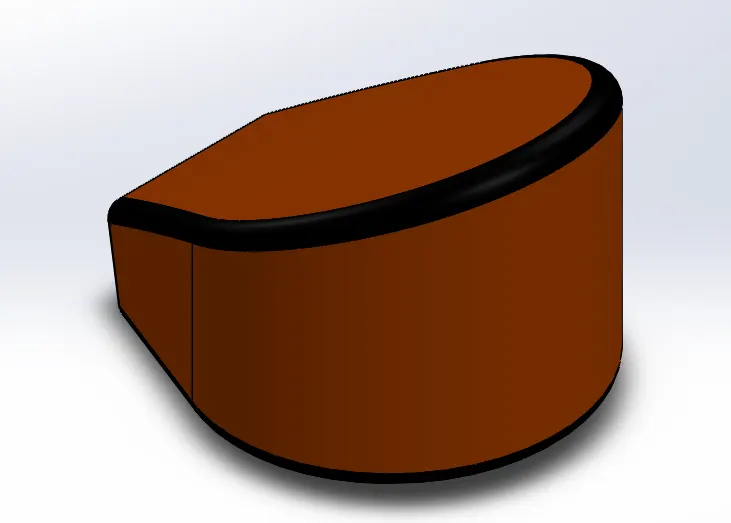
Command used in oil tank:
- Sketch
- boss extrude
- fillet
- shell
- combine
Combine:
Combine command used to merge separate bodies in to single one.
Shell:
It is used to make solid bodies into hollow bodies and also open a face that you selected.
Assembly and render:
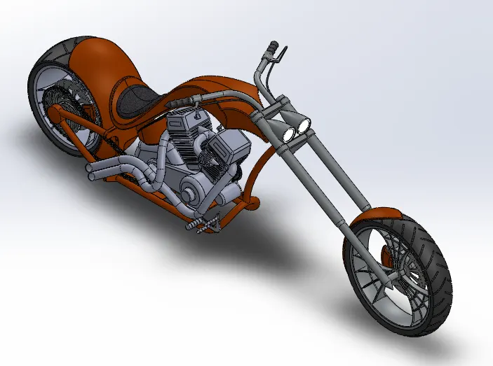
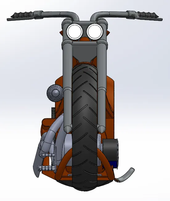
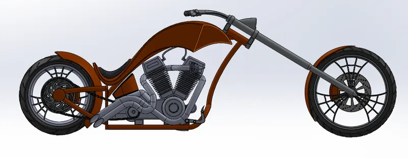
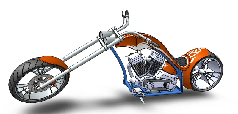
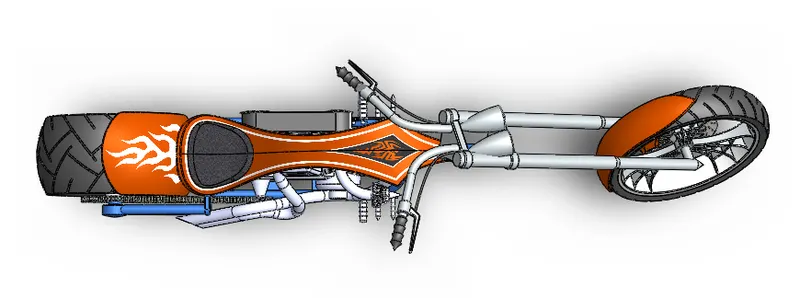
- All the parts of the American chopper is inserted in assembly environment.
- Since all the parts are designed with the reference plane the assemble is done by coincident the reference planes.
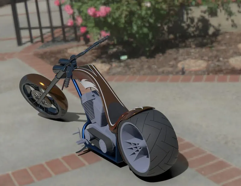
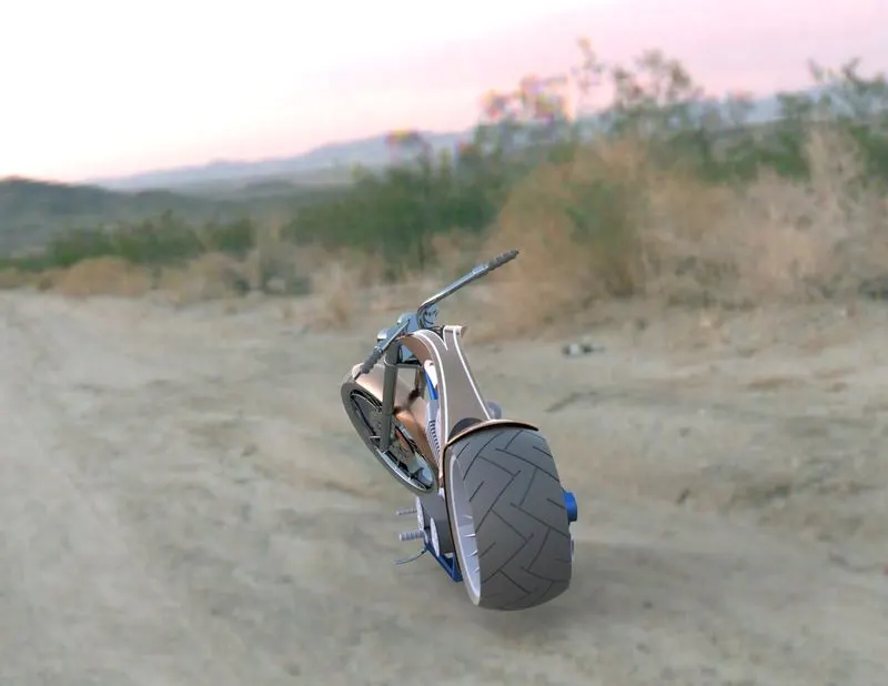
- And the assembled parts imported in solid works visualizer and rendering has done.
Conclusion:
Modelled various parts of the American chopper and assemble it in solidworks and also made a model in realistic way by render.
Outcomes of course:
Learned how to use design a model and rendering using solid works and solidwork visualize software.