Radar Mast & Final Assembly of Yacht
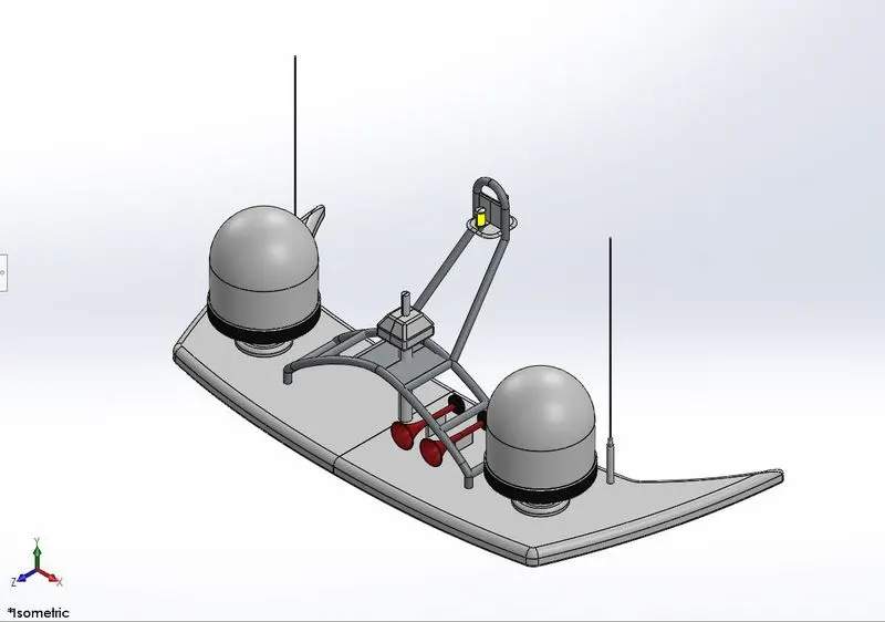
RADARMAST
ISOMETRIC VIEW
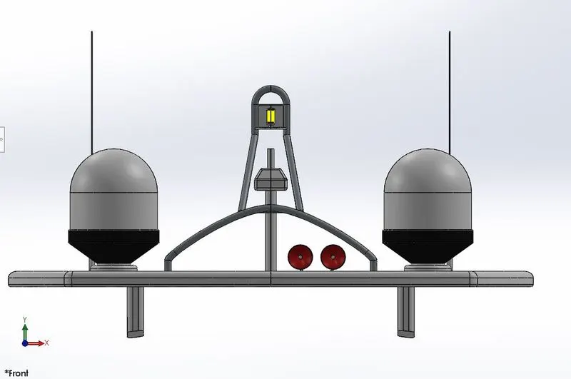
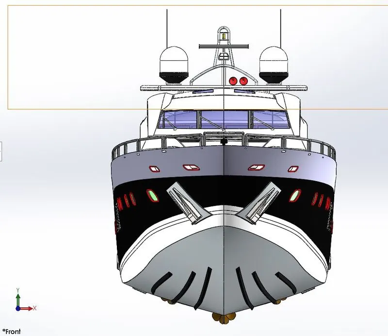
FRONT VIEW
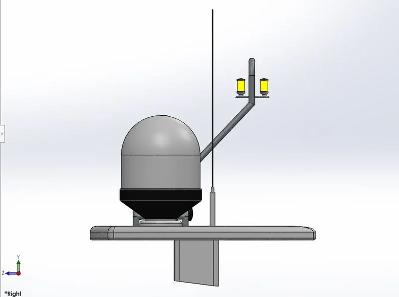
SIDE VIEW
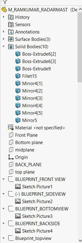
FEATURE TREE
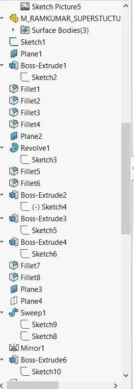
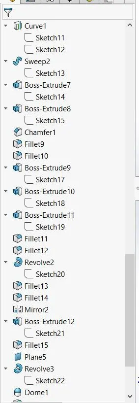
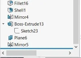
MODELING OF SUNSEEKER PREDATOR YATCH
INTRODUCTION
Solidworks is one of the leading design software in the industry. Majority of OEM's use this software for modeling their products. This was developed by Dassault Systèmes. This is used to create 2D and 3D objects and perform design oriented tasks like assembly and rendering. Solidworks has also a module name Photoview 360 which is soley used for rendering the objects that has been created in solidworks. However this can also done through other third part softwares. This project is focussed on solid modeling of American chopper bike, each and individual bodies seperately. Then assembling it in the solidworks assembly environment. And rendering its photo-realistic image in Photoview360 and SOLIDWORKS VISUALIZE(STAND ALONE RENDERING SYSTEM FOR 3D PARTS AND ASSEMBLIES).
OBJECTIVES:-
- To model individual parts of the Sunseeker predator yatch
- Getting insights of solid modeling , surface modeling understanding the use of various tools in the modeling environment.
- Setting up blueprints. And modeling according to the blue prints.
- Final rendering of the predator yatchin photoview 360 and in Solidworks visu
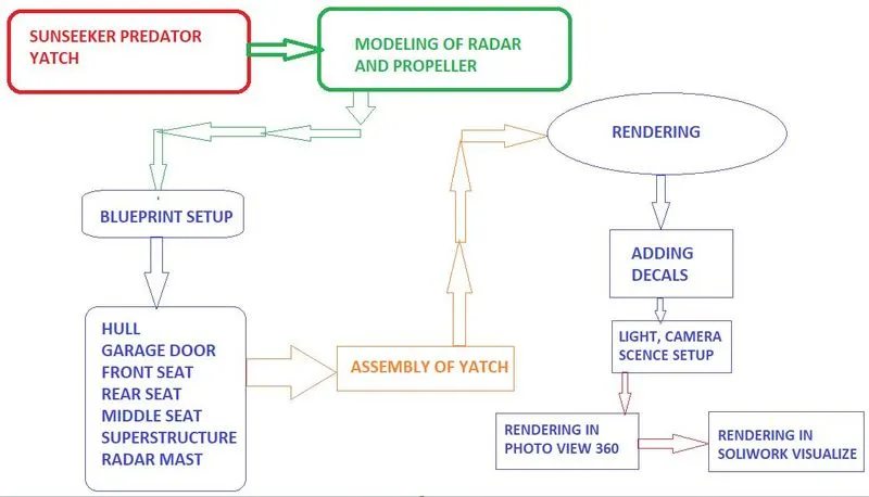
FLOW CHART:-
Basic features used and its nature
Sketch:
The sketch is a 2D representation of the model. These are known as entities in Solidworks. e.g.: line, rectangle, spline, circle, arc etc.
Loft:
The Loft feature allows you to generate complex geometry. It does this by interpolating surfaces between various cross section of the model. These cross sections can be sketches, faces or edges. In the Loft interface the cross sections are considered as Loft profiles.
Dome:
This feature is majorly applied to faces. Select one or more planar or non-planar faces. You can apply dome to faces whose centroid lies outside the face. This allows you to apply domes to irregularly shaped contours.
Extrude Boss/Base:
This feature is used to convert a 2D sketch into 3D model
Extrude Cut:
This feature is used to remove materials from the 3D model. It is just opposite to extrude boss because it cuts a sketch profile while extruding. You can cut in both directions and mainly used for creating holes, channels, slots etc.
Loft surfaces:
Loft surfaces are surfaces generated by multiple 3D curves or existing edges creating a smooth tangency between the selected curves.
Sweep surfaces:
Sweep surfaces are surfaces that are generated from a section curve positioned along a path.
Fill surface:
The fill surface feature constructs a surface path with any number of sides with in a boundary defined by existing model edges, sketches or curves including composite curves.
Surface Trim:
Primarily used to cut away material from a surface and provides two modes: standard and mutual
Surface Knit:
Surface knit is used to knit two free edges / open edges of the surface together into a single surface.
Surface extrude.
This tool is used to extrude a sketch as it is. Unlike Boss extrude this doesn’t create a solid geometry. It will only generate a surface along the extruded direction with respect to the sketch that is been extruded.
Surface offset:
This tool is used to create a offset surface along the given dimension with respect to the original surface.
Delete face:
This tool is used to delete a certain face which can also be filled with its delete and fill option or using some other methods.
Rulled surface:
This tool is pretty much similar to the extrude surface but this tool posses an advantage of being able to incline the extruded surface along the given vector of inclination.
Fillet:
This feature creates a rounded internal or external face on the part. You can Fillet all the edges of a face, edges , loops etc.
Split:
This tool is used to project an entity onto other surface or curved or planar faces. You can also split faces on multiple bodies with one command.
Offset:
Offset one or more sketch entities, selected model edges or model faces by specified distance. For e.g. You can offset sketch entities such as splines or arcs, set of model edges, loops and so on. You can offset finite lines, arcs and splines.
Revolve:
Create a sketch that contains one or more profiles and a Centre line or an edge to use as the axis around which the feature revolves.
Dynamic Mirror:
Dynamic mirror, it is used as you sketch the entities, they are mirrored about the pre sketch entity.
Trim entities:
This tool is used to delete or cut unwanted sketch geometry and or can be used to extend geometry to the next intersection.
Patterns:
The pattern tool allows you to create Patterns along a Planar or 3D curve. You can base your pattern on a open curve or on a closed curve such as circle. In the chain part curve driven pattern is used.
Shell:
Used to convert a solid object into a hollow object by deleting the materials inside leaving only the outer surface and the thickness defined by the user.
Combine:
Combine feature is used to manually combine two bodies into a single solid body or surface.
Chamfer:
A cut on the edge or corner of something that makes it slope slightly rather being perfectly sharp edge.
Linear pattern:
Multiplies a feature or a sketch along the specified path in a linear path as per the number of instances specified.
Circular Pattern:
Multiplies a feature or sketch along the specified circle or a axis of rotation as per given number of instances.
Move/Copy Body:
This feature is used to move/copy the body from one place to another place
Mirror:
Mirror is used to mirror a solid object or a sketch by specifing a mirror line or any planes in the modeling or assembly window.
Projected curve:
Peojected curve is a kind of 3D curve which is projected based on the two different 2D sketches.
Sweep:
With the sweep feature we can create a shape by moving a 2D sketch profile along a 2D or 3D sketch path.
Composite curve:
This feature is used to join two curves and make them a single curve. Eg combining a projected curve to another curve etc.
Mates:
Mates create geometric relationship between the assembly components. As we add mates, we define the allowable directions of linear or rotational motion of the components. We can move a component within its degree of freedom, visualising the assembly behaviour.
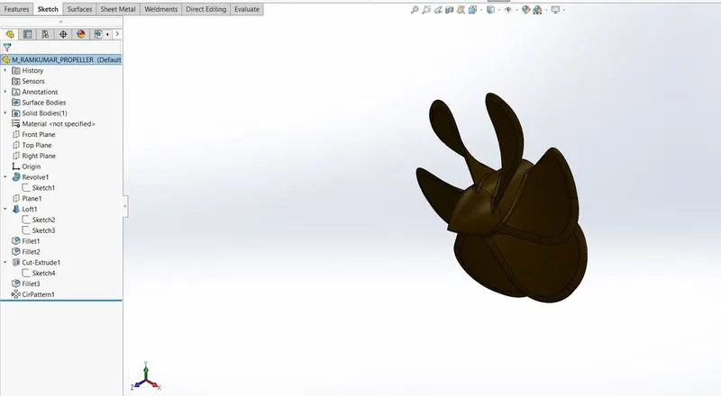
PROPELLER
This is the component which makes the yatch move in the water.
List of features used:
- Sketch
- Revolve
- Loft
- Fillet
- Cut extrude
- Circular pattern
RADAR
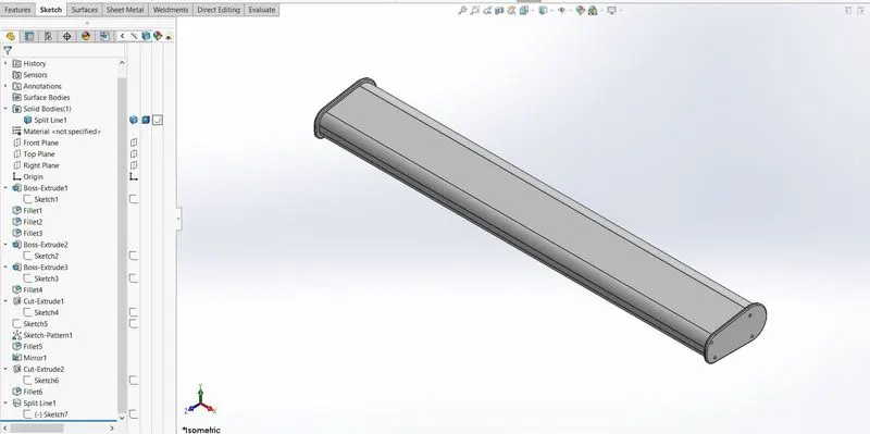
This is the communication device of the yatch when it is sailing in the open sea.
List of features used
- Sketch
- Boss extrude
- Fillet
- Extrude cut
- Sketch pattern
- Mirroe
- Split
BLUEPRINT SETUP
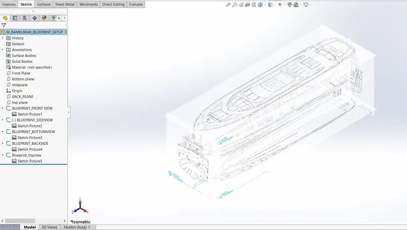
This is the basic mapping of every components about how the should look and where they should be.
List of features used
- Sketch
- Sketch picture
HULL
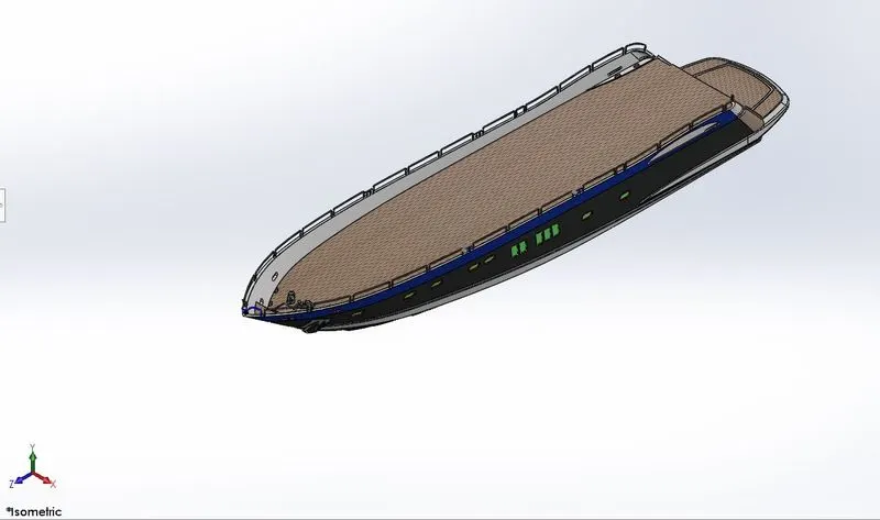
This is the base of the yatch where all other components are being mounted upon.
list of features used
- Sketch
- Surface extrude
- Surface loft
- Delete face
- Fillet
- Chamfer
- Projected curve
- Extrude
- Extrude cut
- Sweep
- Swept surface
- Linear pattern
- Helix
- Revolve
- 3D sketch
- Mirror
- Surface offset
- Surface knit
GARAGE DOOR
A door mechanism to close of the storage space of the yatch.
List of features used
- Sketch
- Extrude cut
- Shell
- Fillet
- Mirror
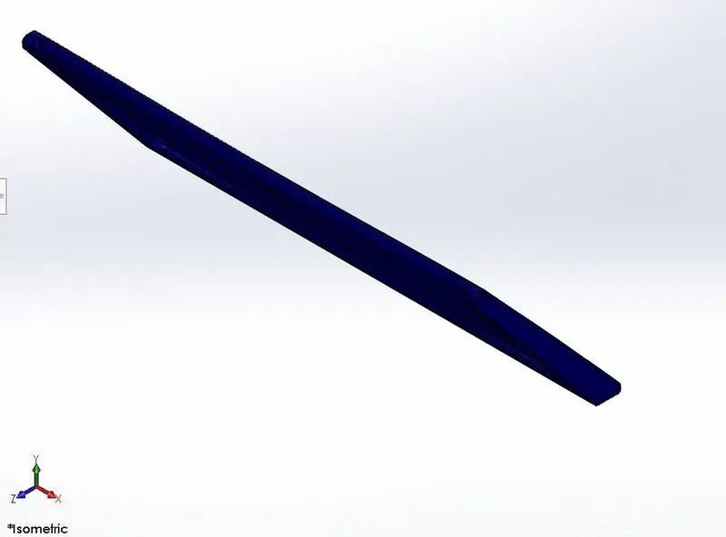
Front seat
Seat structure infront of the super structure.
list of features used
- sketch
- Surface extrude
- Surface sweep
- Surface trim
- Surface loft
- Revolve
- Chamfer
- Mirror
- Dome
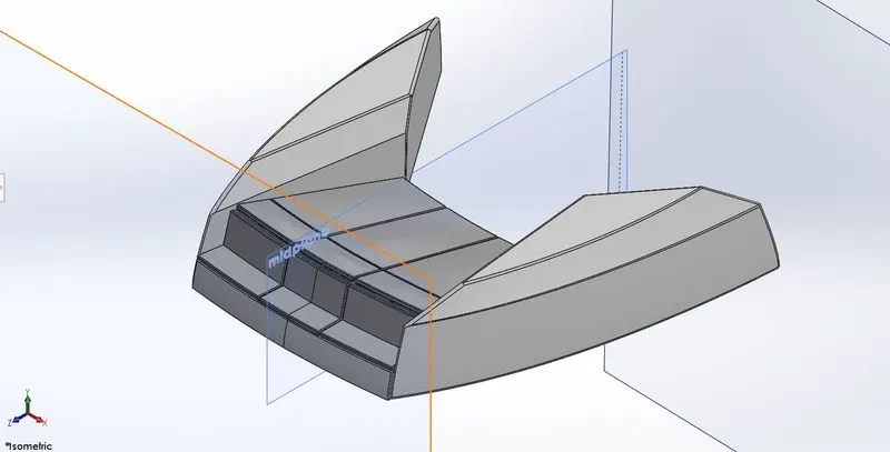
MIDDLE SEAT
Seat structure behind the super structure.
list of features used
- sketch
- Surface extrude
- Chamfer
- Fillet
- Extrude cut
- Mirror
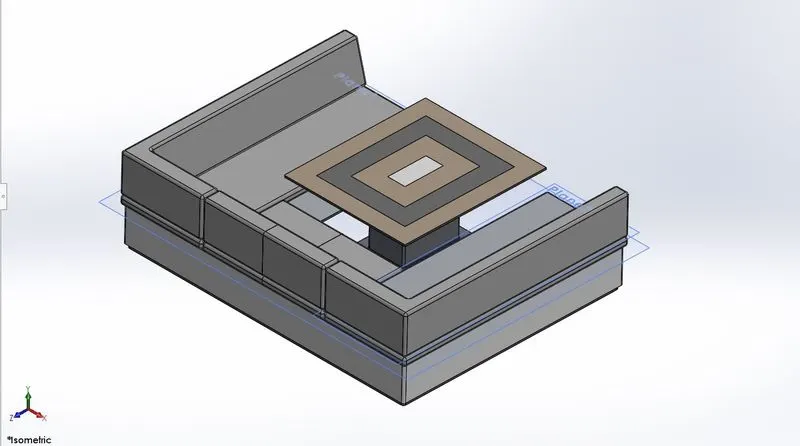
REAR SEAT
Seat structure for passengers in the far end of the deck surface
List of feature used
- sketch
- Surface sweep
- Surface offset
- Rulled surface
- Surface trim
- Surface knit
- Surface extrude
- Surface loft
- Boss extrude
- Extrude cut
- Chamfer
- Fillet
- Mirror
- Revolve
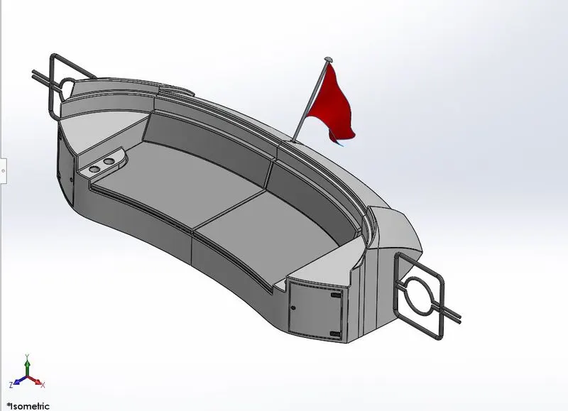
SUPER STRUCTURE
This is the area where all the controls of the yatch and communication equipments will be. It is located upon the deck surface.
List of feature used
- Sketch
- Surface extrude
- Surface loft
- Delete face
- Fillet
- Chamfer
- Projected curve
- Extrude
- Extrude cut
- Sweep
- Swept surface
- Linear pattern
- Helix
- Revolve
- 3D sketch
- Mirror
- Surface offset
- Rulled surface
- Surface trim
- Surface fill
- Suface knit
- 3D sketch
- Thicken
- Dome
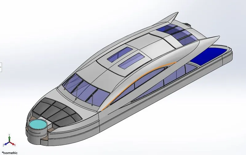
RADAR MAST
This is the main hub which houses radar antenna, radar sensors communication receivers and blow horn and sirens.
List of features used
- Sketch
- Extrude
- Revolve
- Sweep
- Fillet
- Chamfer
- Projected Curve
- Mirror
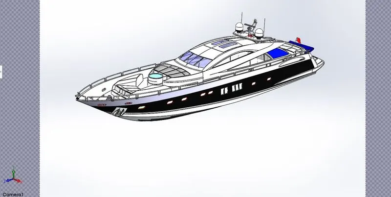
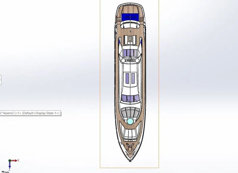
ASSEMBLY OF THE SUNSEEKER PREDATOR YATCH
- Importing the individual components into the assembly file.
2)Fixing the geometrical locationof the hull where all the components will be assembled.
3)Giving all components mates with other components to define its location. And adding a luxury can into the garage of the yatch.
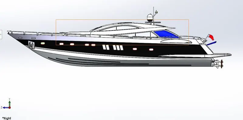
.
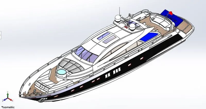
Rendering
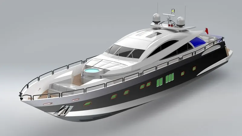
Once the assembly is fully defined, Now the work is to bring it to life using a proper rendering environment.
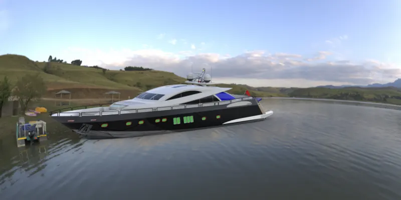
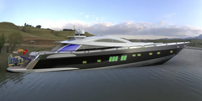
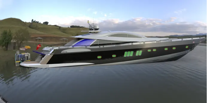
This can be done in two methods, PHOTOVIEW360 and SOLIDWORKS VISUALIZE
- Photovie 360 is a in-built module in Solidworks which is capable of rendering a component or assembly inside the solidworks.
- Visualize is a standalone rendering software. Which can provide good results in terms of appearance and ease of use.
Rendered in Photoview360
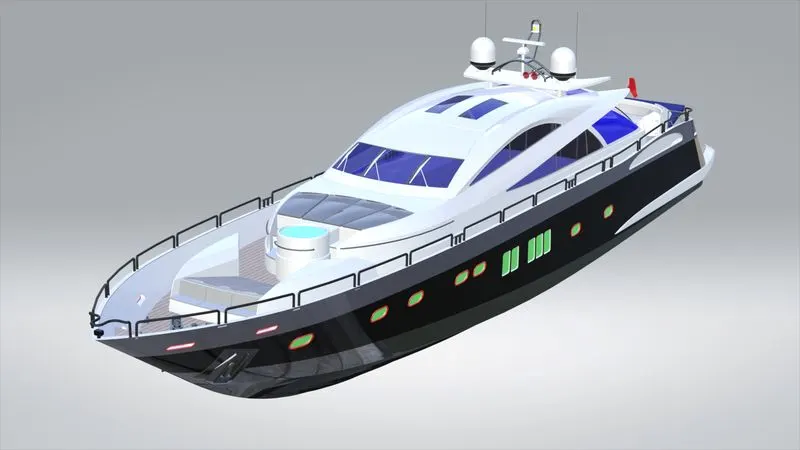
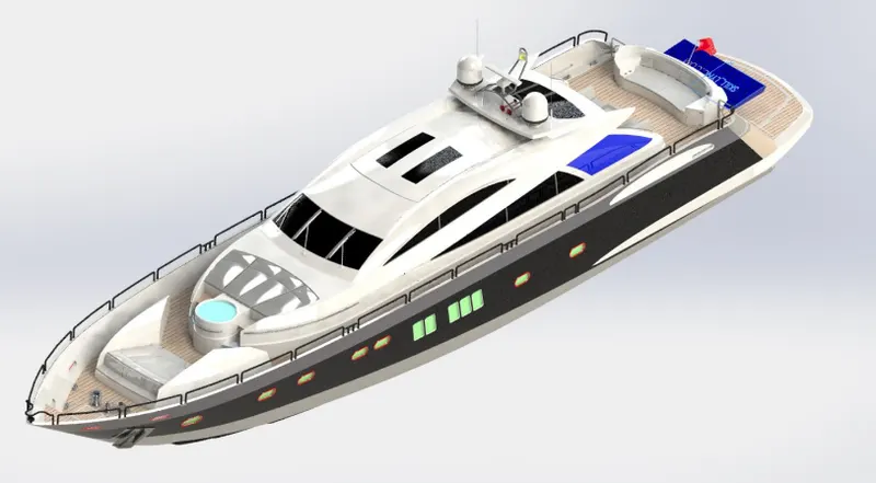
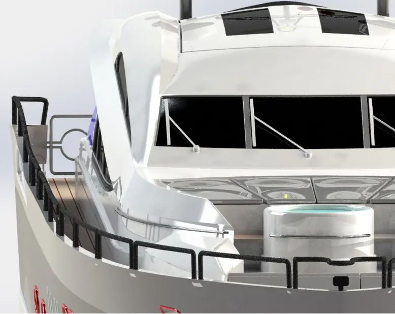
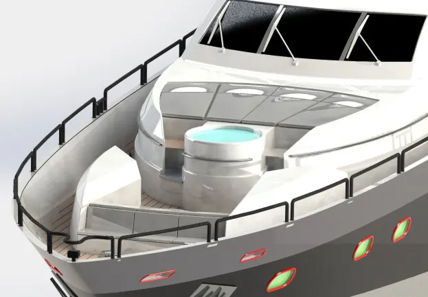
Below images are rendered in SOLIDWORKS VISUALIZE
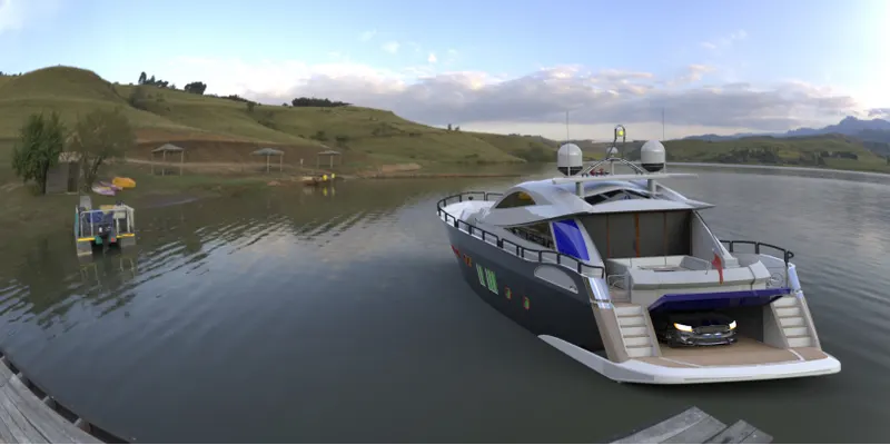
CONCLUSION
All components are modelled as per the given guidelines. And assembled in assembly environment accordingly. Then using photoview 360 the yatch was rendered. After that the model was rendered in the same and imported into the visualize software and done few more renders.
THANK YOU