Radar Mast & Final Assembly of Yacht
PREDATOR YATCH
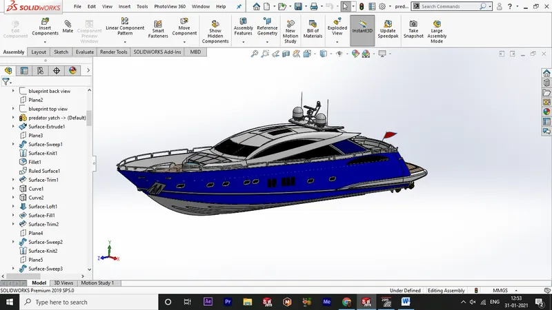
OBJECTIVE :
the objectoive of the modelling of predator yatch is to apply the various types of features and skills learned from the past lessons . to build a perfect predator yatch using all forms of features.
INTRODUCTION
- this report consists of the detailed design methodology of the perdator yatch
- the types of features, tools , used are explained
- a design tool as solidworks had performed good in this design it is easy to understand and use
DESIGN METHODOLOGY
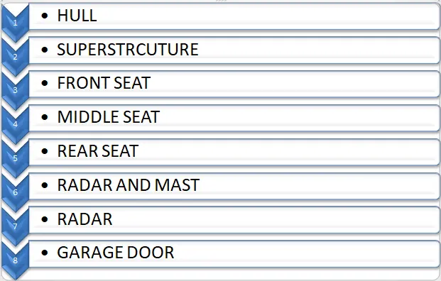
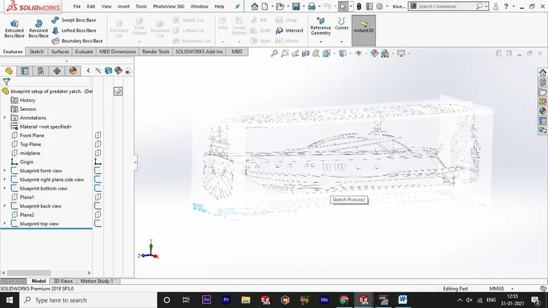
blueprint setup
- open the solidworks software form the taskbar or start menu .
- open a new part file
- then select insert>sketchpicture
- select the yatch blueprint side plane in the midplane and close the sketch.
- next open the right plane and insert the back side bluepritn of the yatch and close the sketch
- next open the top plane and insertthe bottom side of the yatch blueprint and close the sketch
- next use the reference geometry and insert a new plane first reference as back right plane and enter the offset distance as 0 and click ok , and open the plane 1 sketch and insert the front side of the yatch blueprint and close the sketch
- next do the same for the top plane and insert the top view of the yatch blueprint and close the sketch.
- now save the file as predator yatch blueprint
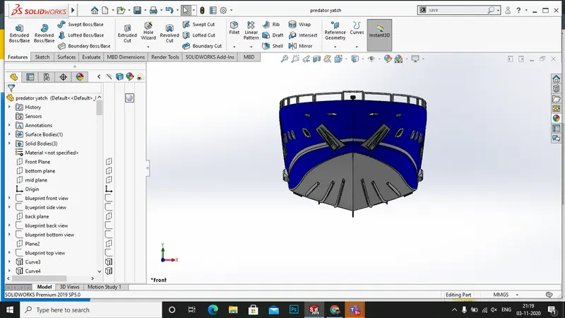
HULL
- open the soldiworks and open the blueprint setup file
- then save as the file as hull.
- now hide the front , back . top and bottom planes .
- now draw the lower part of the hull as in the pdf with required dimensions
- the first feature youll be using is the surface loft use the appropriate values to apply the feature
- the surface loft is a best feature to initiate nice curvy srufaces for automobile sheet metals
- next the upper part of the hull is made a appropriate sketches are drawn
- next use the ruled surface to get the surface as linear one as the lower surface
- use surface > rulesd surface .
- next we have to build the flat surface floor on the hull
- use the planes to create a straight line and exit the sketcdh
- next step use fill surface, the fill surface is the feature which is nice for the more edges and good transition .
- next use the midplane and draw the sketches for the windows in the hull and exit
- use the extruded cut and give the appropriate feactures for light intended cut
- next use the planes in the windows and draw the sketches for swept surface of the windows
- next slect the hull upper wall face and draw the sketches for railing and use the dimension to fully define the sketch
- next use the lofted sweep feature to give a nice railing design and click ok.
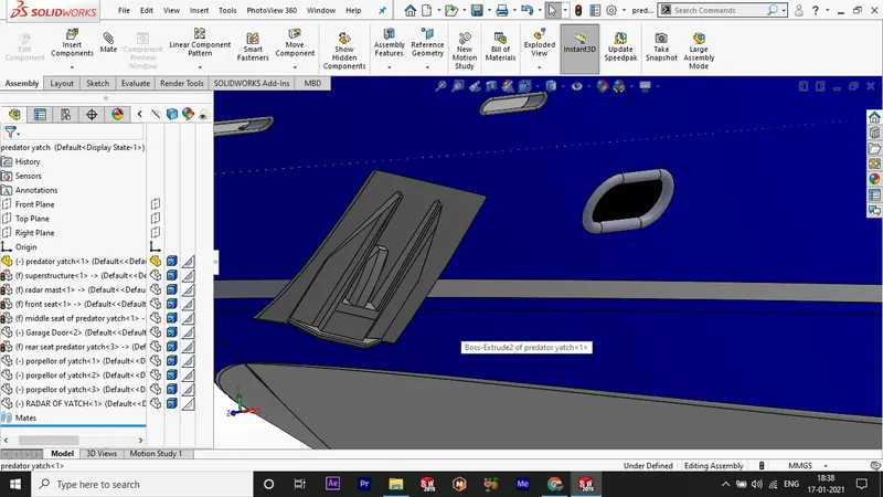
- next use the midplane to draw the sketch for the anchor area and anchor port
- use the extruded boss features for first embeded form and nect use the chamfer features to get a nice anchor .
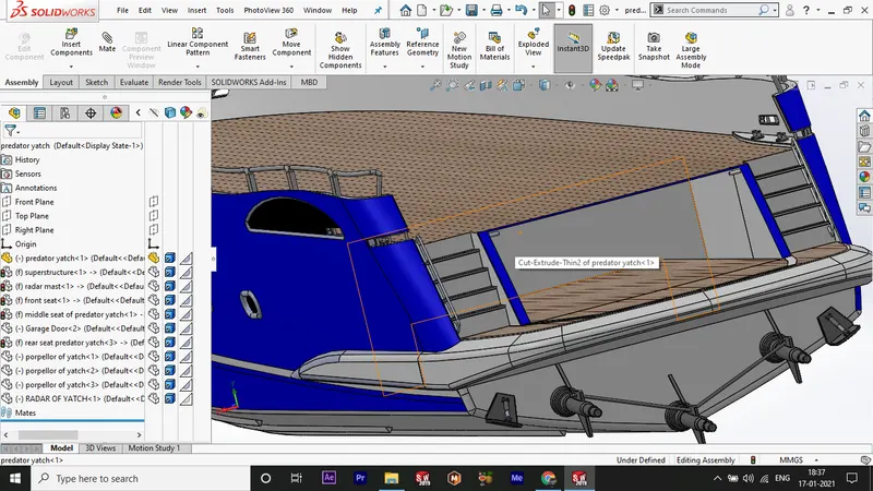
- next selct the back plane and draw the sketches for garage area
- use the extruded cut to cut the garage area in the hull solid region and click ok
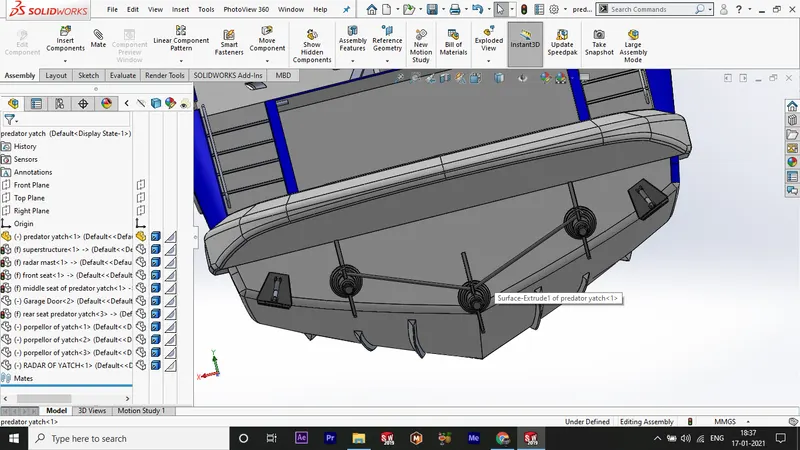
- next again select the back plane and draw the sketches for the propeller shaft and use the extruded boss for nice transition .
- next again do the same for another in the middle .
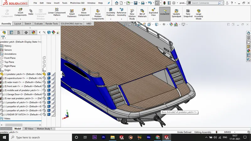
- next select the the face required to draw the sketches for the stairs and draw the appropriate sketches for stairs .
- next use surface extrude and select upto next as end constraints click ok.
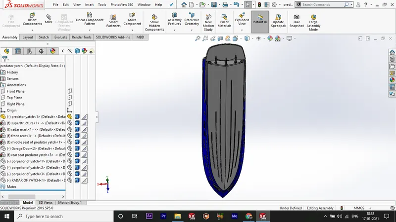
- next select the bottom plane and draw the sketches for water wading wings and use the extruded boss to emerrge it and use chamfer to sharp the edges .
- finally apply the appearances to the hull white for the total part, blue for the hull middle area , grey for the railings , dark grey for the propeller shafts .
- next use the photoview 360 to apply the floor appearances and click ok
- finally use the mirror option select the midplane as plane about and select the part as mirroring part click ok a complete hull is made .
- then save the file as hull .
superstructure:
- open the solidworks and open the part file blueprint setup click ok
- next save the file as superctructure and close the bluepritn file .
- next import the deck surface of the hullby using insert>part and click ok
- select only the surface s the import part .
- next hide the front , back , side view.
- create a new sketch on the deck surface .
- darw the required sketches for the superstructure base extrusion .
- use features>surface> extrude sruface.
- then apply the value and reverse click ok.
- then create the plane on the edge of the extruded surface at back and click ok.
- now draw the sketch for flat surface of the extruded surafce .
- next use the syrface sweep insert > surface > sweep.
- next knit the all surfaces together and click ok.
- next apply the fillets for the extruded surfaces .
- now selevct the inner edge of the extruded surface and use insert > surface > ruled surface .
- now select the midplane and draw the sketches for the trim and click ok
- next select the midplane and draw the sketches for the superctructure rear elevation and clickok
- next again click on top plane and convert the extruded surface edge as converted entities and click ok.
- now use the projected curve and select the first sketch and the second sketches for nice curve , and you will see a nic e curve click ok .
- again slect the midplane and select the outer edge as converted entities and click ok.
- next select the top plane and darw the sketch and splines for the shorted elevation sketches and click ok.
- next use the projected curve and select the bothe sketches you drawn previously and click ok.
- next select the 3d sketch and draw a line connecting the upper line and lower line , click ok .
- next use the lofted surface and selct the two lines and select the 3d sketch line for the curve projection and click ok.
- next open a 3d sketch and draw a line connecting the upper and lower lines at back side and click ok
- next use the surface fill option and slect the boundaries to fill and click ok.
- next again create a plane on the newly created lofted surface edge and click ok
- on the plane create a sketch and convert the edge int o line s and click ok.
- and use extrude ssurface and click ok.
- next use ethe knit surfaces and knit the srufaces craeted tilll now .
- now create a plane at the lower wall sruface .
- create a sketch on the plane and connect the upper extruded surface and lower surface using the spline and click ok.
- next sketch again on the plane and convert the lower wall line into sketch and click ok
- next use the surface sweep and slect the lower line and the spline .clik ok.
- next use the trim tool to trim the extra surfaces .
- now select the midplane and convert the upper elevation edge line into sketch and cilck ok.
- next use extrude surface and use avalue to do.
- next a surface is filled .
- use the trim tool to trim the extra surface .
- now knit the surfaces together again.
- next sketch on the midplane and draw the spline connecting th eupper surface and the lower surface .
- then ius elofted surface and slecte the sketches for loft and click ok.
- next sketch on midplane and draw the spline as shown in the image and click ok.
- again click the top planr and draw the spline as shown and click ok.
- next use the projected curve in reference geometry and select the sketches darwn and click ok.
- now again selectthe middplane an d draw the spline as shown and click ok.
- next slelct the top plane and darw the spliens as shown .
- now use the projected plane and click ok.
- now you will see the curves together forming the curvy surface .
- now use lofted surface and slect the curve 3 and curve 4 and click ok .
- now you can see a good surface curved .(surface loft 4)
- now sketch on the top plane and the offset the edge of the surface loft 4 and click ok.
- now sketch on mid plane draw a verticle lines coonection midplane to loft 4 edge and click ok.
- now darw the spline as loft 4 and click ok
- next use the projected curve and select the sketch 21 and 20 and click ok a curve appears curve 5
- nextopen a 3d sketch and draw a line connecting the curve 5 and the loft 4.
- next use the lofted surface , and select the loft 4 edge and the curve 5 as loft region and the 3d sketch as curve projection and click ok.
- next open the midplane and draw a spline as blueprint for the top rooof and click ok .
- then use the 3d sketch to connect the sketch and the loft5 and click ok.
- then use the surface loft in the insert menu and selcet the sketches drawn and select the curve guide as 3d sketches and click ok.
- a nice lofted roof surface is formed .
- now open a 3d sketch and connect the loft 6 and the loft 4 with a spline .
- then use the surface loft and click the sketch 22 and sketch 23 as curve and 3d sketch as guide curve .
- create a 3d sketch and select the edge of the surface fill 1 inner edge and convert the edge int o sketch .
- next use the ruled surface and select the edge as option and click ok.
- next use the trim tool to trim the extra surfaces .
- next extend the surface of the loft 6 and extend the surfac eof the loft 5 click ok.
- now use ethe top plane and draw the splines for the surface cu tof the extended surface of loft 6 and loft 5.
- next use the surface trim tool to trim the last surface .
- next use the surface lfot to form surfac ebetween the surface extrude 2 to the loft 6.
- next use ethe knit surfaceas and select all the features done till now and use the gap control to control the gaps between surfaces .
- next select the deck surface and open sketch on it ,
- draw the sketch for the closing of rear surfaces and click ok
- next use the surface>extrude and select thesketch and click ok.
- again create sketch on the hull surface and draw the sketch for the closing of rear side.
- use the surface extrude and click ok.
- next in the inside of the superstructure click on the surface and use the trim tool and trim the part upto available.
- then once again knit the parts together .
- next see for all edges for blue lines if it appears clear it by using gap control or extend surface option then a solid body is created in the feature tree.
- open sketch on the mid plane and conver the edge in to line in the front side .
- next use the extend surface and click ok.
- now use the trim tool to trim the required design .
- now sketch on the deck surface and draw the sketc for the extrude surface and click ok.
- now trim the extras
- now open the mid plane and draw the required sketch and use the loft surface to form the surface .
- now craete a sketch on the deck surface and darw a circle on the sketch and click ok.
- offset the cirlcle and clos ethe sketch .
- now use the extrudedd bosee /bass and form upto a value .
- the again convert the edge of the inner circle and form a extruded boss/baseand clcick ok.
- now use plane to draw the sketches for the stairs and form the stairs as shown in the picture using the extended bosss/base
- now form the sketch on the stairs and draw the sketch for the beeding of the stairs .
- now sketch on the mid plane and darw a straight line all over the lenghth and use the surface extrude and select the dircation as through all.
- now use the trim tool to trimm the extra surfaces.
- now use the mirror option to mirror the parts about midplane and clikc ok .
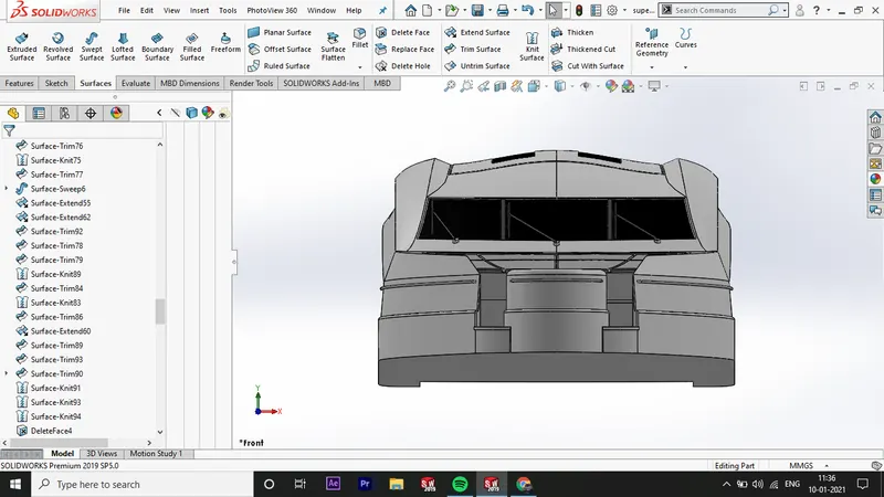
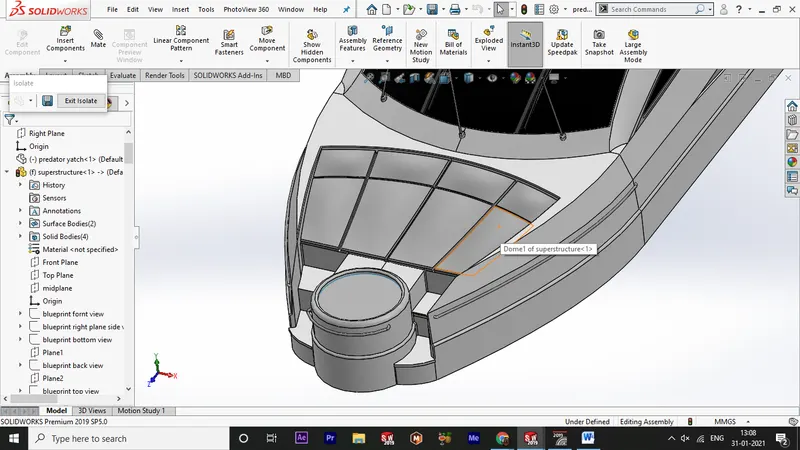
- now on the front bonnet area click the bliue surface as shown and dra wthe sketches
- now use the extruded cut to make an light cut in the surface to get a nice look.
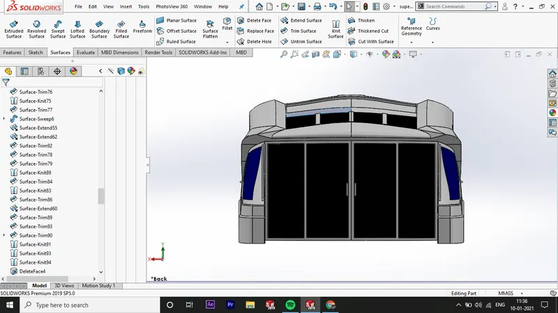
- now open a sketch on the back plane and draw the sketches for the door extruded cut and use the toolto make the grooves on the door.
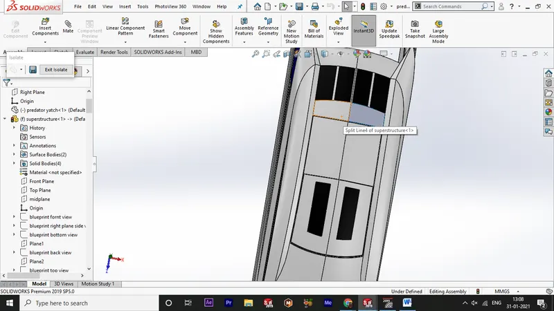
- now on the top plane draw the sketches for the roof glass grooves and use the extruded cut and make the groove
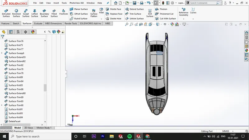
- now apply the appearances and decals on the supersrtuctures .
- now save the file .
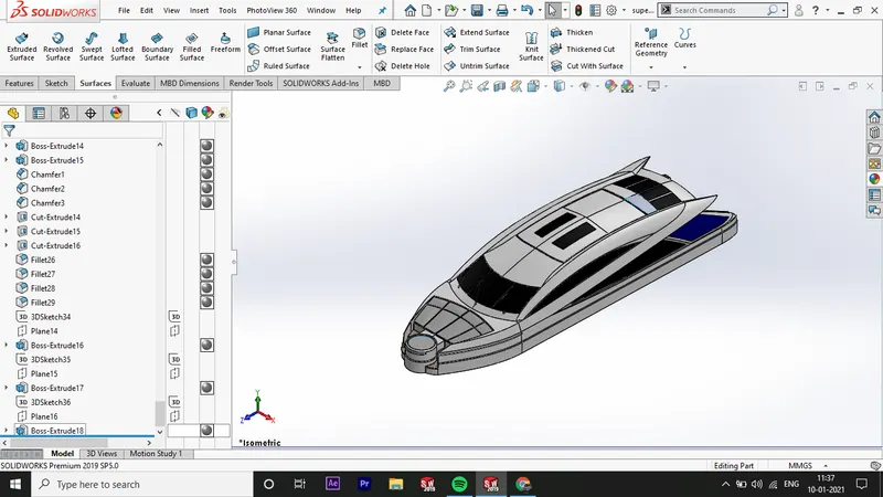
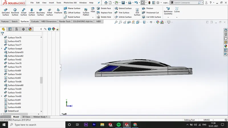
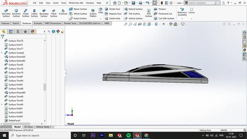
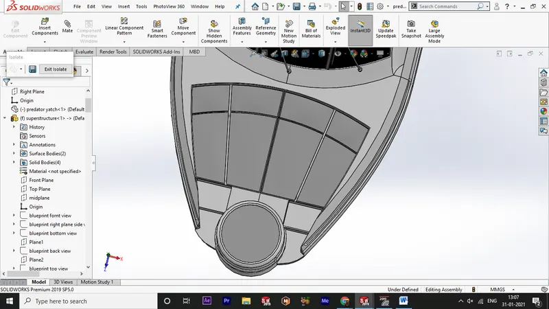
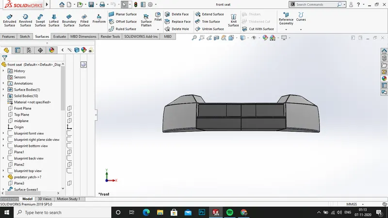
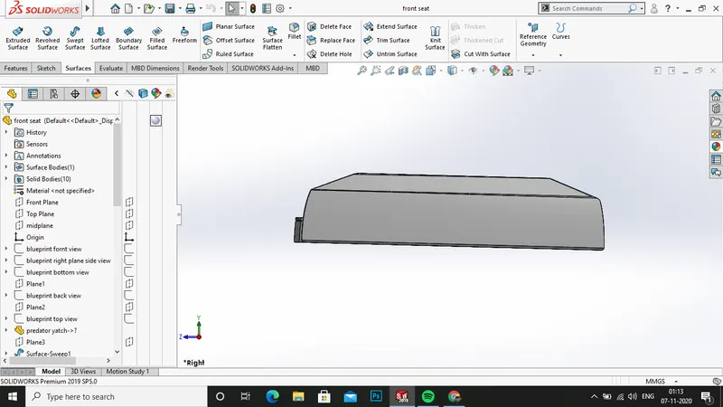
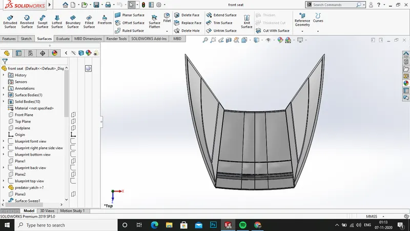
front seat:
- open the solidwors and open the blueprint setup file .
- now save the file as front seata nd click ok.
- now import the part insert>part and click ok.
- now select only the surface bodies and clickok.
- now hide the forn , bcak , and bottom view .
- on the top plane open a sketch and draw the spline as shown and lcik ok.
- now create a plane on the end of the spline and clcik ok.
- now create the sketch on the plane 1 and darw the spline as shown and click exit .
- now use the surface sweep and select the sketch 1 and sketch 2 click ok.
- now craete a sketch on the deck surface and darw the lines as shown and close the sketch .
- now use the surface extrude
- now trim the extra srufaces using the trim tool.
- now use the fill surfaces and select the edges of the extruded surfaces .
- now on the bottom of the seat use ethe fill surfaces and select the three lines and click ok.
- now use the knit surface option and knit together and use gap control.
- now select the other side surface and sketch on it draw the required sketch for the seat and and draw the axis form the origin to the sketch .
- now use the revolve boss/base and enter a value , clcik ok
- now use the fillet in the edges and click ok.
- next select the blue surface as shown and draw the sketch and form the revolve boss/base and click ok.
- now select the top pkane and sketh on the plane and draw the sketch for thegropves on the seat to be placed and clcik ok.
- now use the extuded cut option to make an groove and click ok .
- now use the mirror option and select the side face as mirror about and select anywhere in the part and click ok.
- now select the top plane and draw the sketches for the grooves on the seat upper area and use the extruded cut select the upto surface option .
- select the pink surface and click ok.
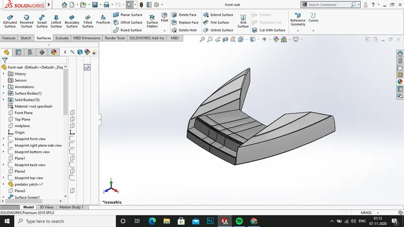
- now apply the fillets wherever the sharp edges are seen apply the appearances as white to all the areas .
- then save the file .
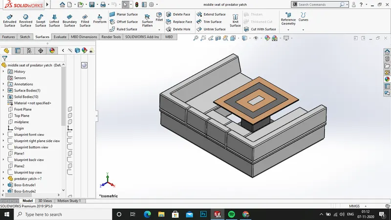
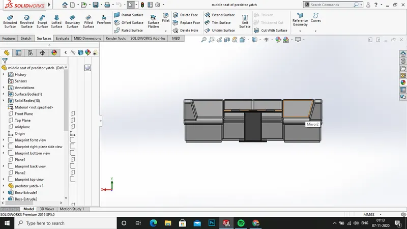
middle seat:
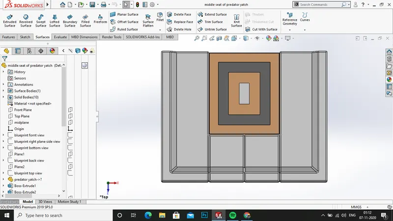
- open the solidworks file and open the blueprint setup file
- now save the file as middle seat and close the blueprint file .
- now import the deck surface as insert>part and click ok.
- now select only the surface bodies .
- now hide the front,back and bottom planes .
- create a sketch on the deck surfaces .
- draw the sketches for the extruded surfaces .
- now use the extended boss/base to form upto a value .
- again click on the extruded surface and create a sketch on it .
- now use ethe ofset entities and select the face of the seatand click ok .
- now use the extruded boss/base and form upto a value.
- again draw the sketch on the face of the seat and extrude boss/bas eit .
- now create a plane on the seat face and click ok.
- now draw the sketche son the plane for seat leaning partb .
- use the extruded boss for making it .
- now use the chamfer option for making the leaning part more angled one .
- now mirror the one side as double one
- use ethe mirror option and select the face as plane and part as body .
- now create a sketch on the deck surface .
- darw the sketch for the table and click ok
- now use the exturded boss for the table bottom support .
- and now darw a sketch on the bottom support face and draw the sketch for the table .
- now use ethe etxrdued boss for the table top.
- now apply the appearances as shown .
- save the file.
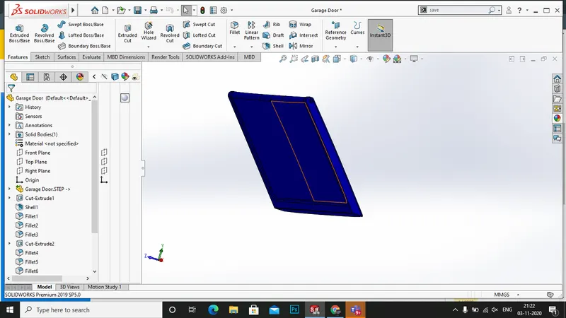
garage door:
- open the solidworks file and open a new part file.
- opne the saved part file garage door.
- create a new sketch on the blue surface as shown .
- make an extruded cut and click ok.
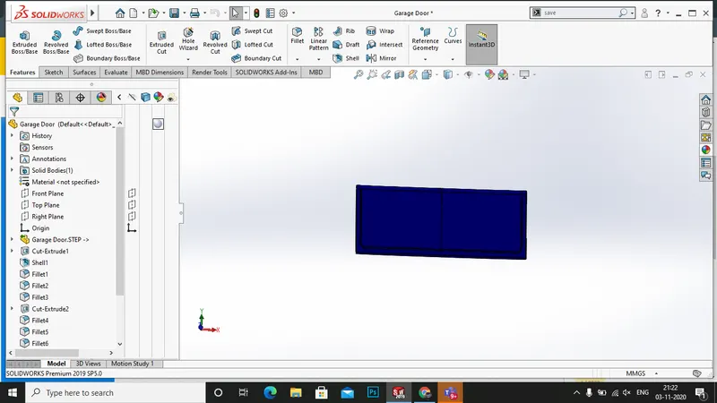
- slect the three blue edges and use the shell option insert>features >shell.
- create the fillet wherever required.
- now create a skertch on the blue surface and draw the circle for the fitiing of hull .
- next make an exturded cut in the sketch and enter upto a value and click ok.
- now apply the fillet in the sharp edges and click ok.
- now craete a large fillet on the upper part of the door.
- next use the mirror option to mirror the one side to other and click ok.
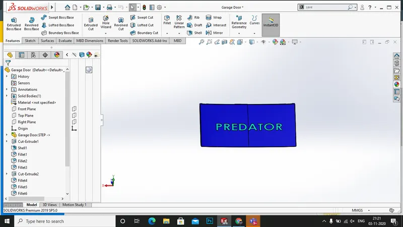
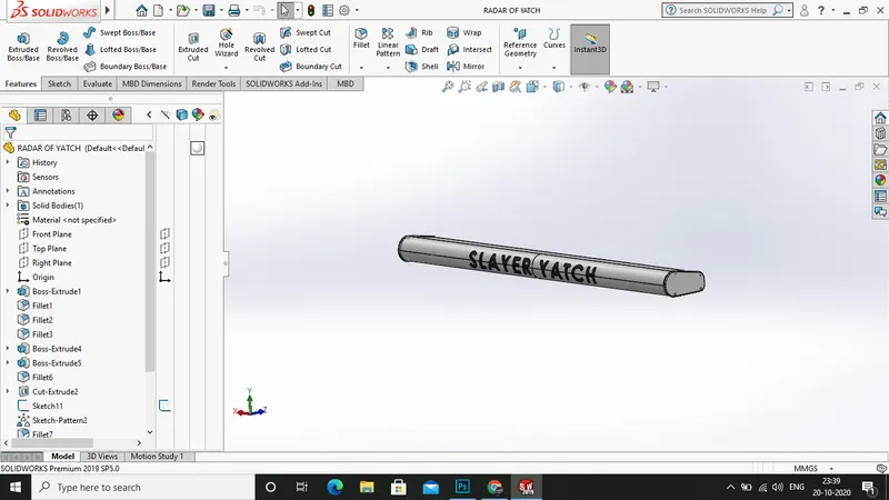
- now craete a new plane on the right plane and draw the text required as yatch and click ok .
- now use the extrudedd cut and make a grooves as by slelcting the direction as upto surface and select reverse offset and clcik ok.
- then apply the appearances as blue to the part .
- then save the file .
radar:
- open the solidworks and open a new part file .
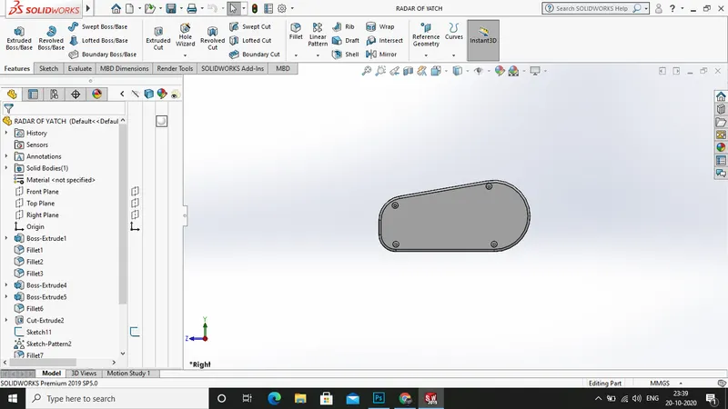
- then create a new sketch on the right plane and draw the sketches as shown .
- then use the extruded boss option to extrude upto a value and clcik ok.
- now use fillet in the upper edge and the lower edge .
- now select the blude face shown and draw the sketches for theembedded bolts .
- now use the appropriate the concentric circles for the bolt formation .
- next slecet the b;ue face and draw the sketches for bolts and extrude boss it .
- then use the fillet option and click ok.
- now again darw a skethc on the bolt face and darw a polygon and make an extrude cut on it .
- then use ethe linear mirror pattern to mirror in the same face .
- then create fillets on the edges.
- now mirror the one side to other by mirror option .
- then select the blueface and darw the sketch for the hole for intersecting radar .
- then use ethe extruded cut an dclick ok.
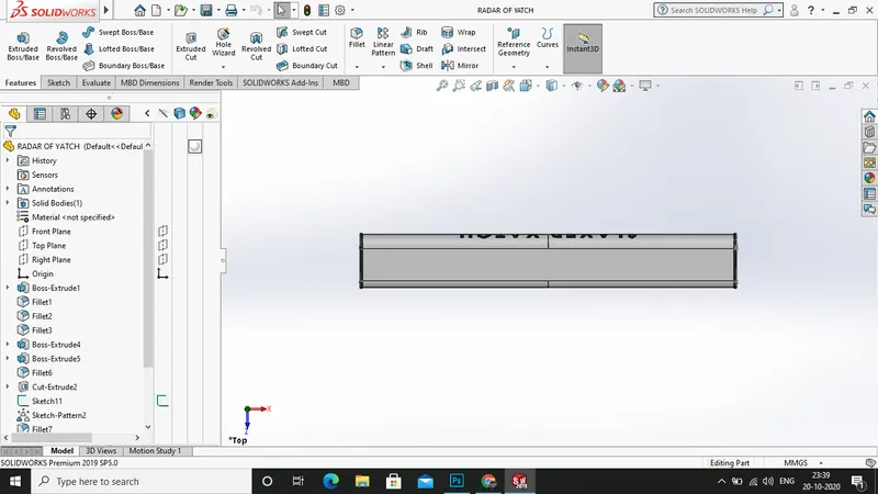
- then select the fornt plane and draw the sketch for the text as radar and click ok then use ethe extruded cut to make a groove.
- then apply the appearances as white and grey to the part .
- then save the file as radar .
- create a 3d sketch and select the edge of the surface fill 1 inner edge and convert the edge int o sketch .
- next use the ruled surface and select the edge as option and click ok.
- next use the trim tool to trim the extra surfaces .
- next extend the surfac eof the loft 6 and extend the surfac eof the loft 5 click ok.
- now use ethe top plane and draw the splines for the surface cu tof the extended surface of loft 6 and loft 5.
- next use the surface trim tool to trim the last surface .
- next use the surface lfot to form surfac ebetween the surface extrude 2 to the loft 6.
- next use ethe knit surfaceas and select all the features done till now and use the gap control to control the gaps between surfaces .
- next select the deck surface and open sketch on it ,
- draw the sketch for the closing of rear surfaces and click ok
- next use the surface>extrude and select thesketch and click ok.
- again create sketch on the hull surface and draw the sketch for the closing of rear side.
- use the surface extrude and click ok.
- next in the inside of the superstructure click on the surface and use the trim tool and trim the part upto available.
- then once again knit the parts together .
- next see for all edges for blue lines if it appears clear it by using gap control or extend surface option then a solid body is created in the feature tree.
- open sketch on the mid plane and conver the edge in to line in the front side .
- next use the extend surface and click ok.
- now use the trim tool to trim the required design .
- now sketch on the deck surface and draw the sketc for the extrude surface and click ok.
- now trim the extras
- now open the mid plane and draw the required sketch and use the loft surface to form the surface .
- now craete a sketch on the deck surface and darw a circle on the sketch and click ok.
- offset the cirlcle and clos ethe sketch .
- now use the extrudedd bosee /bass and form upto a value .
- the again convert the edge of the inner circle and form a extruded boss/baseand clcick ok.
- now use plane to draw the sketches for the stairs and form the stairs as shown in the picture using the extended bosss/base
- now form the sketch on the stairs and draw the sketch for the beeding of the stairs .
- now sketch on the mid plane and darw a straight line all over the lenghth and use the surface extrude and select the dircation as through all.
- now use the trim tool to trimm the extra surfaces.
- now use the mirror option to mirror the parts about midplane and clikc ok .
- now on the front bonnet area click the bliue surface as shown and dra wthe sketches
- now use the extruded cut to make an light cut in the surface to get a nice look.
- now open a sketch on the back plane and draw the sketches for the door extruded cut and use the toolto make the grooves on the door.
- now on the top plane draw the sketches for the roof glass grooves and use the extruded cut and make the groove
- now apply the appearances and decals on the supersrtuctures .
- now save the file .
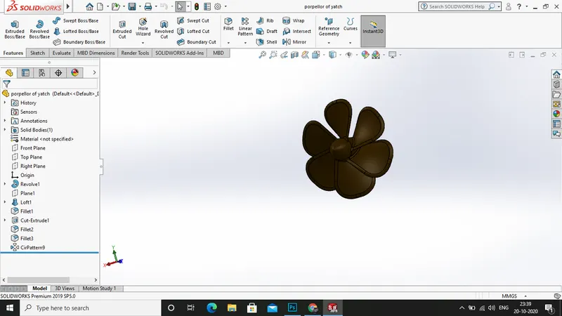
propeller:
- open the solidworks file and open a new file.
- open the part file .
- then start with creating a sketch on the right plane and draw the shown sketch with required dimensions and close the sketch .
- then use the insert>features>revolve boss/base and select the straight line as axis of rotation and click ok.
- then a nice propeller base is available.
- then create a sketch on the top plane and darw the sketches as shown a 3 oitn corner rectangle and close the skketch.
- then create a plane on the top plane and clcik ok.
- then craeate a sketch on the the plane 1 and dimension it .
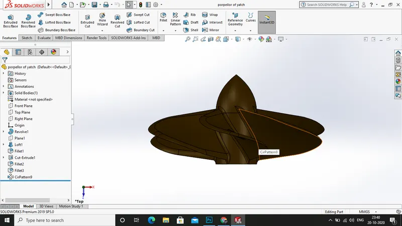
- then use the insert> features > lofted boss/base and select the sketch 2 and sketch 3 .
- then click ok to get the nice transition of the propeller blade make sure the green balls appear on the same side .
- then apply a round fillet on the corner edges of the propeller blade .
- then slect the blue surface shown and draw the sketch of the insertion of the propeller shaft .
- then make the insert>features >extruded cut and make it upto a value.
- then apply the fillets on the round edges of the blade and clik ok .
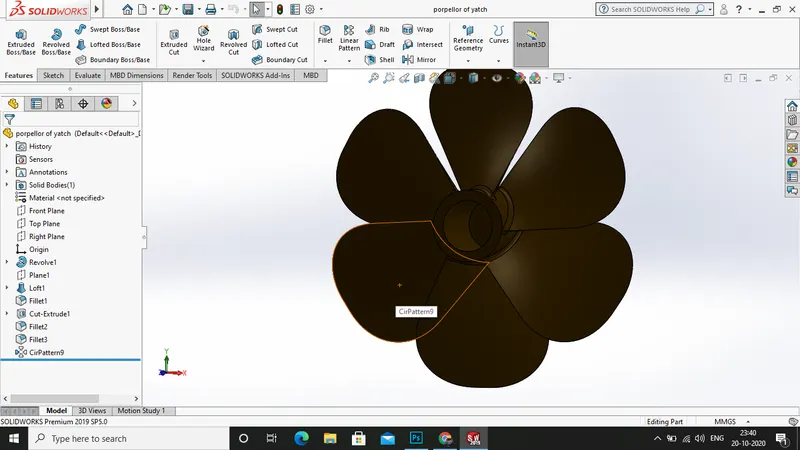
- then use the insert>pattern mirror > cirular pattern.
- then select the instances as 3 and the degrees as 360 and the click ok.
- then apply the apearances as brown colour to the proller blade .
- then save the files as propeller blade .
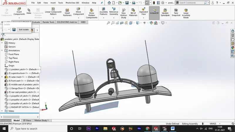
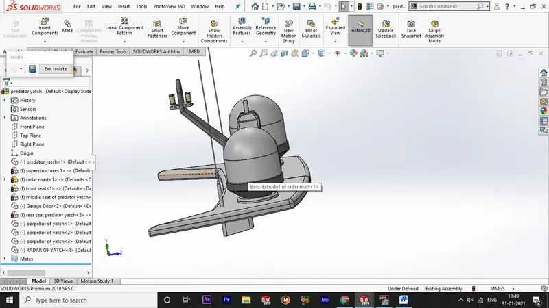
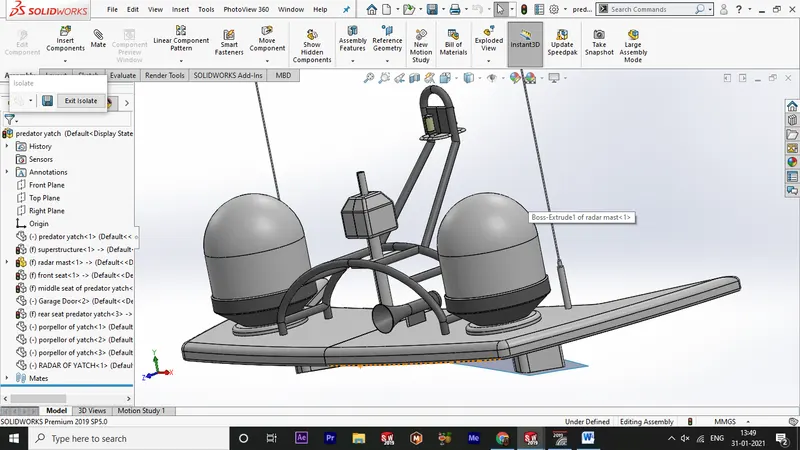
radar and mast :
- open the solidworks file and open a new part file .
- then open the bluepritn setup file ans save as radar and mast .
- then open the insert>part and import the superstructure saved surface body for the radar and mast .
- then hide the front, backand bottom view of the blueprint setup.
- then create a sketch on the mid plane ,
- darw the sketches for the radra base surface and close the sketch .
- then craete a new palne reference as midplane .
- then create a sketch on the plane 1.
- then select the view to top plane and draw the required sketches for the base surface and mark the dimensions for the fully defined sketch .
- then clsoe the sketch and use the insert>boss/base>extrude
- select the sketch 1 as the counter and form the solid upto a value the clcik ok .
- then apply the fillets in the sharp edges of the surface .
- then create a new plane on the radr front plane as reference and click ok
- then create a sketch on the plane 2 and draw the sketch for the radar doom close the sketch .
- then use the insert>boss/base>revolve and select the concentric line as axis of rotation and and apply the revolve and click ok.
- then select the blue surafce shown and craete a sketch on it .
- the use ethe extruded boss/base on it for the antenna .
- then again clcik on the extruded face sketch on it and make an extruded boss and click ok.
- the agaian clcik on it and make a upto alenght and use the extruded boss/base and click ok.
- then apply the fillet on the edge of the antenna and clcik ok.
- then create a new plane and reference as plane 2 and click ok.
- the create asketch on the plane 3 and draw the sketches for value .
- then close the sketch again create a plane on the the sketch skecth 7 and click ok .
- then craete a sketch on the plane 4 and draw the circle for the railing sweep
- then craete the swept boss/base and select the sketch 7 and the sketch 8 as points and clcik ok.
- a railing appears .
- then use the insert>pattern mirror> mirror and select the plane about a splane 2 and the part click ok.
- then craete a sketch on the plane 2 and draw the sketches for the connecting pipe between two railings as shown .
- thenclick ok and use the extruded boss/base and use ethe upto next option as direction value .
- now create a sketch on the mid plane and drawthe sketches for the radar connections as shown .
- then create a sketch on the plane 2 and draw the sketch for the projection of curve .
- then use the reference geometry>projected curve and select the sketch 11 and sketch 12 click ok
- then a nice curve appears .
- create a new sketch on the midplan and draw the sketch for the sweep click ok
- and use the swept boss/base and click the cirlce and the curve 1 click ok.
- then create sketch on the blue surface shown adn draw the sketch for the radar boom .
- then use the insert>boss/bas e>extrude click ok.
- then again create a sketch on the face of the extruded one and create a sketch and use the insert >boss/base >extrude and click ok.
- then apply the fillets and chamfer to the extruded one.
- then create a sketch on the mid plane and draw the sketches with coincident on the railing of radar and close the sketch .
- next use the extruded boss/base and lcik ok.
- then apply the fillets an dchamfer wherever shown .
- then create the sketch on the midplane and draw the ketches for the horn and close the sketch
- then use ethe revolve boss/base and select the axis as construction line and set the degree to 180 .
- clcik ok and apply the fillets in the revolve boss/base .
- then use the insert>patternmirror > mirror use the plane about as the face 1and click ok.
- create asketch on the bottom of the surface and draw the sketcches for bottom support and click ok.
- then use the extruded boss/base and select the upto surface and select the base surface as selection and click ok.
- then apply the fillets in it
- then create a plane in the mid plane as reference and draw he sketches for the funnel horns and close the ketch
- next use the revovlve boss/base and select the axis of rotation as the straight line shown and click ok.
- next apply the dome to the horn and click ok.
- next use the insert>pattern mirror> mirror and select the midplane as plane about select the part to mirror and click ok.
- now apply the appearances and give the appropriate detaisl on it .
- then save the fiel as radar and mast .
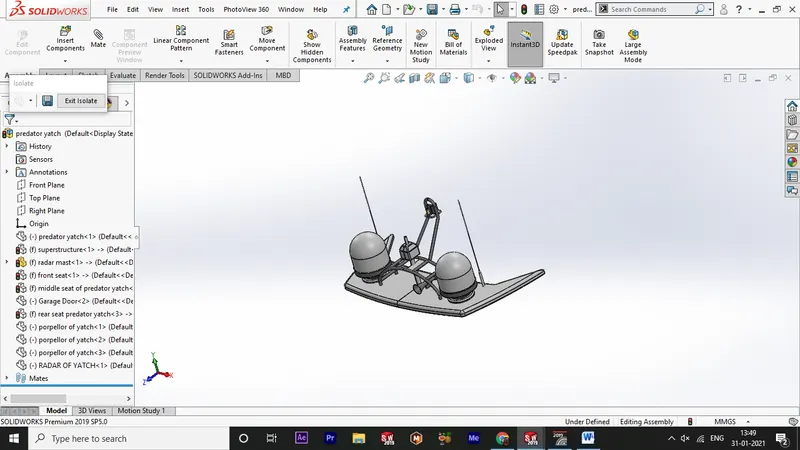
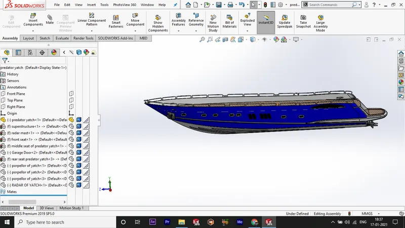
assembly :
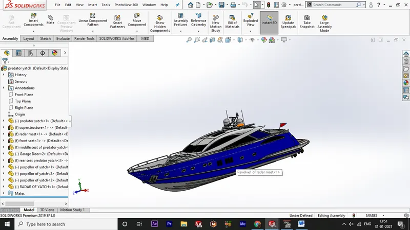
- open the solidworks software and open a new assembly file .
- then in the menu import the hull in the feature tree by insert>components >hull and click ok
- the hull will be fixed automatically .
- next in the command manager use ethe insert components and browse the superstructure and click ok .
- next do insert>components>rear seat and click ok .
- next use the mate comoinenets and select the coincident option and select the bottom of the rear seat and the top of the hull and click ok.
- use the distance option and set the poitns coincident .
- then insert>components > fornt seat and clcik ok
- then use the mate componenets and select the coincident select the bottom of the front seat and the top of the hull click ok.
- next insert the middle seat component.
- use the mate component and select the bottom of the middle seat and the top of the hull and click ok.
- next insert>component > insert the garage door
- now use the mate components and select the concentric option and slect the ggarage door outer roller and the hull garage door fixing area inner hole and click ok .
- netx use ethe mate compinenets and select the coincident and secet the face of the shown a nd the face of the garage door shown face . click ok.
- next us ethe insert>components >propeller baldes click ok
- use the mate compoenets to mate the blades to the shaft .
- next use the insert components> radar and mast click ok.
- next us ethe mate compoenets to coincident the radar and amst to the suoerstrcuture .
- next use the insert>component>radar and lcick ok.
- next us ethe mate componenst to mate the radar to the radar and mast and click ok.
- finally save the fileas assembly of prdator yatch .
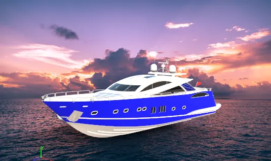
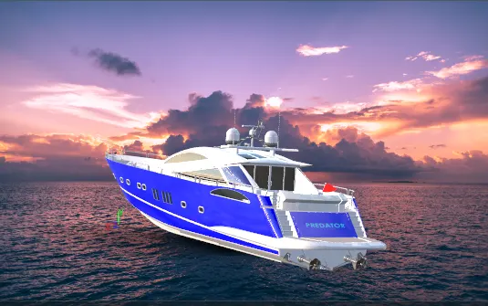
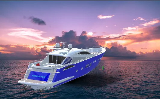
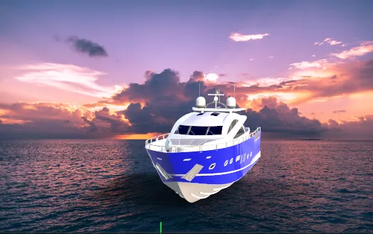
rendered images :
THANK YOU