Photo Realistic Rendering
ASSEMBLY OF CHOPPER MODEL
OBJECTIVE :
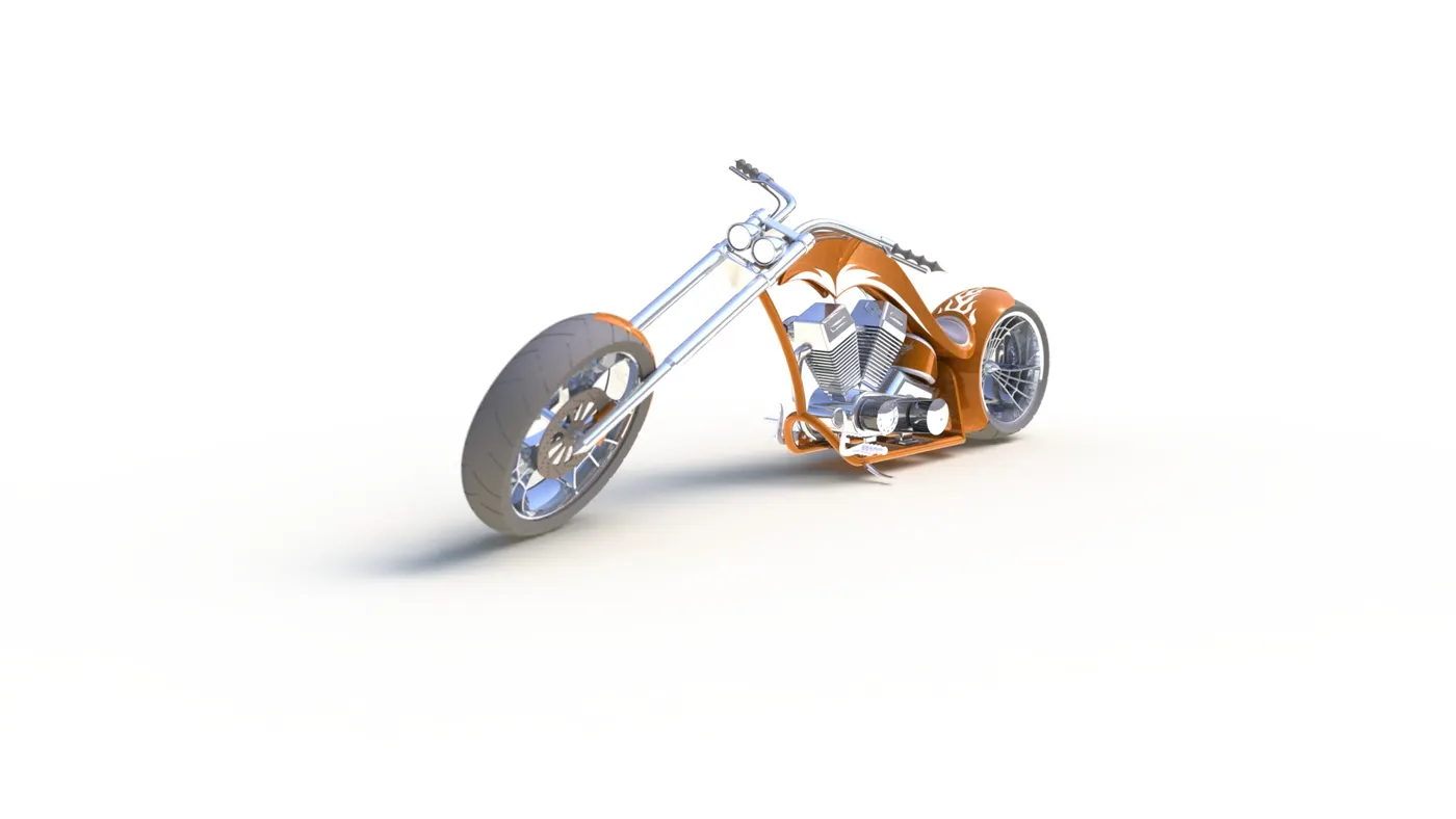
This report is an detailed explanation of the assembly of the chopper model and the rendering of the chopper .
INTRODUCTION:
in this report every component design is included and the design methodlogy is written with brief images to explain .The assembly of chopper model and the rendering of the model using the photoview 360.
DESIGN METHODLOGY OF THE CHOPPER MODEL
- MODELLING
- ASSEMBLY
- RENDERING
MODELLING
components modelled :
- transmission belt
- chain
- kickstand
- front fender
- rear fender
- front fork
- front wheel
- rear wheel
- gas tank
- oil tank
- engine
- chassis
1.TRANSMISSION BELT :
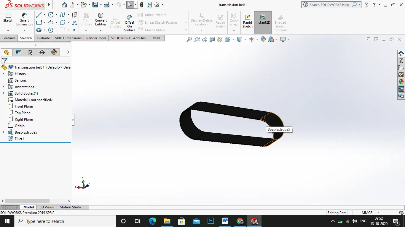
the transmission belt a component of the chopper model ,which is connected in engine to transmit power from the crank wheel to the sprocket area .
process:
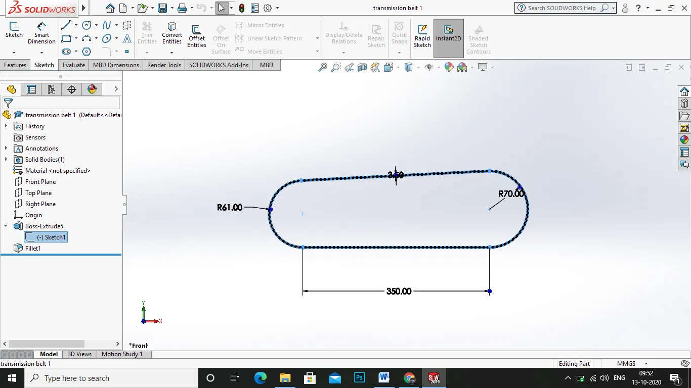
1.select the plane which is best i chose front plane and sketch in it
2.next sketch the required line with dimension in mm
- use the smart dimension tool to dimension it for fully defined sketch
- next exit skectch and select the sketch .
- use the extrude boss/bass in menu command in features tab
6.use 180mm of extrude in one direction.
7.apply the appearance of the belt to matte rubber then save the file.
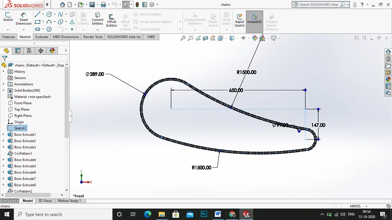
2.CHAIN:
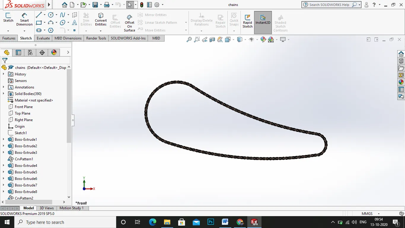
the chain is a componenet of the chopper model , which is the drive train of the bike connecs the engine and the rear wheel.
process:
1.first select the required plane to start the sketch and sketch in it
2.draw the offset line of the chain pathway to get clear idea of the insertion.
- daw the roller the connects the chain pallet .
- a cylindrical roller bead with the required dimension .
- use the extruded bose /bass option in the feature tab
- apply the amount of extrude.
- next select the frontpalne and draw the chain connecting pallet
- using the circle and arc option the pallet is drawn .
9.next use the extrude option .
- then save the pallets to a file to insert wherever required .
11.next insert the pallets from file to the sketch and start inserting them in the drawn path as two roller and a pallets connected one by one as like a chain and select the inserted parts and click linear pattern in the features tab menu .
12.then do the same as the path fills up like an exact chain.
13.next use the mirror entities in the features tab and select the whole inserted parts and in the mirror entities select the plane about front plane and click ok..
3.FRONT FENDER:
it is used to protect the engine and the rider from splashing of dust and the water . which is located in the front fork and front wheel.
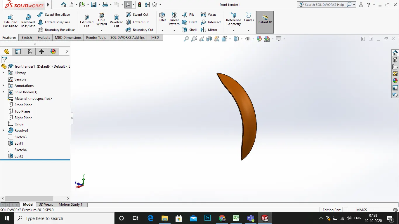
PROCESS:
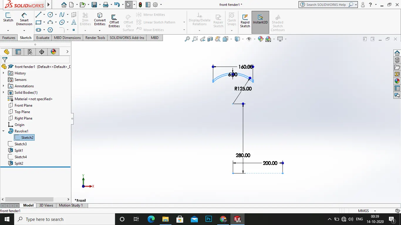
1.To design this front fender select the required plane as front plane and start the sketch.
- draw a reference line from the origin as construction line . then draw a 3point arc as closed one and mark the required dimension .
- next use the revolve boss/base option in the feature tab select the rotation of axis about the centre reference plane . click ok
- then a revolve is made .
- then split the revolve the by half using the split tool option in the insert>features >split
- then select the right plane and start sketch . draw a v shaped cut in the fender to give a nice look of it ,
7.the iuse the split option in the features click the drawn area ok.
- now do as same as in the lower end of the fender.
- apply the appearance>painted>car>siena .
10.save the file .
4.REAR FENDER:
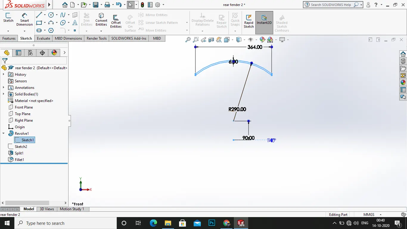
it is used to protect the rider from splashing of water and soil into him . it is located in rear of choper model.
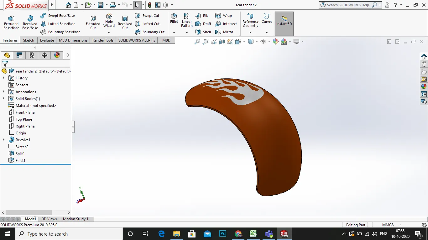
process:
1.select the required plane and start the sketch
- draw the reference line from origin .
3.draw the required sketch for the revolve .
- using the revolve boss/base in the features tab .
- select the rotation of axis as centre axis.
- the split the revolve by half using the split option .
7.select the another plane to make the fender split as u shaped .
- us eth split option in the features tab or insert>features>split.
- use the option and click ok
- apply the appearance as siena .
5.KICK STAND:
it is used to resist the total weight of the bike when restung in the ground.it is a steel machine part.
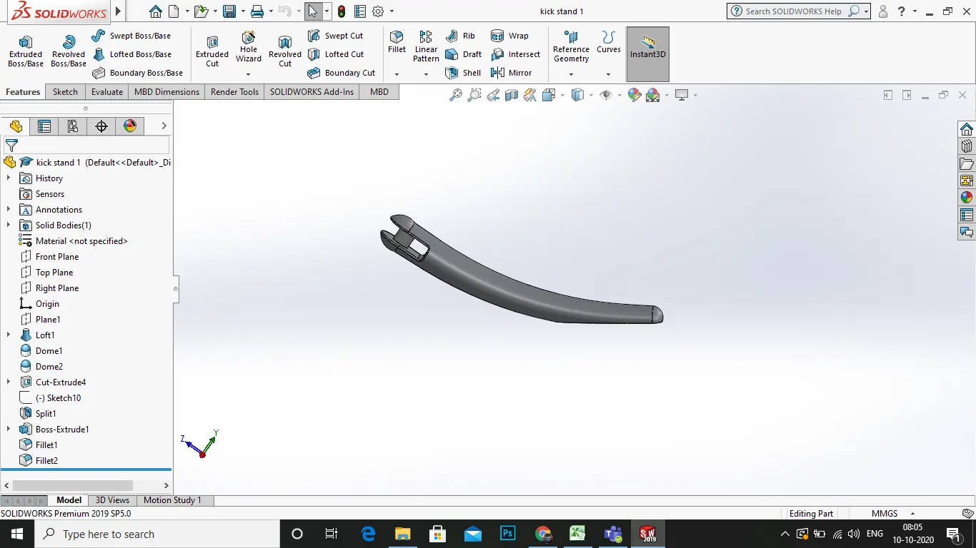
PROCESS:
- to start the design first select the required plane and start a sketch.
- from origin draw a constructiuon line upwards.
3.in the origin draw a eclipse to a value.
4.next exit sketch and selct another plane and draw a spline from the centre point of the eclipse to a point .
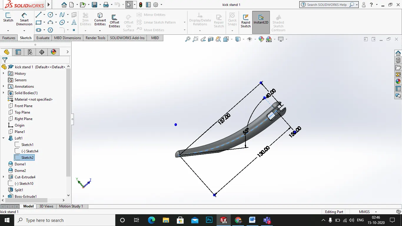
5.next in the features tab reference geometry > plane select the option
6.in the first reference select the spline and in the second reference select the end of spline.
7.now click ok and exit the sketch and on the plane start a new sketch.
- on the plane draw a eclipse of value and use the swept boss/base in features option.
9.use the option to get a nice sweep.
10.now aplly dome at the each end of the sweep.
11.now appl the appearance as polished aluminium.
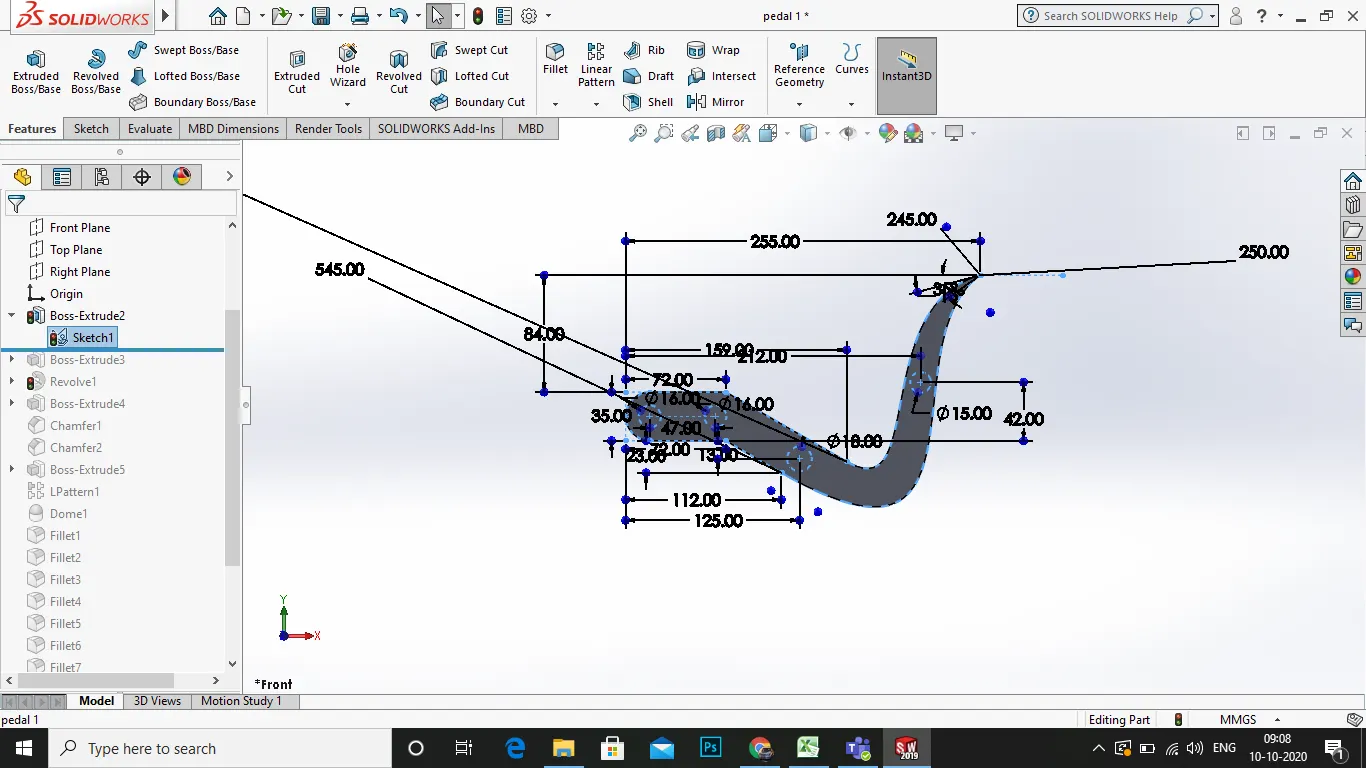
6.PEDAL:
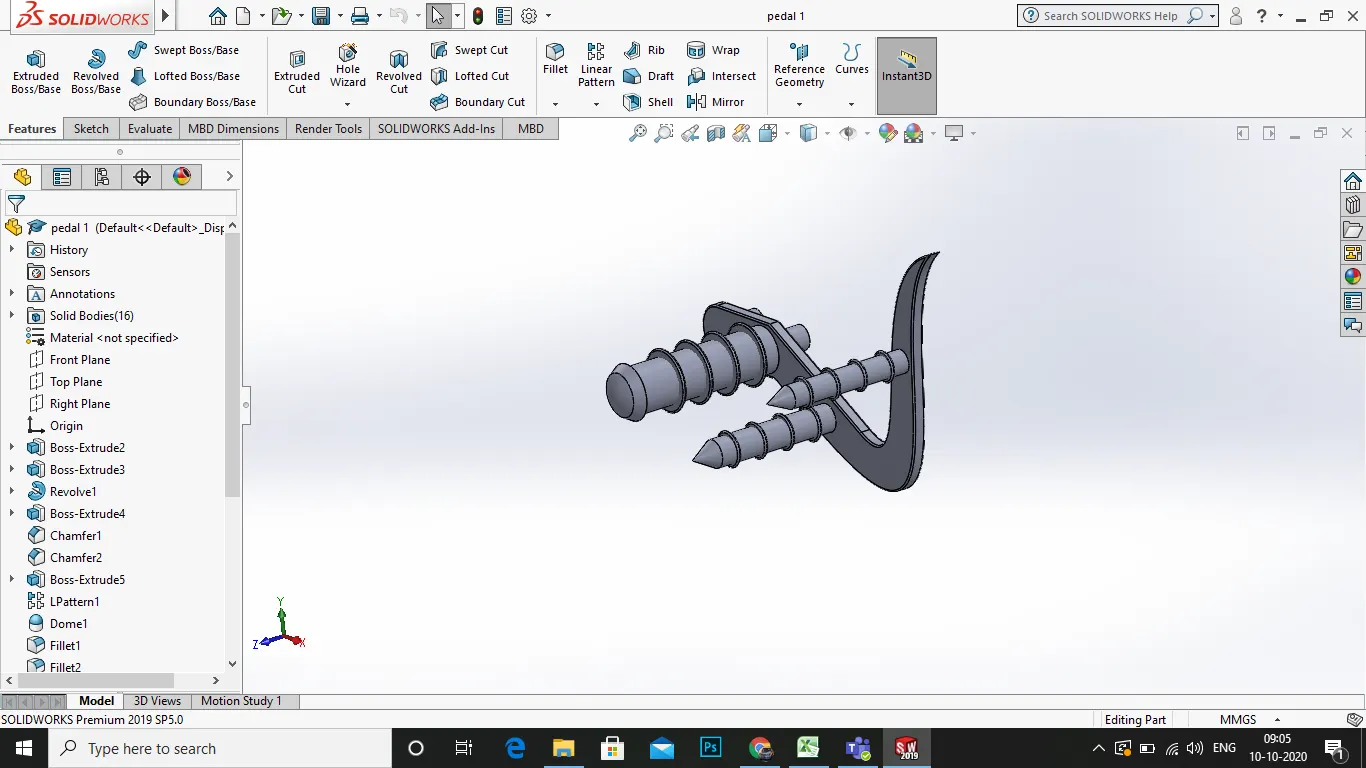
it is a part of the choper which is used to rest the leg on the pedal and to drive and apply the rear brake. actions.
PROCESS:
1.slect the required plane as frontplane and start a new sketch.
2.draw a number of splines as shown in the pic
3.as the sketch drawn make it extrude to a value in the features tab.
4.next draw a new sketch on the face of the pedal a circle and exturde it as same as two side by side .
5.and start a new sketch in the other side of the pedal.
- draw a revolve and exturde it .
- next draw a ring chamfer for grip in the revolve and pattern it .
- apply some fillets in the edges of the pedal of 3mm.
- apply the appearance as polished aluminium.
7.GAS TANK:
a gas tank is used to store the gasoline for the choper model for the combustion purpose,it is hallow gas tonk with shell.
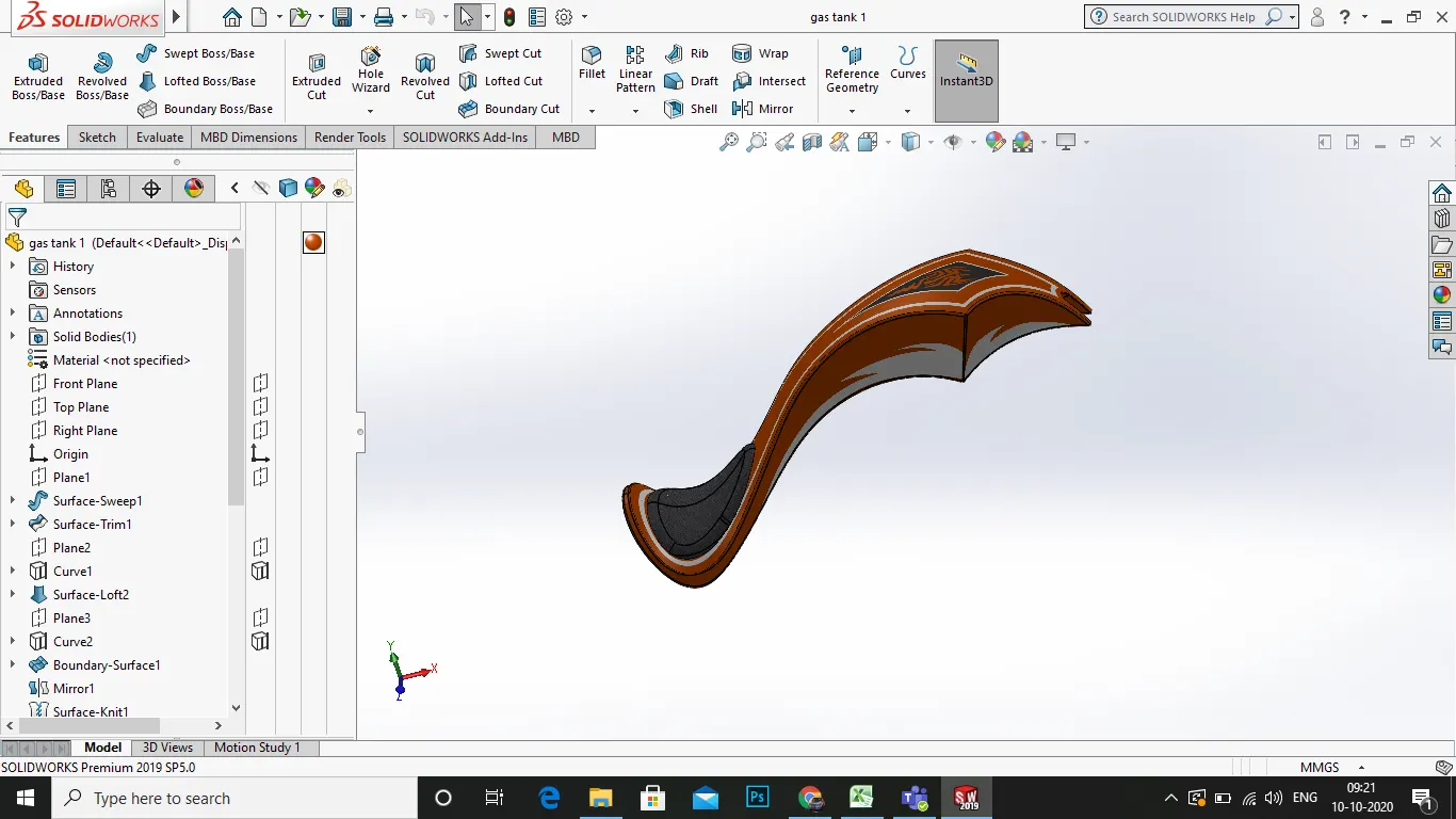
process:
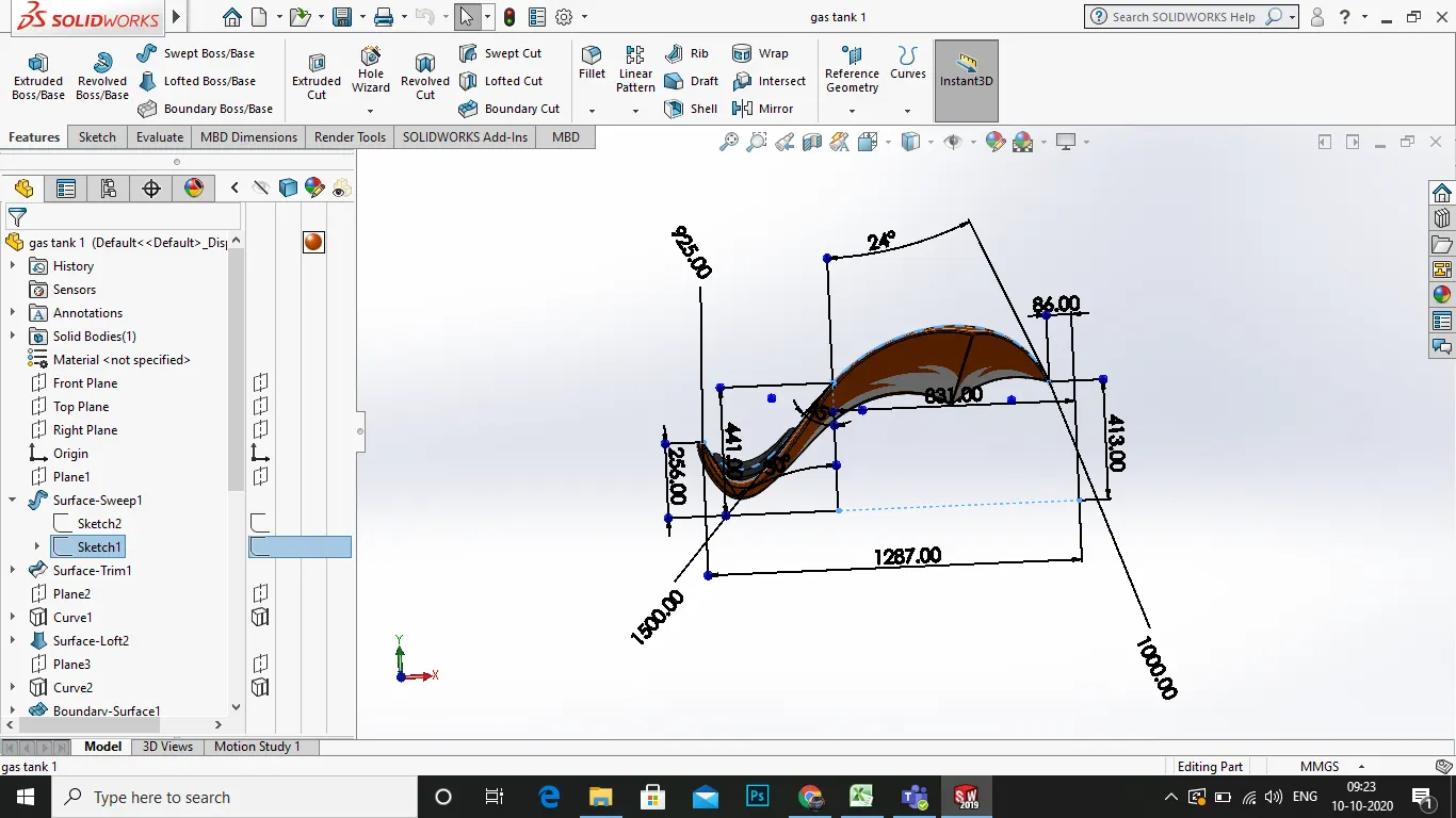
1.select a new plane as front plane and start a new sketch.
2.insert picture of choper blueprint using tools>sketch tools> insert picture.
3.using the blueprint draw a first spline in the gas tank for porjection of curve.
4.then draw the splines and mark the dimensions.
- next on the top plane draw a new sketch with arc and splines .as ashown in the picture .
6.next start a new sketch on the top plane and give the dimension for the perfect curvature .
7.nex exit the sketch and select the sketch and select convert entities and make the curve for gas tank .
8.using the surface extrude make the surface pattern .
9.next the mirror the components by front plane on other side.
10.now use the surface exturde in under the gas tank for a closed tank for shell operation.
11.on the right plane starta sketch and use a plane to start a lofted boss.
12.on the plane draw a circle and use lofted boss and use lofted cut in the tank for the mating of chassis in the under tank.
finally on the top plane of the tank use the projcetion of curve by selecting the upper cowl of seat and extude it upwards and cap the end .
- finally apply the appearance for the gas tank as siena car painted, and the apppearance for seat as black cloth.
15 . save the file .
8.FRONT WHEEL:
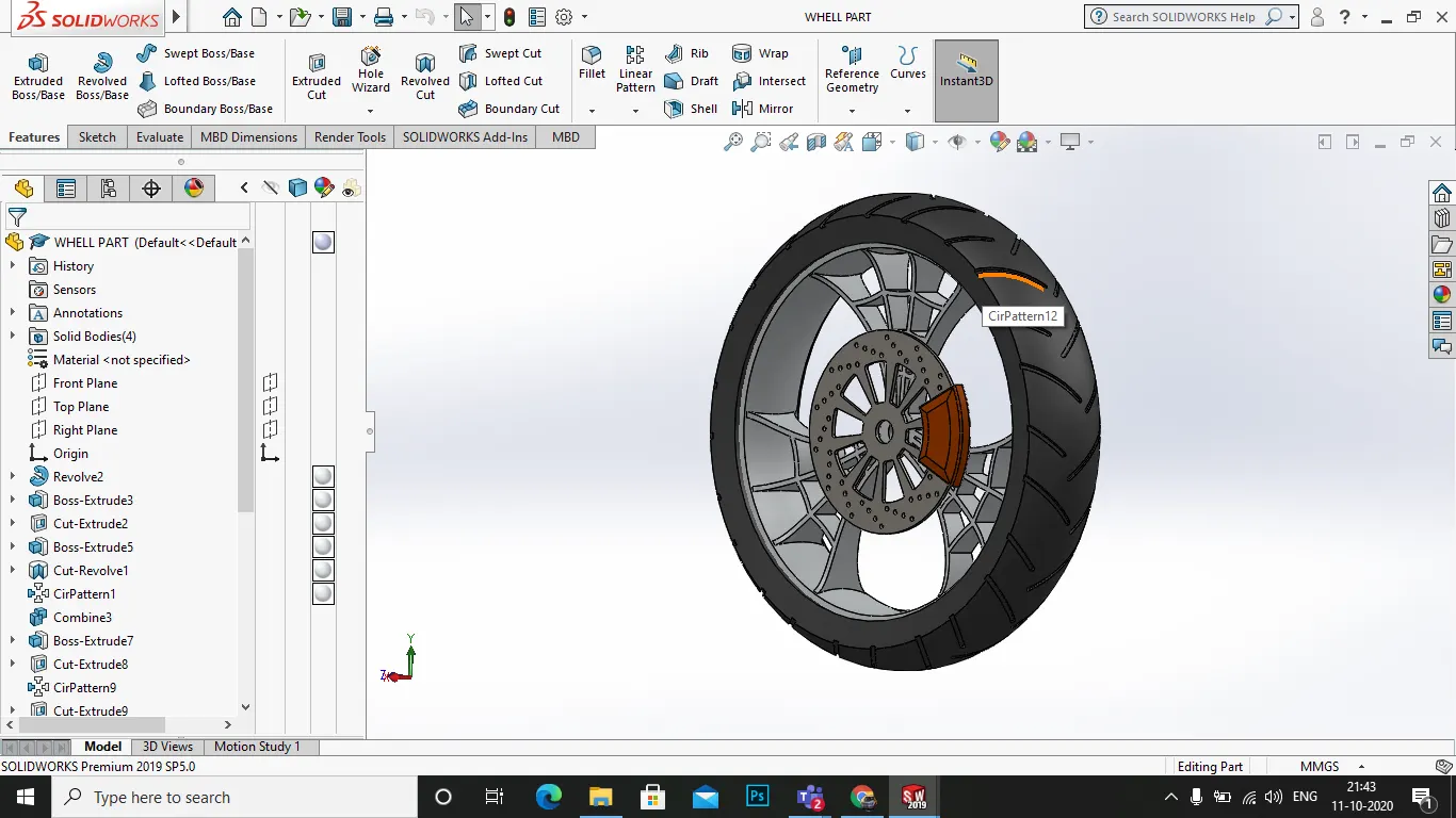
process:
- 1. select the plane as front plane and start a new sketch ,
- now draw the sketch for the revolve for the wheel rim as shown in the pic .
- then after the sketch use extrude boss/base it .
4.then draw the sketch for the rims and the cut extrude for it then use the extrude boss/base it
- after that circular pattern the rim design .
- after that draw the sketch for the tyre and revolve it by features tab>revolve boss/base.
- then draw the sketches required for the cut pattern for the tyre desgin .
- then circular pattern the cut grooves
9.the draw the sketches for the disc and extrude boss/base it
10.again draw the sketches for the disc caliper and extrude boss/base it.
11.then apply the fillets wherever required.
12 apply appearances wheel rim>polished aluminium, tyre>matte rubber , dusc caliper> siena, disc > steel.
- save the file.
9.REAR WHEEL:
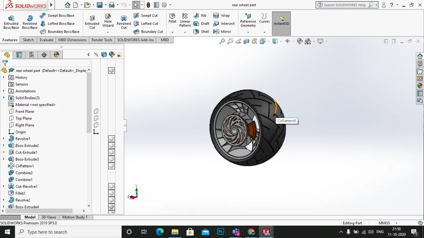
the rear wheel is also plays major role in the working of the chopper and its moves the vehicle and proveides torque.
thus it enhances the stability .
process:
- selecr the plane required and start the new sketch,mark the dimension in mm.
- dra wthe sketches for the revolve of the wheel rim.
- next after the sketch use the revolve boss/base .
- and after that draw the sketches for the rim design and apply the grooves and us ethe extruded boss/base and also use the split option.
- now select the rims drawn and circular pattern it around the revolve .
- draw the sketches for the tyre and revolve boss/base it .
- now draw the sketches for the tyre pattern and extrude cut it.
- next draw the sketch for the disc and extrude boss/base it.
9.now draw sketch for the disccaliper and extrude boss/base it and apply the fillet.
- now finally draw the sketch for the chian sprocket and extrude boss/base it .
11.now draw the sketches for the grooves in the face of the sprocket then use the extrude cut it
- now draw the sketches for the gear grooves in the sprocket and use the extrude cut it.
- now finally draw the axlefor the rear wheel .
14 now apply the appearances wheel rim > polished aluminium, tyre > matte rubber, disc> steel, disc caliper > siena, sprocket wheel> rough brass.
- then save the file.
10.OIL TANK:
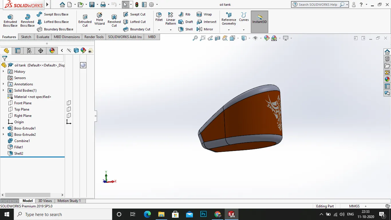
the oiltank is one of the parts of the chopper model, it's work is to store oil for the lubrication of engine and keepthe engine
in low friction level . it is located in between the below of chassis and the up of the engine transmission case.
PROCESS:
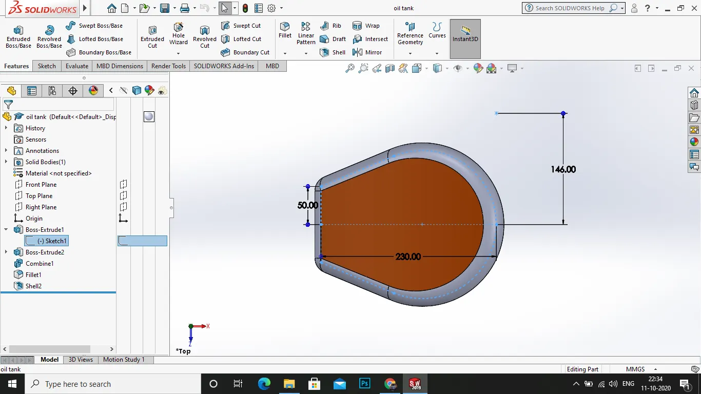
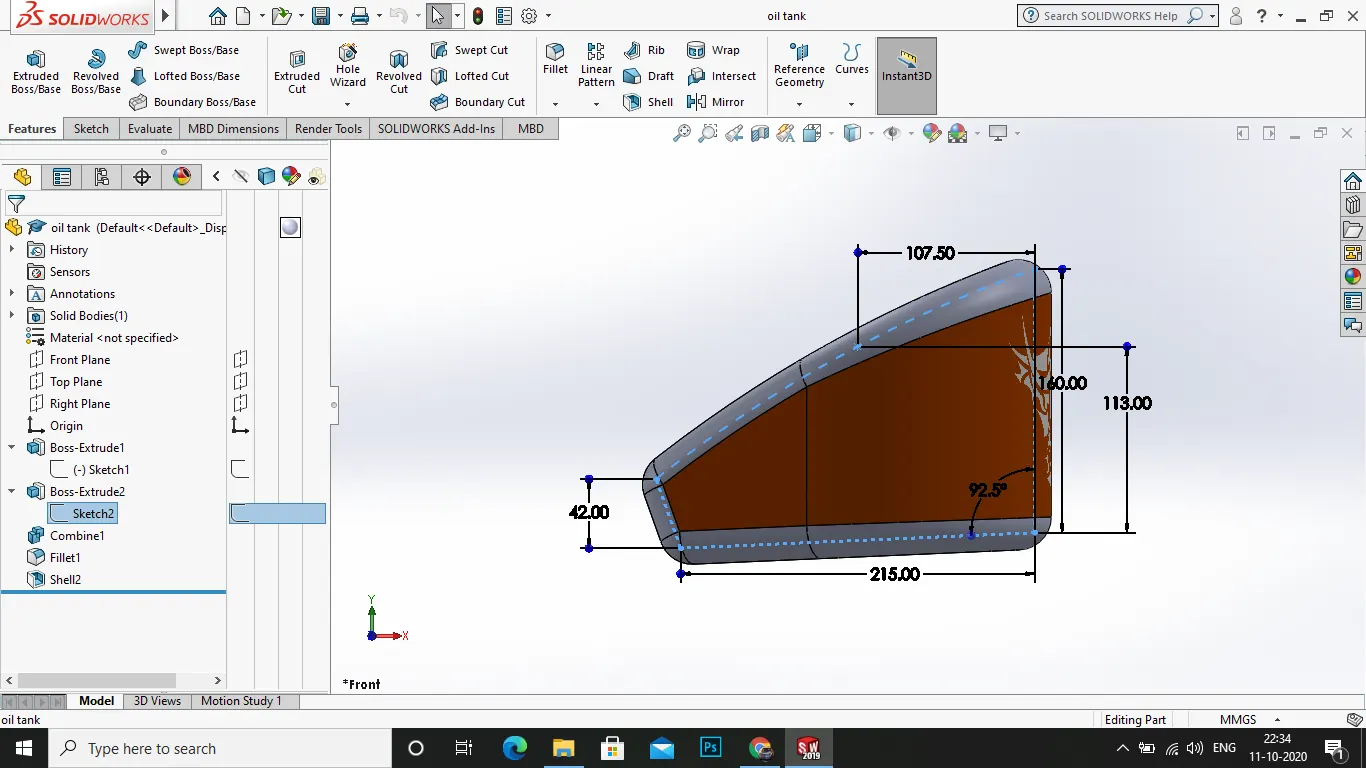
1.select the plane required and start the sketch
2.now draw the sketch for the bottom of the tank and use extrude boss/base it towards y axis .
- now draw the sketch for the wider portion of the tank and use extrude boss/base it in x axis.
- now use the combine tool in insert>features>combine.
5.in thecombine select the both boss extrudes and click ok.
- now apply the fillet in the edges .
7.now select the sheel option for 10mm in the tank.
8.apply the appearances for the oil tank as tank >siena and fillets > sheet metal.
9.save the file.
11.FRONT FORK:
The front fork is the another part of the chopper model it is used for the directional drive of the vehicle and to make turns whenever a corner or turn is needed.
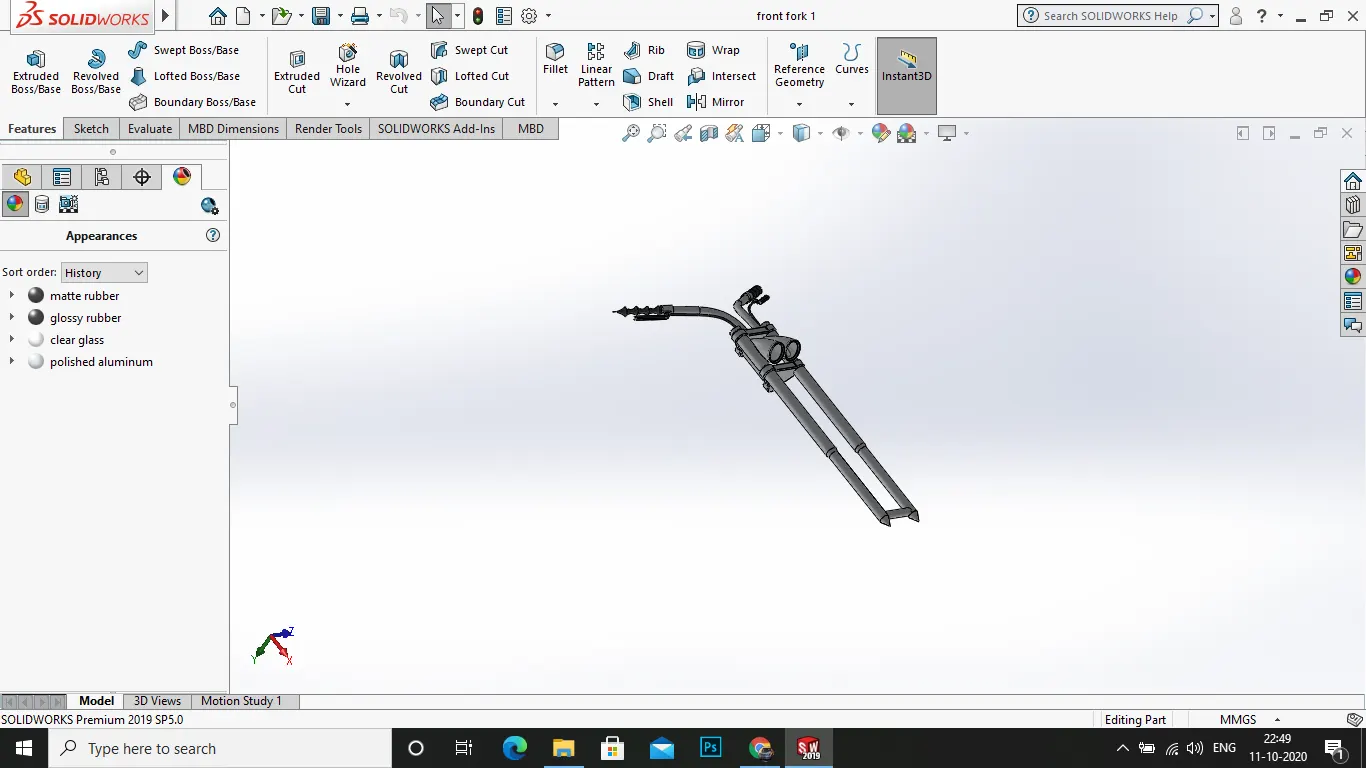
process:
1.select the plane required and start a new sketch.
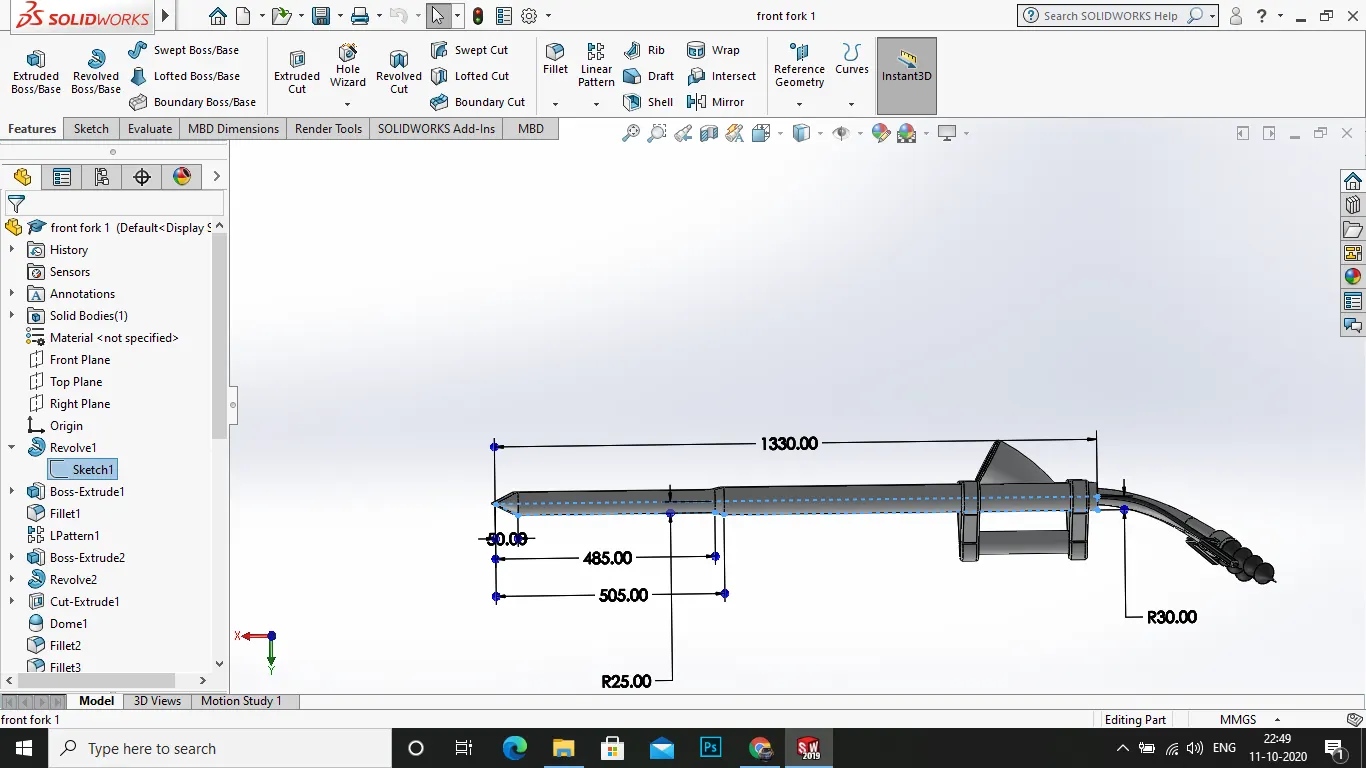
2.now draw the sketch for the front fork as shown .
3.after the sketch drawn now us ethe feature>revolve boss/base option and select the axis as rotation.
- after that draw the sketch for the upper and lower mounting plates (brackets).
- draw the mounting plate as shown and use the extrude boss/base it for a value.
6.now use the offset option in the extrude boss/base to certain mm to lower it slightly in the fork.
- now use it the same method for the lower mounting plate as shown .
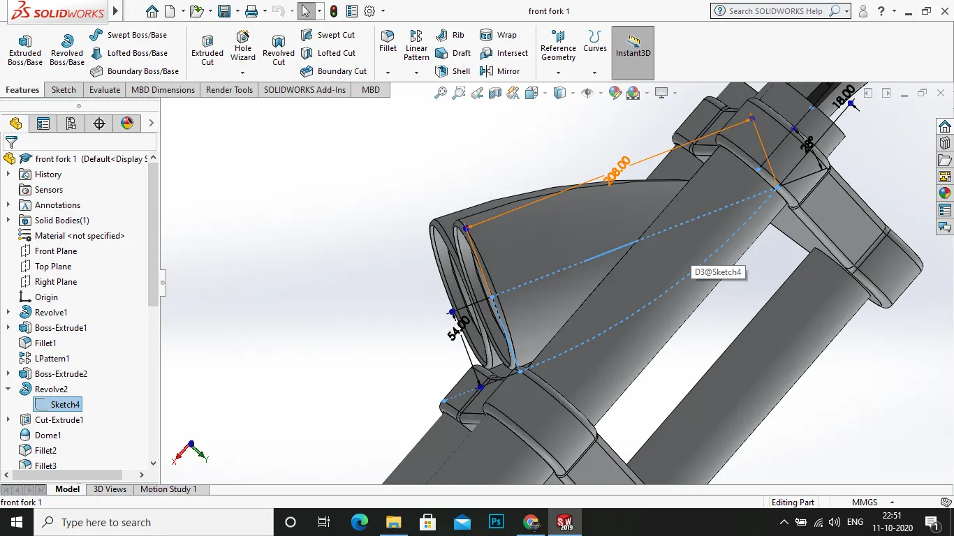
- now select the plane required for the sketch of dome lights .
- draw the sketch shown as andus eth revolve boss/base it
- in the dome light a bulb type dome has to be made so use the dome option in insert>features>dome.
- now apply the fillet wherever required
- after that a handle bar is to be made so select the face of the brcket and draw a sketch for sweep .
13 draw the sketch as shown for the sweeo of hanlde bar.
- after the sketch use the features>swept boss/baseand click merge result.
15.now draw the sketch for the hanlde grip and the brake lever.
- after that on the face of bracket draw a sketch for cable that connection the front face of the brake lever.
17 now use the swept boss/base for the sketch for a nice cable projection.
- now finally select all the components and mirror it about front plane .
- now at the lower end of the forks draw a axle that connects two forks and used as a axle for front wheel.
20.finally combine all the components
- apply the appearances as fork, handle bar , dome light> polished aluminium, lights>led>white , handle bar grip> matte rubber, brake lever > black rubber.
22.save the file .
12.ENGINE:
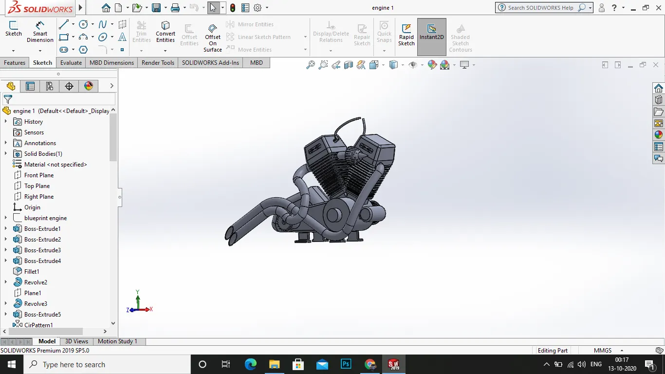
an engine is the main part of the chopper model , which is the power unit of the bike and transmits power to the wheels.
process:
1.select the plane as required and start a new sketch.
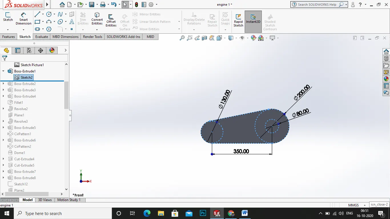
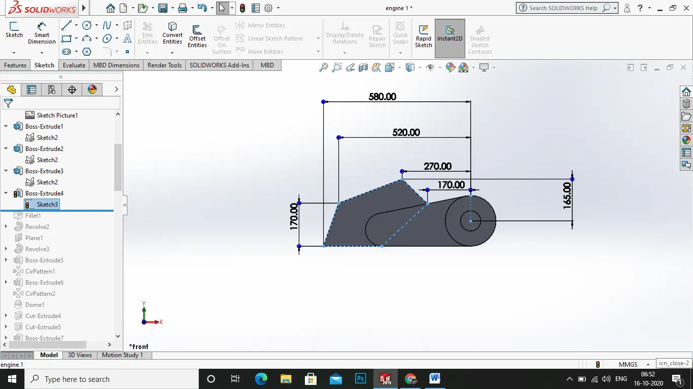
2.now draw the sketch for the transmission and crank casing area as shown.
3.when completed the sketch use the extrude boss/base it .
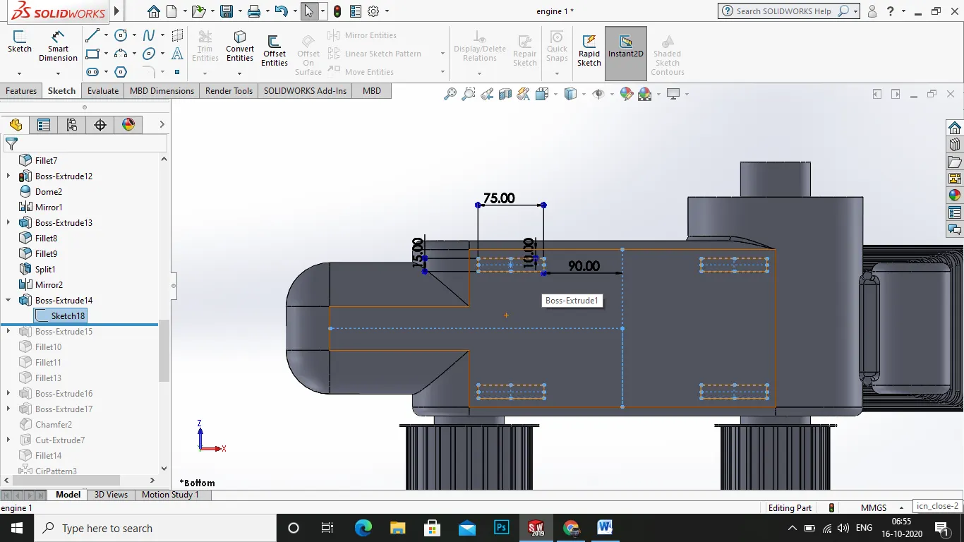
- now draw the sketch for the starter motor and extrude boss/base it.
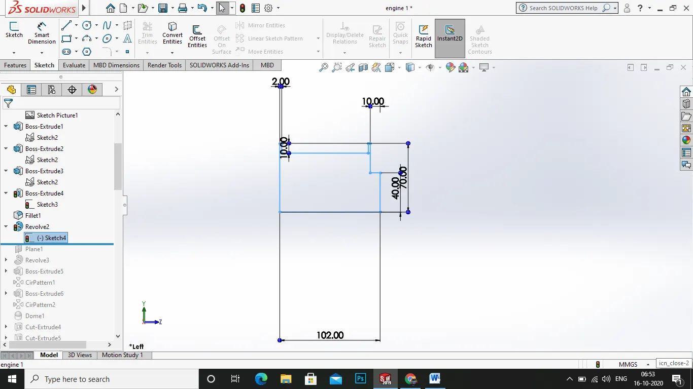
- after the feature draw the sketch for transmission belt roller , by slelcting a plane suitable and mark the dimension as per the pic .
- after that rvolve boss/base the sketch and select merge result.
- now start a new sketch for the cylinders on the top of the cylinders as shown in picture.
- now use the xtruded boss/base option and merge result .
- next draw the sketch for the grovves for fins and make it using extruded cut.
- now after the cylinder is built mirror the cylinder by the axis drawn and click ok.
- after it start a sketch for the sprocket wheel , by first sketch of extruded boss, followed by the circle extruded boss.
12.now sketch the gear grooves in the face of the boss extrude .
- next the draw the skecth for the spark plugs and extrude boss/base it.
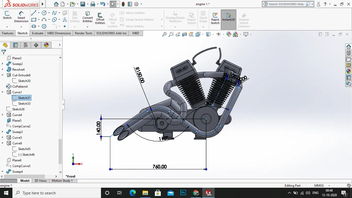
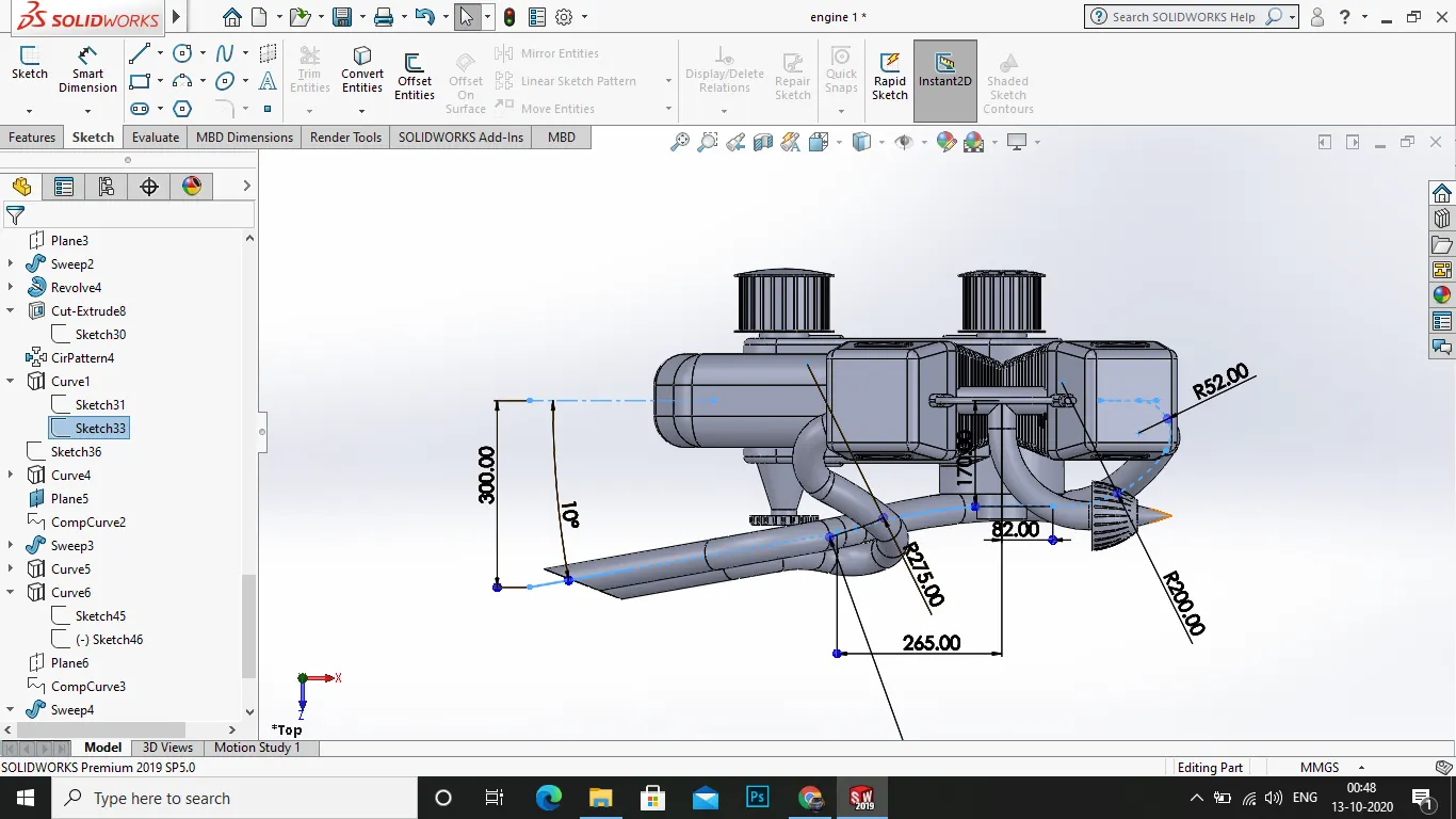
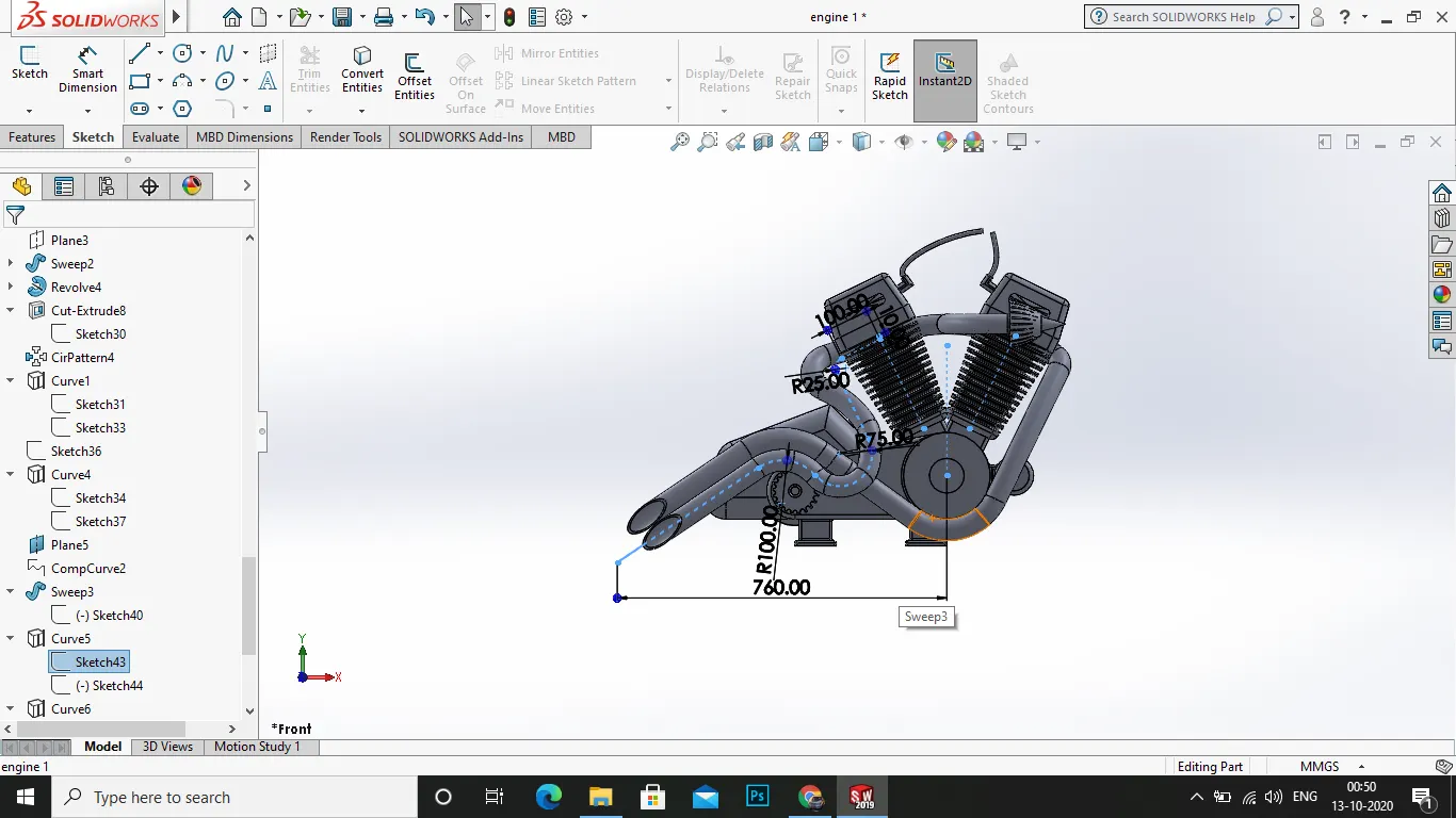
14.then finally we go on with sketch for the exhaust pipes.
- select the fornt plane and draw the sketch for the first exhaust pipe of composite curve.
- now this type of sweep requires more composite curves and projcetion curves.
17 now to start with it, draw the sketch full of curves in the path of blueprint exhaust pipeand slect the top plane and draw the curves for the exhaust pipe .
- next select the right plane and draw the path the pipe has to go.
- now using the feature>reference geometry> projection curve .
- select the two curves and a nic eprojected curve is made, now on the feature use a plane in the curve 3 a shown .
- on the plane start a new sketch and draw a circle for sweep, use the feature>swept boss/base it.
- now for the second exhaust pipe , draw the curves for the fornt plane and dra wthe curves for the top plane as shown and use the plane , and draw a circle and us ethe feature>swept boss/base .
- finally the end fthe exhaust pipe requires split for the perfect edges so draw the required cut sketch and us ethe split option.
- now apply the appearances as engine>polished aluminium.
25.save the file.
13.CHASSIS:
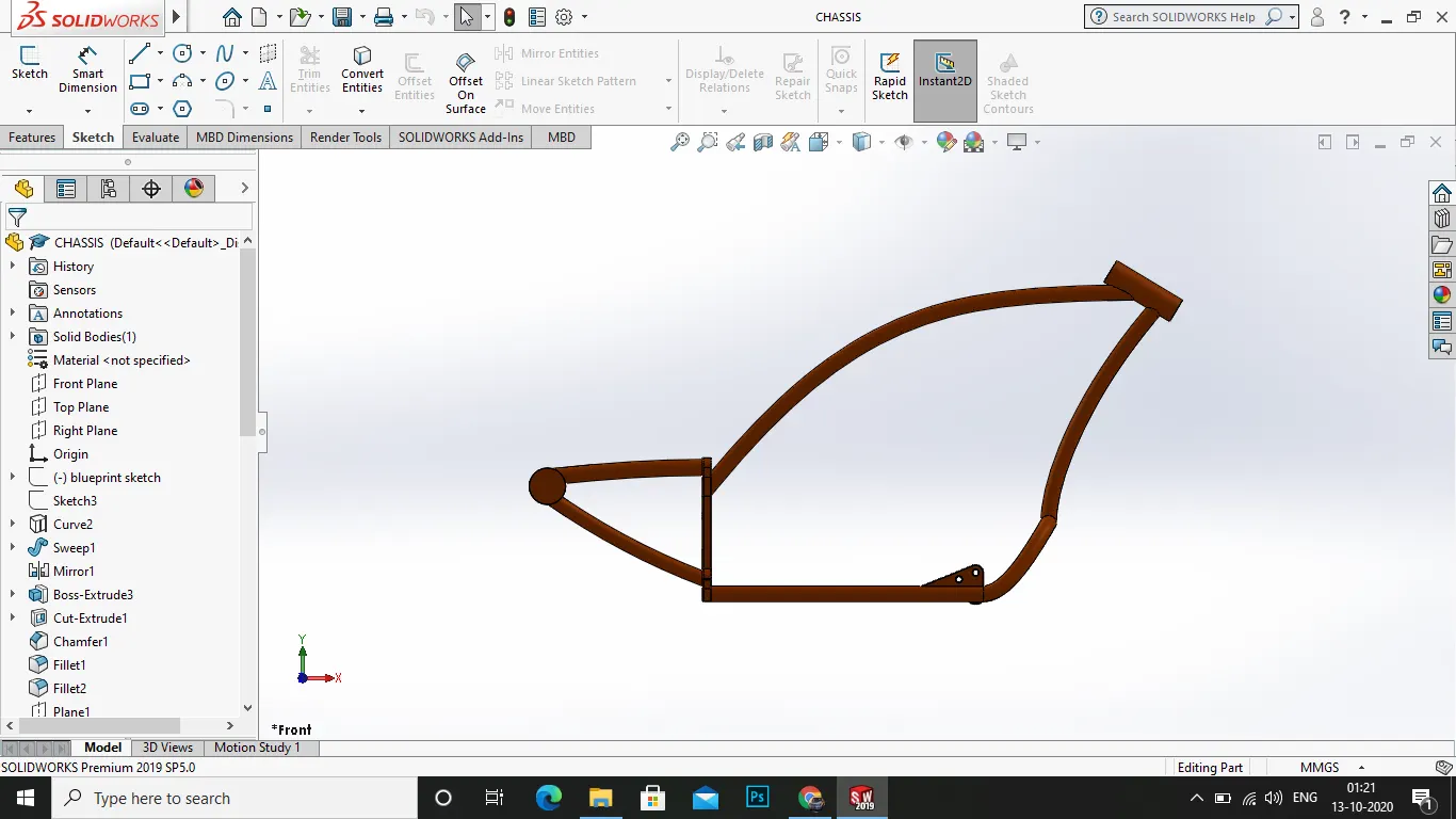
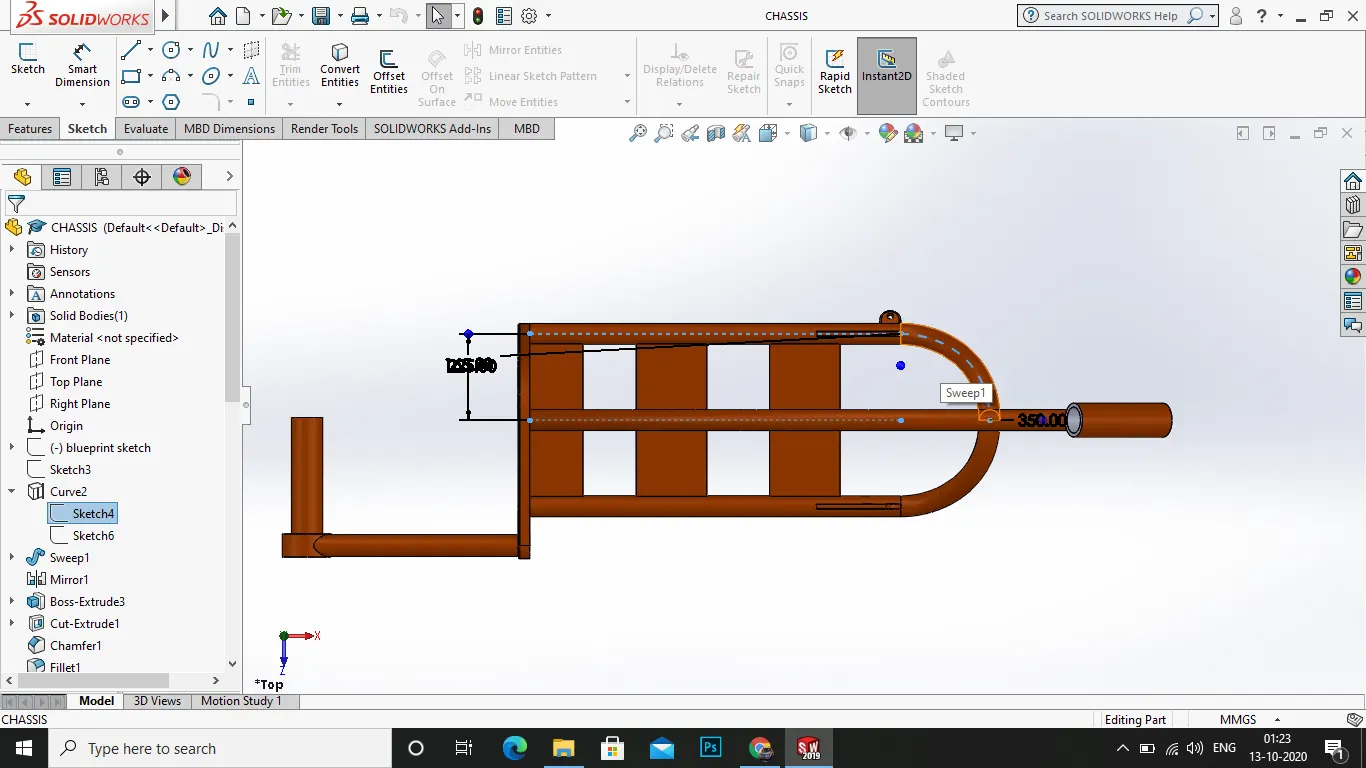
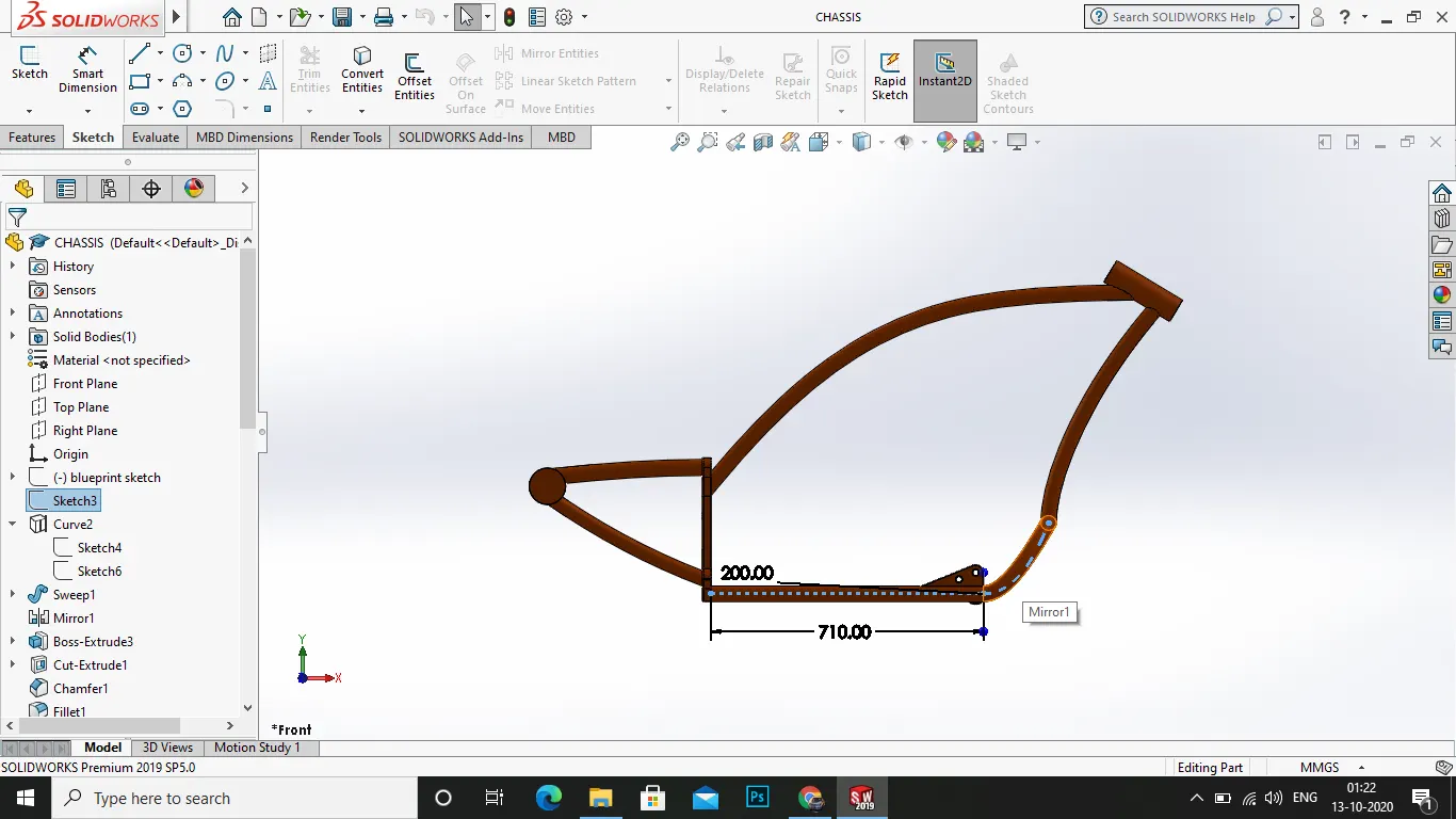
the chassis is a the bone of the choper model and it is the casing and connecor of various parts and components .
process:
1.select the plane as required and start a new sketch .
2.for the design insert the picture of blueprint.
- now start a sketch for the lower chase pipes as shown dimension and draw another curves in the top plane for the projection of curves .
4.now apply a new plane for the end of the sketch line and draw a circle valued for the swept boss/base.
5.and mirror the sketches across the front plane.
6.now sketch back plate that connects the chassis and the rear arm for the rear wheel.
7.now after the sketch is complete extrude boss/base it.
8.next draw the sketch for the extrude cut in it.
- bow apply the fillet around,in,on it.
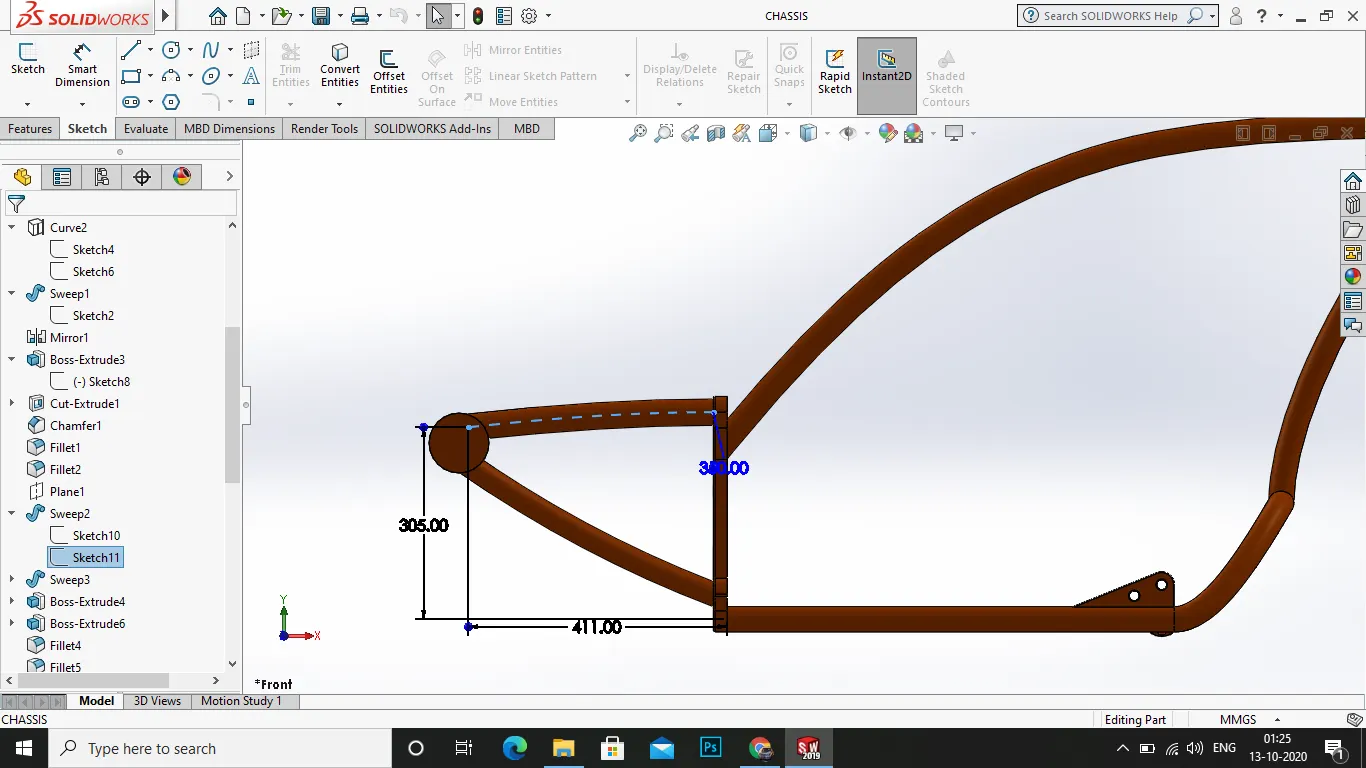
- now draw the sketch for the rear arm upper one and use the swept boss/base it .
- next draw the sketch for the rear arm lower end and use the swept boss/base it.
12.after that draw a circle for the rear axle that connects the two arms of rear.
- now extrude boss of a circle from the face of the axle .
- finally to the upper chase , draw the sketck for the upper center tube curves and at the end of the curve applya plane and on the plane draw a new sketch and use the swept boss/base it.
- after that on the lower chase the cicrle between the two pipe joint make the circle intersection curve and and draw the sketch connecting from the edge of the intersected curve and the upper end near to the upper chase .
- now apply a new plane at the end of the curve in the upper region, and use the swept boss/base it.
17 finally draw the bracket pipe that connects two chassy pipe and the axis of rotation for the front fork.
- draw the sketch for the revolve and use the revolve boss/base it .
- now select the front plane for the sketch of the engine mounting plate .
- draw the sketch as shown and use the extrude boss/base it.
- now dra wthe sketch for the pedal mounting at the fornt end .
- draw as shown in the picture and use extrude boss/base it.
- now finally draw the sketch for the mounting of the kick stand, and extrude boss/base it and use the 10mm randius fillet for the mounting revolve.
- apply the appearences as siena to the whole chassis.
25.save the file.
ASSEMBLY
PROCESS:
- first open solidworks and click new option in toolbar and select assembly part and start working
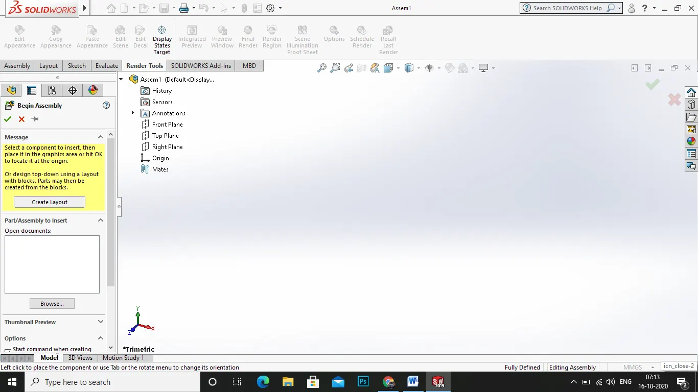
- on the left column u could see a features of begin assembly and insert components one by one .
- first insert the chassis which is the main part to mate everything and begin the assembly .
- now inseert the chassis and click ok.
- next on the features bar select mate option . and in the mate option there will be two options of mate surface 1 and surface 2 .
- and next select the front plane of the part an dthe front plane of the sketch, under the tab there will be multiple options like coincident, distance, mate, angular , perpendicluar.
- just use the coincident option.
- now select the option and click ok you could see the two planes were exactly the same when you click .
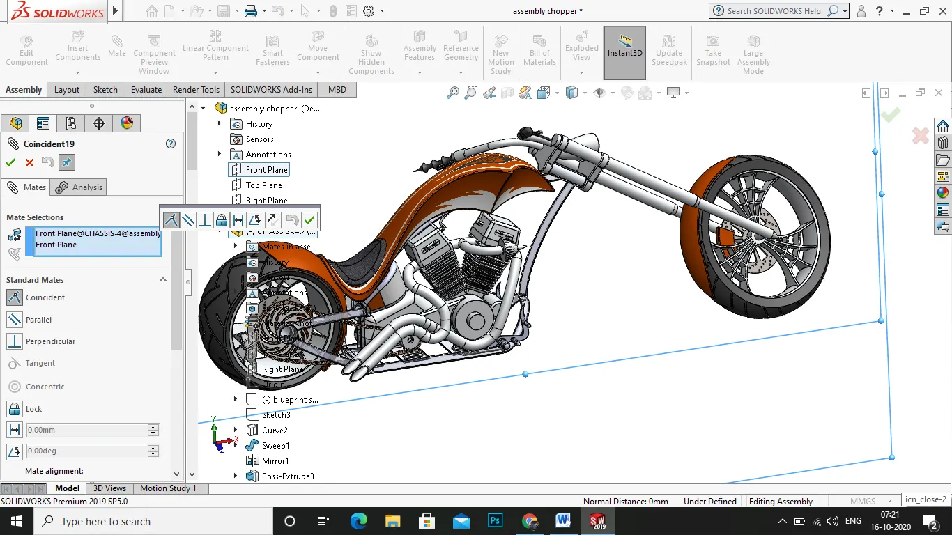
- now you could see the image that the planes are matching and right click on the part and select the option float and make sure it rotates or moves , and then agian right click it and select the fix option to be stable .
- next insert the engine part . and use the mate option and select the fornt plane and the front plane of engine and mate them, next select the bottom of the engine and the top of the engine moutning plate , and select the coincindent option and click ok.
- next right click the chassis and float it make sure it floats and agian click to fix.
- next insert the pedal by using mate select the back face of the pedal and the front face of pedal mount in the chassis and click coincident option inthe mating tab.
- make sure it floats with the chassis and fix again.
- next use the mirror option in the features tab to mirror the pedal about tfornt plane to the next side.
- next insert the rear wheel by using the mate option and select the fornt plane of the chassis and the right plane of the wheel and click parallel and click ok.
- and select the axle of the rear wheel and the axle of the rear chassis select the concentric.
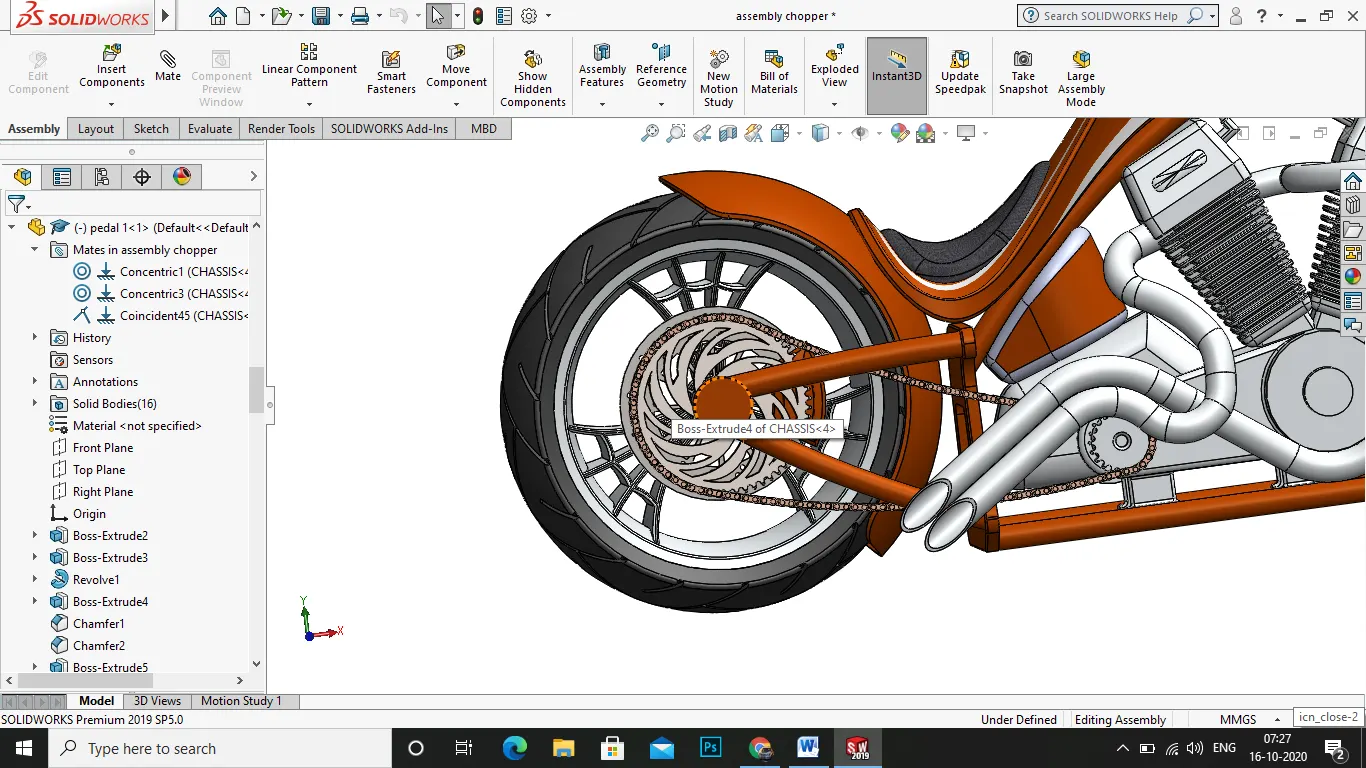
- next insert the chain component by mate option and select the gear grrove of the engine and the smaller size of the chain make coincident and select the gear groove of the rear wheel and the bigger size of the chain make coincident.
- next insert the front fork aby using the mate option, and select the fork rolling extrude and the chassis fork revolve and make coincident and again use the mate option and select the front plane of the chassis and the front plane of the front fork and make them parallel.
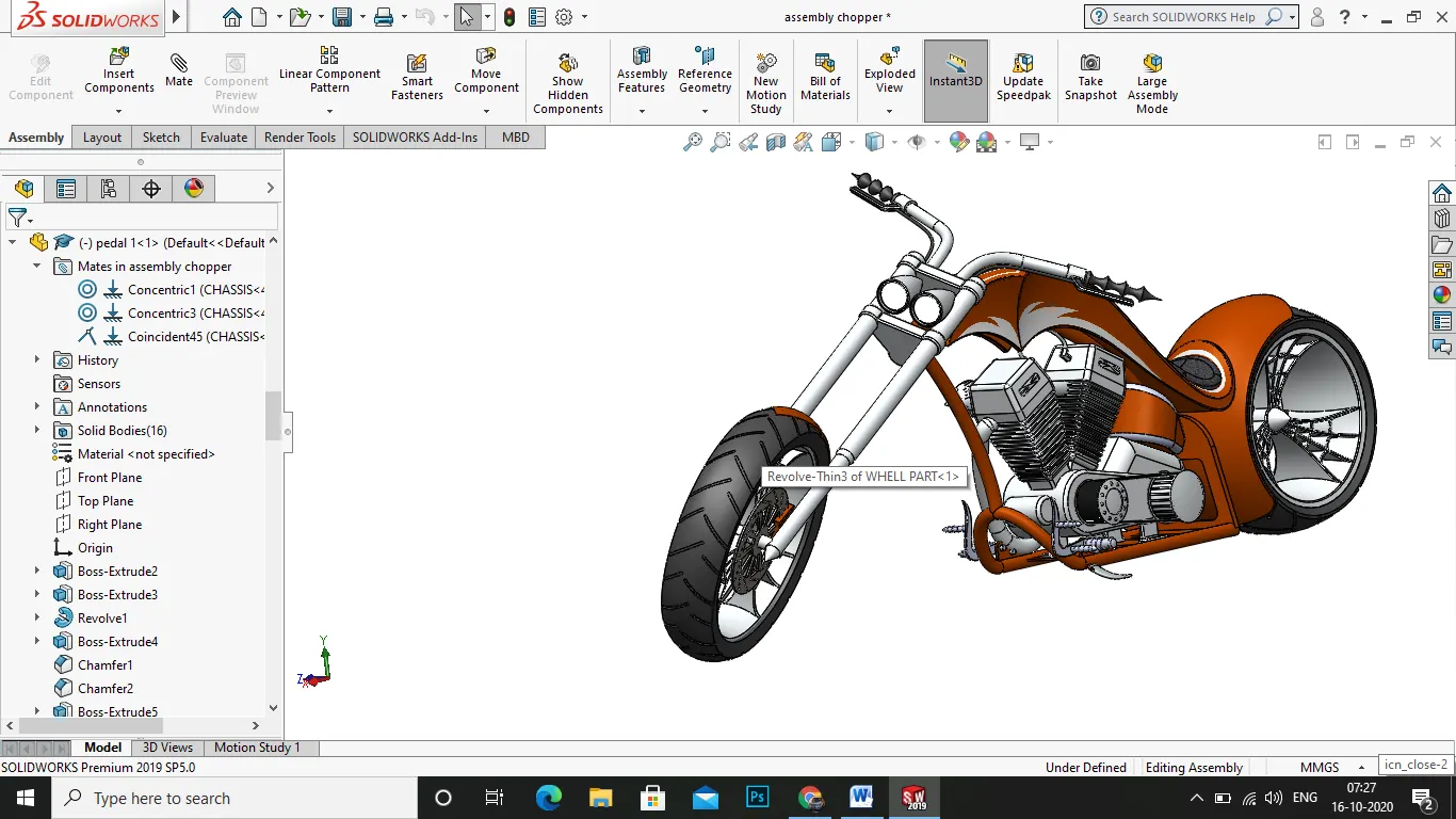
- next insert the fornt wheel using the mate option and mate the front plane of the chassis and the right plane of the wheel and make them parallel.
- next use the mate option again and select the axle of the front fork and the hallow revolve of the front wheel and make them concentric.
- nex insert the gas tank by using the mate option and mate the front plane of the gas tank and select the plane 1 of the front forkand make then parallel, again use the mate option and select the coincident option and mate the top plane of the gas tank and top plane of the chassis mate them . as you could see a nice mate over there.
- next insert the fender of the wheel of both front and rear by using the mate option in features tab mate the outer circle of the wheel and the arc of the fender and make them concentric.
- next insert the oil tank by using the mate option, mate the bottom face of the oil tank and the top face of the engine transmission case and mate them .
- next finally select the front fork for making angular mate of the fornt fork for a nice look in the environment .
- use the mate option in the mate select the advanced mate and tilt the fornt fork manually to your wish and adjut the angle it has to and slect ok and again use the mate and select the front plane of the chassis and the right plane of the fornt wheel make them parallel when you suppress the paralle mate of the fornt wheelturn the front fork and use agian the unsuppress it wille asily turns to straight .
- next insert the kick stand by mate option mate the insert circle face of the kick stand and inner face of the mounting plate in chassis make them concentric and click ok. finally you could see a nice assembly of the chopper model.
- then save the file.
RENDERING
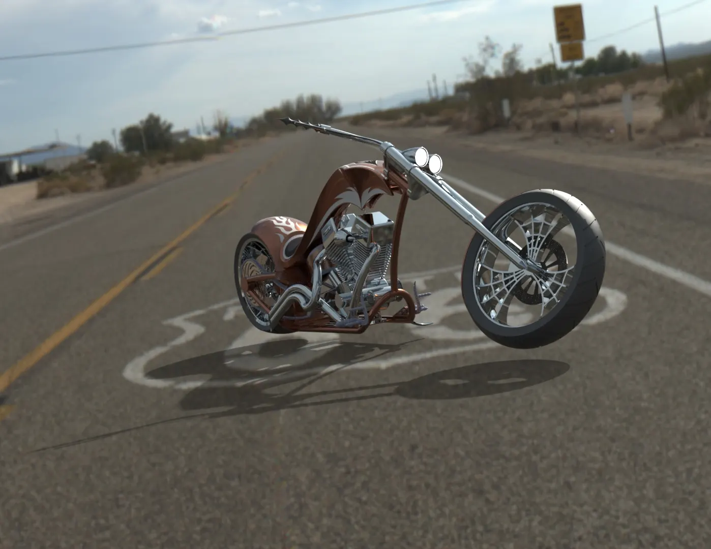
PROCESS:
the rendering part is the outmost and realtime working one which is the final part of designing this chopper model, as
this includes various option of animation, vfx, environment settings, studio scenes. etc.
- firt open the solidworks visualize 2019 in the desktop and start the new project.
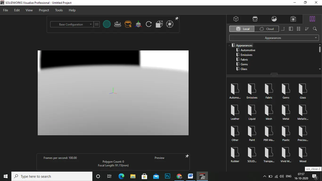
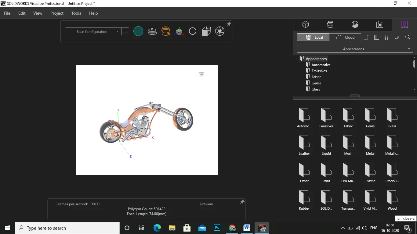
- now in the file select import part and import the assembly of chopper file you saved.
- then in the right corner you could see five options , the apperances, environment, camera, preferences, decals.
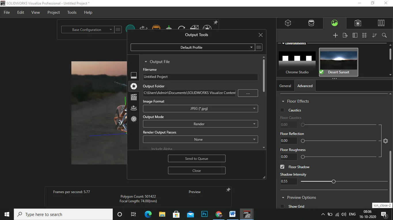
- select the environment as whatever you required i used the desert sunlight and use the background as environment.
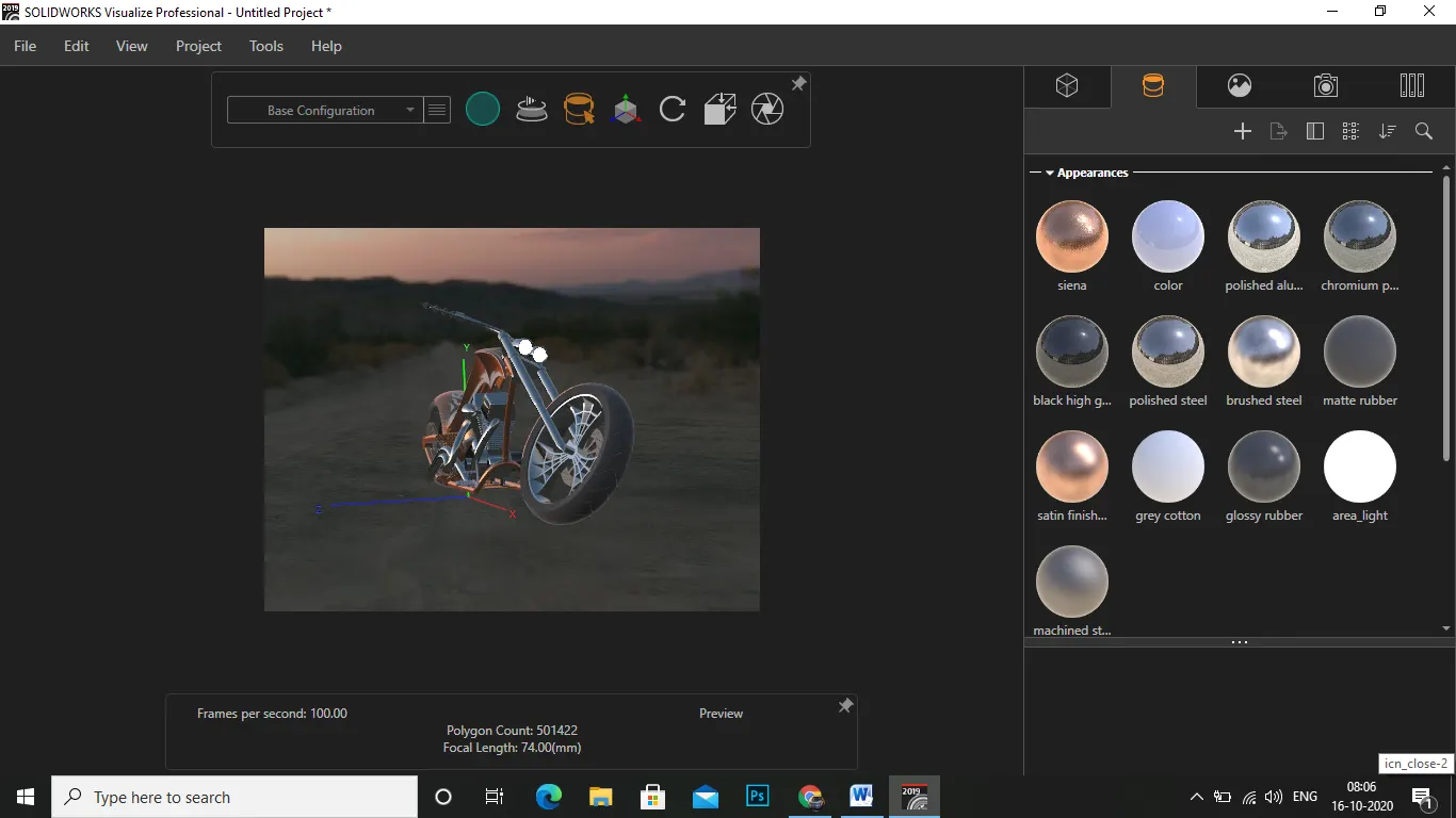
- apply the more detailed appearences to the parts of reflecting parts slect the polish type you needed.
- then use the camera option to set up the camera where the picture set ups and what the final render look like up.
- next in the top you could see some option like output render, move picture , rotate the picture .
- use the output render and select the output as jpeg or png netwrok.
- on the graphics select the cpu or whatever you have the type of system.
- next in the section of pass .use the value 1000 or 600 whatever the time you have based on your system graphics and select the option accurat eor fast or slow of render speed.
- then finally click ok and then some time after a nice final rendered output appears .
- next save the file .
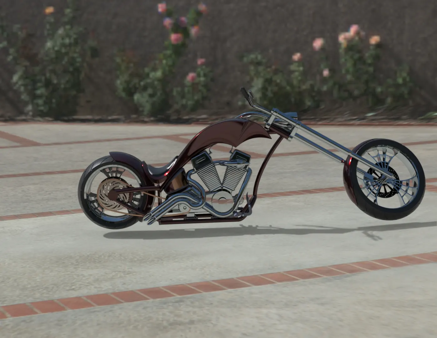
side view
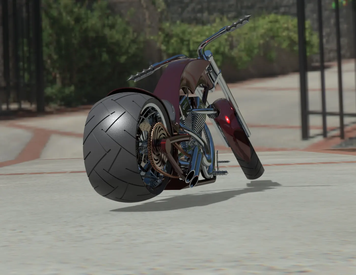
rear view
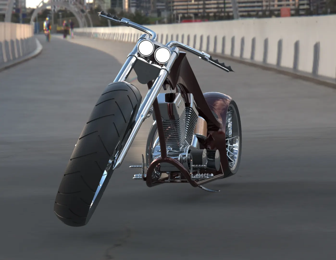
front view
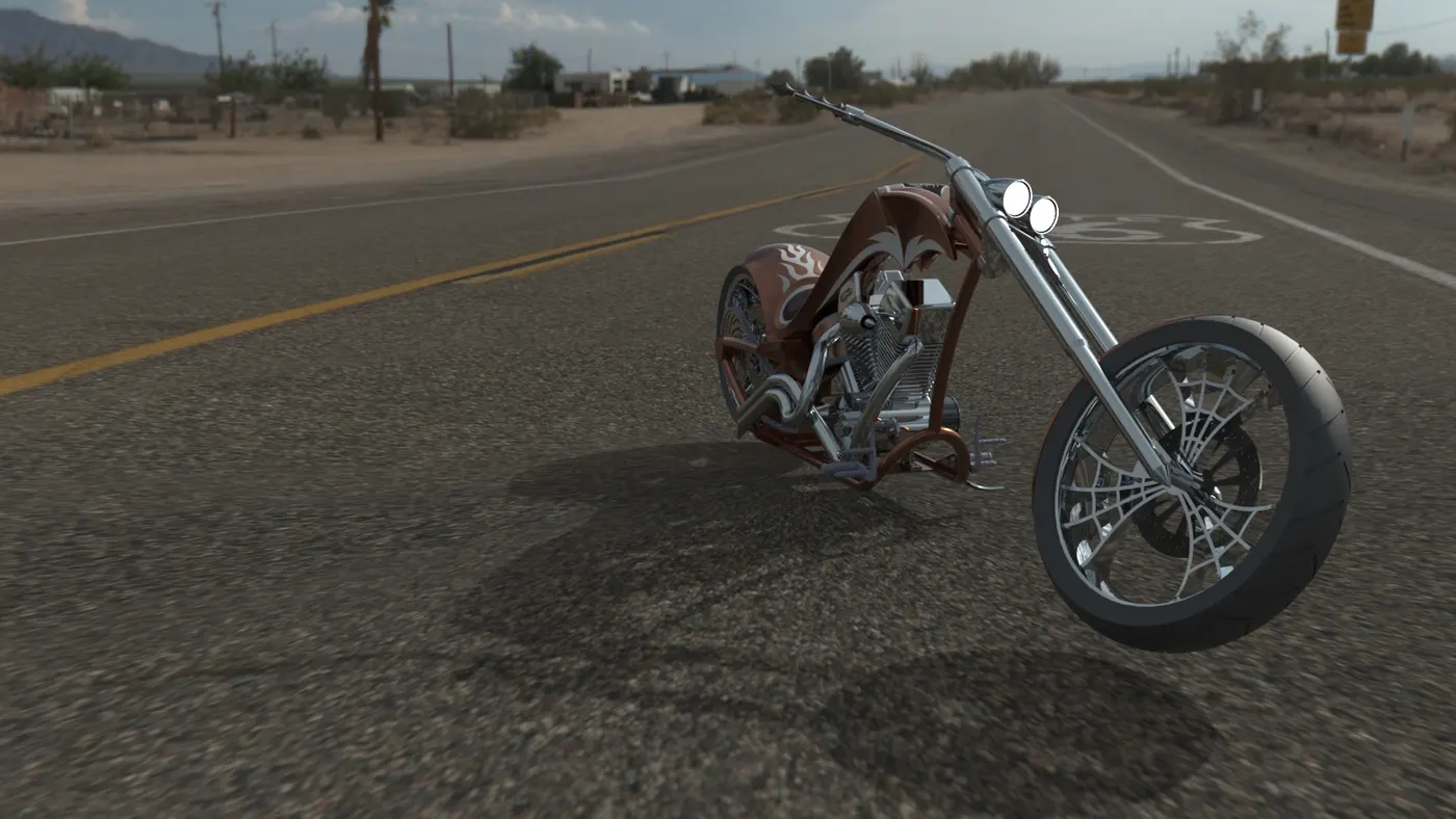
isometric view
CONCLUSION:
AS THIS REPORT IS TYPED BASED ON THE FEATURES AND THE TOOLS I LEARNT AND THE WAY IT HAS TO BE DONE , THIS DETAILED REPORT HAS THE DETAILED AND VARIOUS IMAGES OF THE PARTS . FINALLY THE RENDERING IS MADE AND INSERTED AND ATTACHED