Radar Mast & Final Assembly of Yacht
MODELLING OF YACHT IN SOLIDWORKS
INTRODUCTION:
Solid works is one of the prominent modelling software available. This software is mainly used to model 3D parts 2D sketch. It also has the option to specify the material and look for the model which we create. It has other Add-in features like photo view 360 which helps in rendering of the final model to make it look photo realistic. In this project we learnt about detailed design of yacht parts and assembling them.
OBJECTIVES:
The main objectives of this project are:
- To create individual parts of yacht using Solid works.
- To know the various aspects of surface modelling.
- To assemble all the individual parts into a yacht.
DESIGN METHODOLOGY/APPROACH:
PROPELLER
Yacht propellers include blades that turn on a shaft, which is powered by the motor. Propeller blades displace water, to create the forces that move a yacht forward.
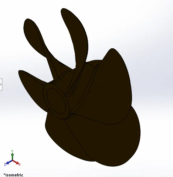
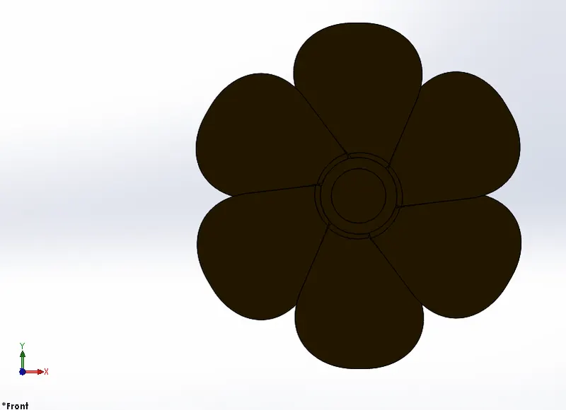
Features used to create propeller:
- Extrude Cut
- Fillet
- Loft
- Revolve
- Circular Patterns
Extrude Cut:
This feature is used to remove materials from the 3D model. It is just opposite of extrude boss because it cuts a sketch profile while extruding. We can cut in both directions and mainly used for creating holes, channels, slots etc.
Fillet:
This feature creates a rounded internal or external face on the part. We can Fillet all the edges of a face, edges, loops etc.
Loft:
The Loft feature allows us to generate complex geometry. It does this by interpolating surfaces between various cross section of the model. These cross sections can be sketches, faces or edges. In the Loft interface the cross sections are considered as Loft profiles
Revolve:
Create a sketch that contains one or more profiles and a Centre line or an edge to use as the axis around which the feature revolves tools.
Circular Patterns
The curve driven pattern tool allows you to create Pattern along a Planar or 3D curve. You can base your pattern on a open curve or on a closed curve such as circle. In the chain part curve driven pattern is used.
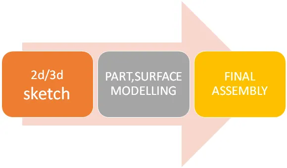
PROCEDURE
- First open a new Solidworks part file.
- Then, select right plane and start sketch.
- Then 2D sketch is created in the right plane and dimensions are given and sketch is fully defined, while sketching we use corner rectangle commands.
- Then we create new plane created and ellipse is drawn in the new plane as per the requirement.
- Then the loft command is used to create loft for the propeller blades.
- The extrude cut is used to remove material from the shaft.
- Then circular pattern is applied to obtain the required number of blades.
- Fillets are applied on the sharper edges for required radius.
- Then finally the part is saved by the name “PROPELLER”.
RADAR
They are electronic navigation instruments that use a rotating antenna to sweep a narrow beam of microwaves around the water surface surrounding the ship to the horizon, detecting targets by microwaves reflected from them, generating a picture of the ship's surroundings on a display screen.
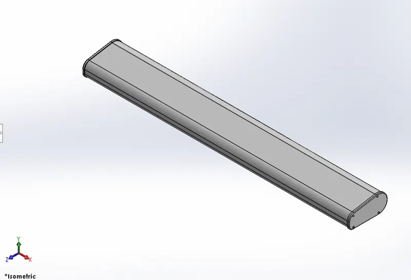
Features used to create radar:
- Boss extrude
- Cut extrude
- Fillet
- Cut extrude
- Split line
- Sketch pattern
HULL
The hull of a yacht is the most notable structural entity of the yacht. To define the hull, it can be said that it is the watertight enclosure of the yacht, which protects the cargo, machinery, and accommodation spaces of the yacht from the weather, flooding, and structural damage.
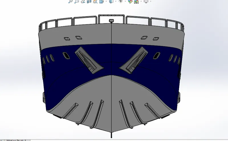
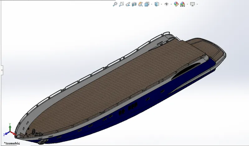
Features used to create hull:
- Surface trim
- Surface extrude
- Surface sweep
- Fillet
- Surface loft
- Dome
- Surface loft
- Sweep surfaces
- Surface extend
- Delete/keep body
Composite curve:
This feature is used to join two curves and makes them a single curve.
eg: combining a projected curve to another curve etc.
Helix/spiral
You can create a helix or spiral curve in a part. The curve can be used as a path or guide curve for a swept feature, or a guide curve for a lofted feature.
Loft surfaces:
Loft surfaces are surfaces generated by multiple 3D curves or existing edges creating a smooth tangency between the selected curves.
Sweep surfaces:
Sweep surfaces are surfaces that are generated that are generated from a section curve positioned along a path.
Fill surface
The fill surface constructs a surface path with number of sides with in a boundary defined by existing model edges, sketches or curves including composite curves.
Surface extend
Used to extend a surface by selecting an edge, multiple edges, or a face. For edges, the surface extends along the plane of the edge.
Surface trim:
Primarily used to cut away material from surface and provides two modes: Standard and Mutual.
Surface knit:
Surface knit is used to knit two free edges/open edges of the surfaces together. Also it reduces the gap between two edges of the surfaces.
Offset surface
The Offset Surface tool creates a new surface body from an existing set of faces. The faces may be solid or surface faces. To create an offset surface:
Extrude Boss/Base:
This feature is used to convert a 2D sketch into 3D model.
Delete/keep body
Used to select bodies to keep or delete using the Delete/Keep Body feature. This is useful in working with multi body parts with multiple configurations.
Mirror
By using mirror faces with a mid plane selected only the chosen faces within the resolve will be mirrored. Mirroring bodies can be used whether in a single or multi body part and allows you to select solid geometry instead of the features and faces in a body. In the fork part the one part is created and other part is mirrored. Then the parts are manually combined.
Sweep:
With the sweep feature we can create a shape by moving a 2D sketch profile along a 2D or 3D sketch path.
Chamfer:
A cut on the edge or corner of something that makes it slope slightly rather being perfectly square
PROCEDURE
- First open a new Solidworks part file.
- Before creating the sketch change the default planes as follows:
- Front Plane – Front plane
- Top Plane –Bottom plane
- Right Plane – Mid plane
- Then two other planes are created and named Back plane and Top plane .
- Necessary sketch image is imported and given proper dimensions and transparency.
- Sketching is strted on bottom plane and then mid plane.
- Projected curves are made made with the help of these sketches to make the body curves of the yacht.
- Then surface bodies are created with the help of these curves and some more 2D&3D sketches.
- The curvy structure of the hull is attained with the help of a number of part surfaces.
- Surface extension, ruled surface, surface trim features are used.
- The made surfaces are combined together with the help of surface knit.
- Then the combined surface body is turned into a solid body.
- Then shell option is given to obtain the desired thickness.
- Then various solid body features like boss/bass extrude, solid sweepetc are used to create the remaining features of the hull.
- Pattern options are given to propagate the features.
- Reference for making the garage door is saved with the help of delete/keep body option.
- Finally the portion is mirrored against the midplane to get the HULL
GARAGE DOOR
A garage door is a large door on a garage that opens either manually or by an electric motor. Garage doors are frequently large enough to accommodate automobiles and other vehicles. Small garage doors may be made in a single panel that tilts up and back across the garage ceiling.
Features used to create garage door:
- Cut extrude
- Shell
- Fillet
- Mirror
Shell:
The shell feature is used to define the thickness of thin and thick shell elements.
FRONT SEAT
Provided in the front area for the passengers, made up of premium upholstery.
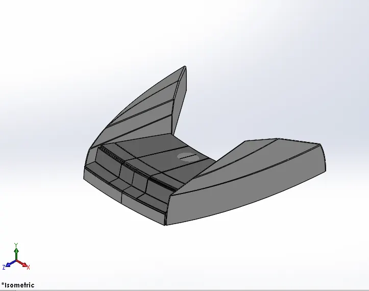
Features used to create front seat:
- Surface trim
- Surface extrude
- Surface sweep
- Fillet
- Surface loft
- Dome
Dome:
This feature is majorly applied to faces. Select one or more planar or non-planar faces. We can apply dome to faces whose centroid lies outside the face. This allows you to apply domes to irregularly shaped contours.
MIDDLE SEAT
Seating area provided in the middle area for the passengers.
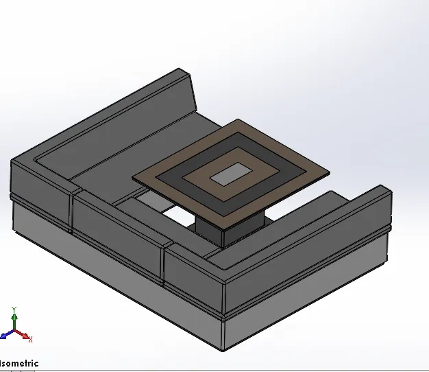
Features used to create engine:
- Body extrude
- Fillet
- Mirror
- Chamfer
- Boss extrude
REAR SEAT
Provided in the rear side of yacht for the passengers.
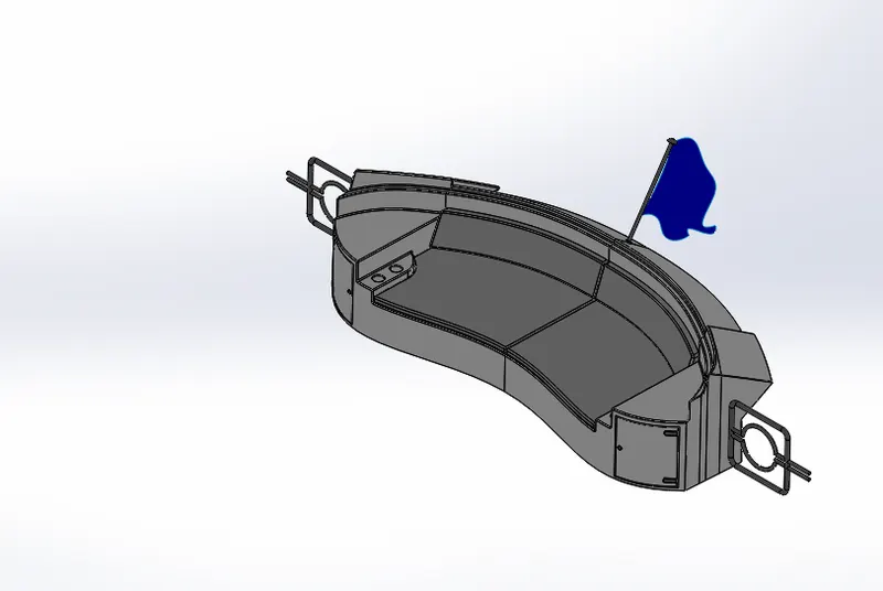
Features used to create rear seat:
- Surface trim
- Surface extrude
- Surface sweep
- Fillet
- Surface loft
- Dome
- Sweep
- Revolve
- Fillet
- Mirror
- Surface knit
- Surface offset
- Ruled surface
SUPERSRUCTURE
On water craft, the superstructure consists of the parts of the ship or a boat, including sailboats, fishing boats, passenger ships, and submarines, that project above her main deck. This does not usually include its masts or any armament turrets.
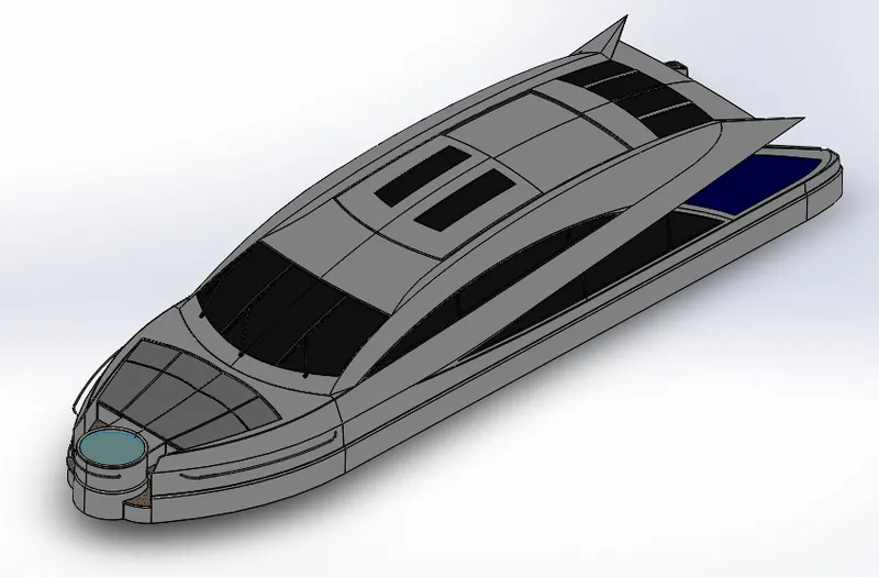
Features used to create superstructure:
- Surface trim
- Surface extrude
- Surface sweep
- Fillet
- Surface loft
- Dome
- Revolve
- Fillet
- Mirror
- Surface knit
- Surface offset
- Ruled surface
- cut extrude
- sweep boss/base
RADAR MAST
The mast of a yacht is a tall spar, or arrangement of spars, erected more or less vertically on the centre-line of a ship or boat. Its purposes include carrying sails, spars, and derricks, and giving necessary height to a navigation light, look-out position, signal yard, control position, radio aerial or signal lamp.[
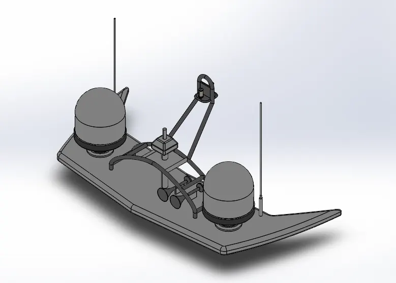
Features used to create radar mast:
- Boss extrude
- Revolve
- Fillet
- Sweep
- Mirror
- Dome
- Shell
ASSEMBLY OF THE YACHT
- Initially the hull part is inserted in the assembly by using insert parts in the option. After that the parts is inserted in the assembly environment and click OK to fix the hull.
- After that other parts of the yacht are inserted into the assembly and given possible mate conditions.
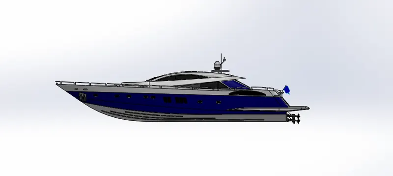
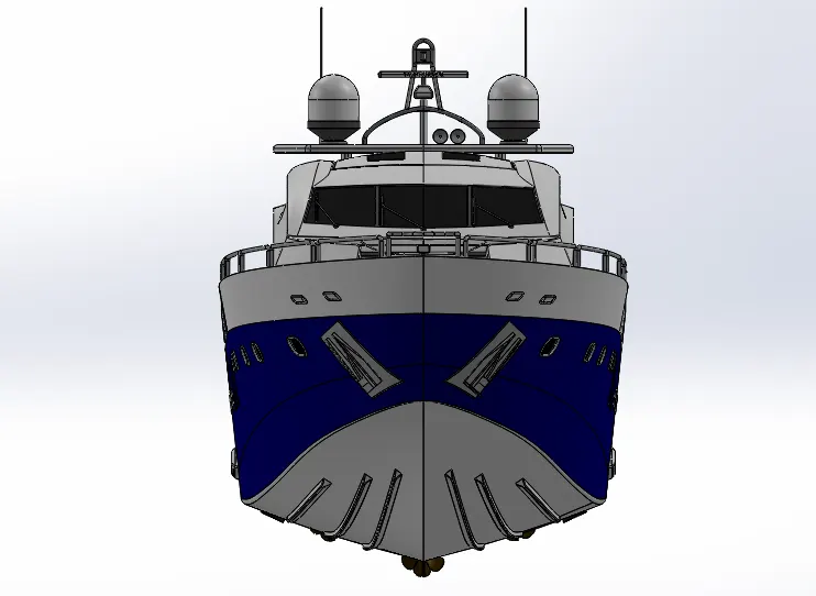
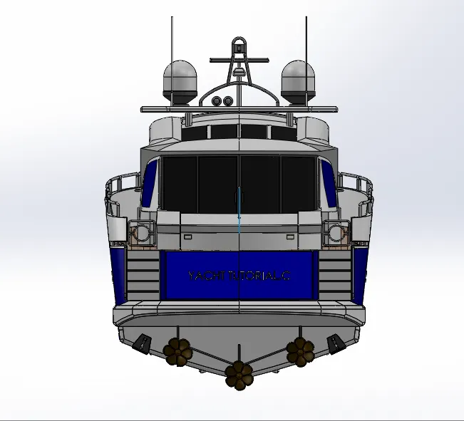
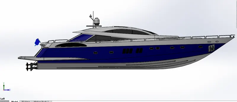
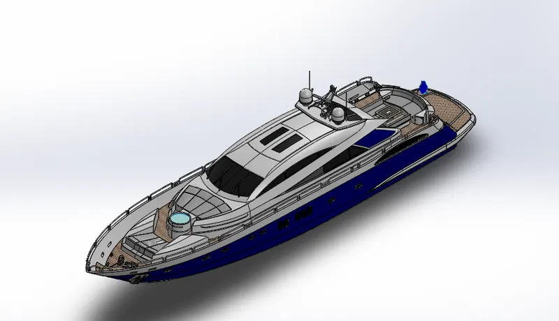
Features used to assemble yacht:
- Inserting parts
- Mates
Mates:
Mates create geometric relationship between the assembly components. As we add mates, we define the allowable directions of linear or rotational motion of the components. We can move a component within its degree of freedom, visualising the assembly behaviour.
RENDERING
- Rendering is a process of creating realistic images of the photorealistic model with the environment.
- Rendering has been done in two ways in Solidworks:
- Photoview 360
- Solidworks Visualize
In the photorealistic model some of the mate conditions and positions are cahged to render realistic models.
Then, the photorealistic model is rendered into realistic images with different views.
Photoview 360:
Photoview 360 is visualization and rendering solution includes with soliworks. Providing a highly interactive environment for viewing designs as well as for creating photorealistic rendering it can be used to showcase our designs as well.
CONCLUSION:
- The parts of the yacht are modelled
- The parts are inserted into assembly environment and the yacht is assembled.