Final Assembly of Yacht
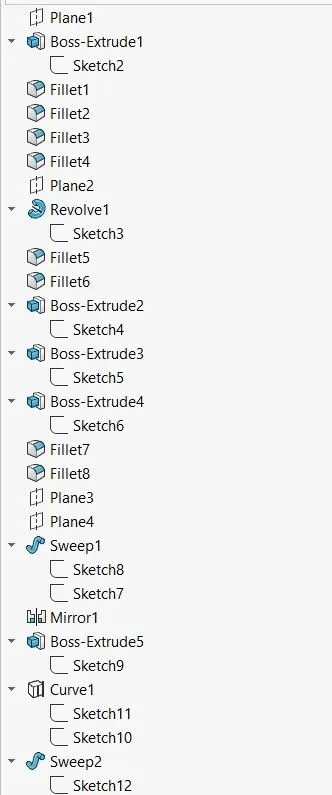
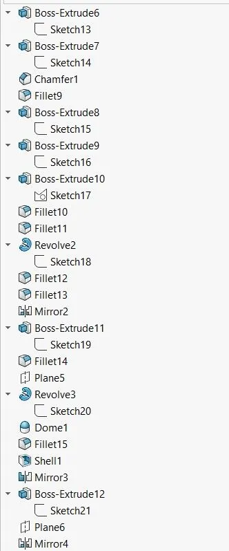
Design, Modelling, Assembly & Photo Realistic Rendering Of Sunseeker Predator Yacht using Solidworks
By: Gaurav Agarwal
INTRODUCTION
Computer-Aided Design (CAD) is widely used in various professional domains like product design, industrial design, bio-medical engineering, research & development, etc. The purpose of this CAD project is to obtain hands-on experience on different aspects of 3D modelling such as solid modeling, surface modeling, assembly creation and photo realistic rendering. The model created in this project is a cosmetic version of the Predator Super-Yacht.
Yacht is a medium sized sailing boat equipped for cruising/racing. Design consideration for yacht is performance, high performance rigs, efficient hulls design which minimizes drag through water and sideways motion.
The whole model is divided into components that are created individually and assembled by defining constraint, resulting in the final desired product.
The components/parts designed and modelled are:
|
1. |
Propeller |
|
2. |
Radar |
|
3. |
Blueprint Setup |
|
4. |
Hull |
|
5. |
Garage Door |
|
6. |
Seats – Front, Middle, Rear |
|
7. |
Superstructure |
|
8. |
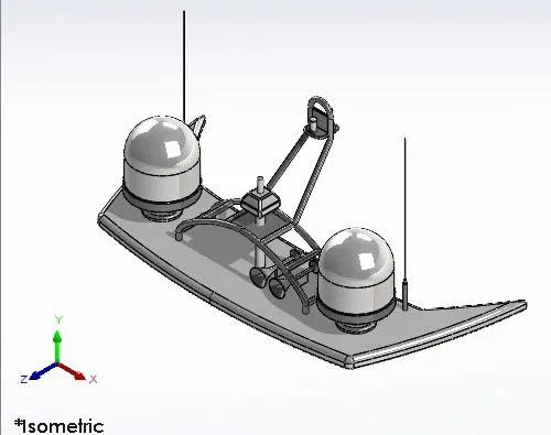
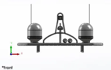
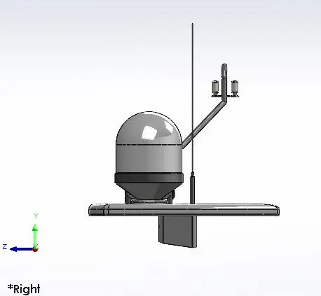
Radar mast |
OBJECTIVE:
- To design and model different parts of the yacht using sketch tools and 3D modelling features of solidworks.
- To assemble all the different parts of yacht.
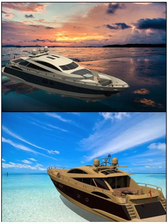
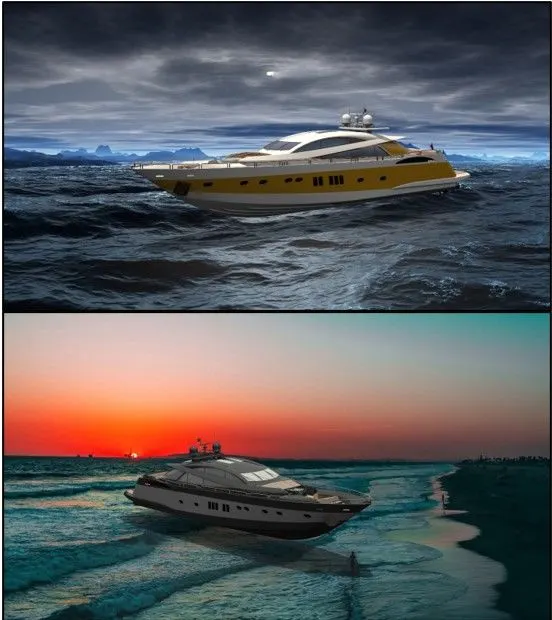
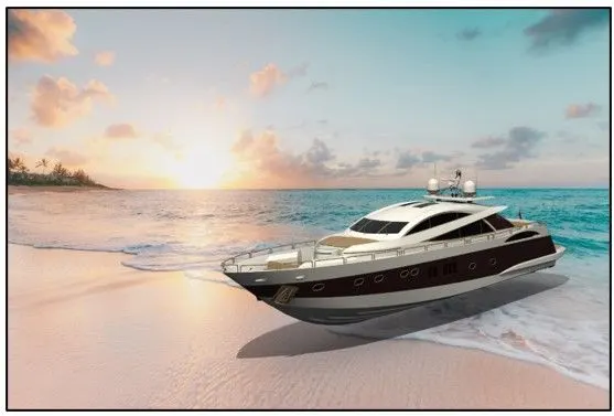
- Rendering images of Yacht in Photoview360 and Solidworks visualization with different environments and views.
Design Approach:
The design procedure can be approached by using two different approaches.
- Bottom-up Approach: The design approach in which the most primary operations are specified first then combined it later to make larger progressive unit.
- Top-down Approach: Top-down assembly modelling is an assembly-centric modelling method where the assembly design is started at the highest level possible, and individual parts and subassemblies are defined within the context of the overall assembly.
Both the approaches have their individual pros and cons, But for our current project we have chosen the bottom-up approach.

3D Modelling Techniques:
- Solid Modelling – Solid Modeling is the computer modeling of 3D solid objects. The objective of Solid Modeling is to ensure that every surface is geometrically correct. This is critical as it lets designers provide cutaways of the design, such as an engine and its components.
- Surface Modelling - Surface Modeling is the method of showing or presenting solid objects. The process requires you to convert between different 3D modeling types, such as converting the 3D object to show procedural surfaces, validate imperfections, and apply smoothness.
- In a CAD environment it is possible to fully produce a model using only surface modeling - but most real-world applications require a combination with solid modeling technique as well.
FEATURES & PROPERTIES USED:
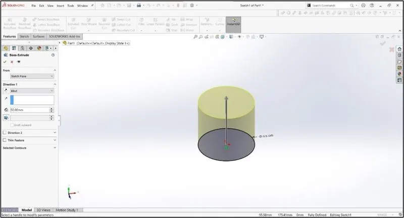
- Extrude Boss:- The most popular feature from SOLIDWORKS is extrude boss. This feature needs a complete 2D sketch to convert 2D sketch into a solid body. When we exit the fully defined sketch we get boss extrude option and a property manager window pop-up. Into the property manager we see from where the feature begins and where it will end that we need to add dimensions to it. It creates a complete solid body of any shape with closed entities. In this feature we can add dimensions to both the direction (direction 1 and direction 2) according to our need. We can use the direction if it is blind, midplane, from the vertex, etc.
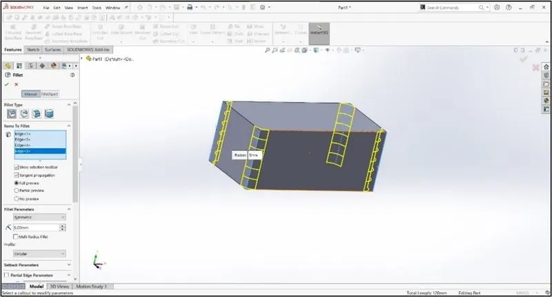
- Fillet:- Solid parts have some sharp edges. To give the roundness to those edges we add fillets. It makes the sharp edges or corners round shape of having different sizes or radius. The material can be added or removed according to conditions whether edges are internal or external. Fillets are used to solid bodies to hide the corners and edges of the part. Various types of fillets are used according to the given condition.
- Extrude cut:- This feature cuts the geometry which we don’t need from the part. This feature also needs a complete 2D sketch, which need to be removed from a solid body. When we draw sketch on the solid part and then we use extrude cut command it removes that part /surface.
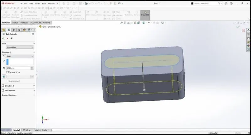
- Surface Extrude:- It is a very powerful tool in SOLIDWORKS. In this tool You can create extruded surfaces from models that include 2D or 3D faces and knit the extruded surfaces to surrounding features.
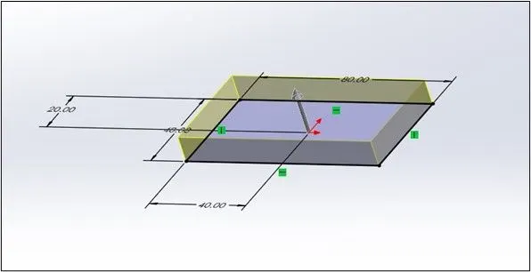
- Surface Loft:- The loft feature is an important tool for (surface) modeling in SolidWorks. The loft feature creates a shape by making transitions between multiple profiles and guide curves. This tool is very valuable for modeling complex surfaces. You can do some cool stuff when you use this feature properly.
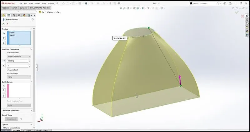
- Surface Sweep:- The sweep feature is an important tool for (surface) modelling in SolidWorks. Sweep is a tool that creates a solid, a cut or a surface feature by moving a profile along a path.
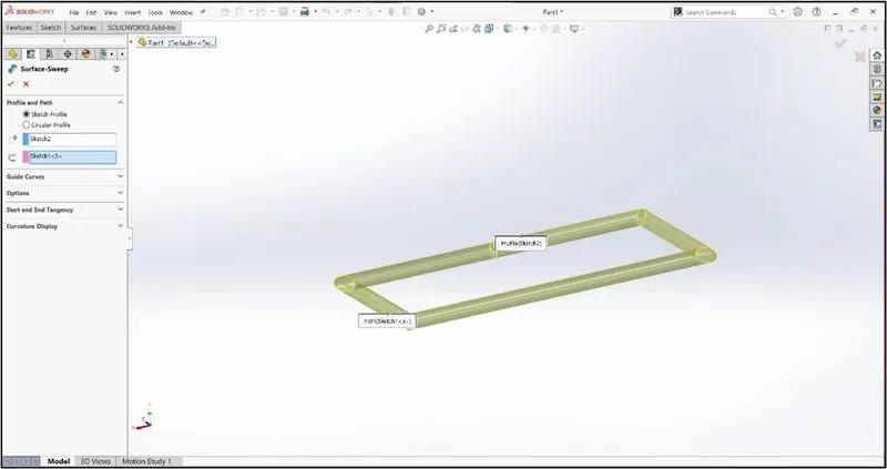
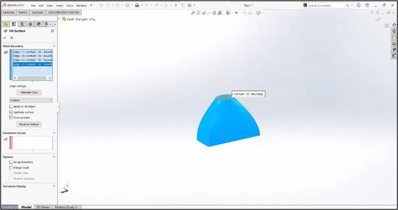
- Surface Fill:- The Filled Surface feature constructs a surface patch with any number of sides, within a boundary defined by existing model edges, sketches, or curves, including composite curves.
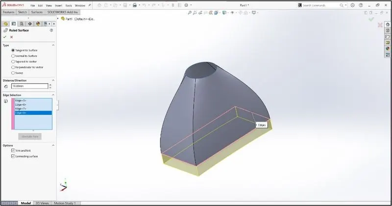
- Ruled Surface:- The Ruled Surface command creates surfaces that extend out in a specified direction from selected edges.
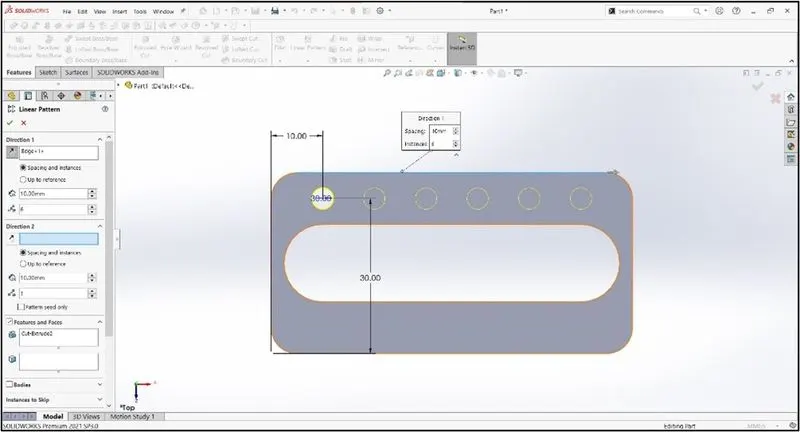
- Linear pattern:- Linear pattern is used to create multiple identical sketches from a single sketch. The spacing, angles and path can be given in this feature to draw or create pattern. This feature is generally spaced uniformly along one or two linear paths.
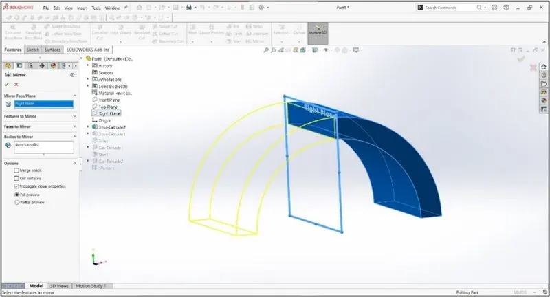
- Mirror:- This feature creates a mirror part for the selected part. It requires a plane or axis to mirror and most importantly the part to be mirrored.
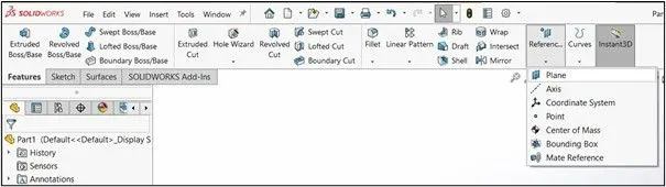
- Reference geometry:- It defines the shape or form of a surface or a solid. This includes features such as planes, axes, co-ordinate system and points. This can be used according to need in a sketch.
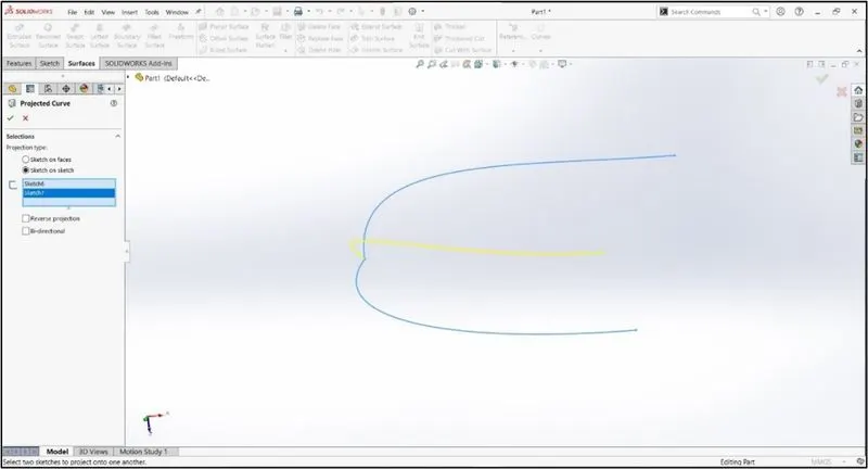
- Projected curve:- This feature helps in projecting a curve from a sketch into a model to create a 3D curve. We can create multiple closed or open contour projected curves from a single sketch. Generally, the curve can be intersection of two extruding surfaces. The curve which is created can be used as a path for the sketch of the part.
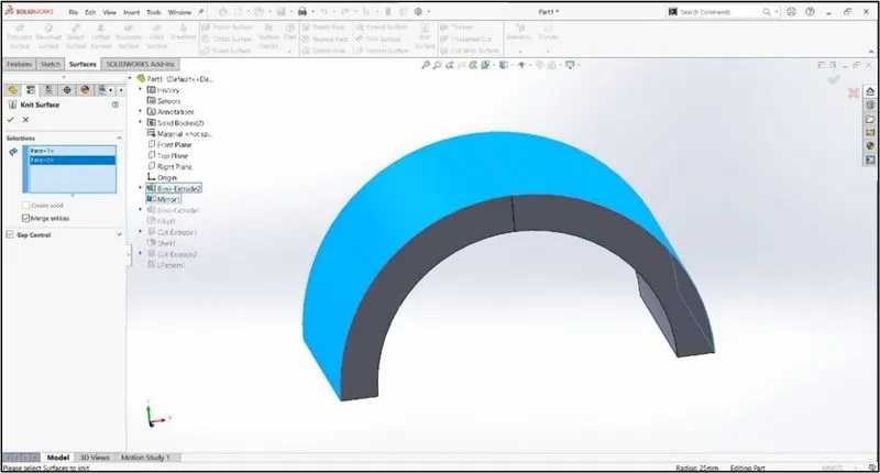
- Surface Knit:- It can be used to knit or to combine two or more faces and surfaces into one. It creates a solid body when the knit surfaces form a closed volume or leave as a surface body.
- Mate:- Mate creates geometric relationship between assembly and component. When we add mates, it defines the allowable direction of linear or rotational motion of component within its degree of freedom, visualizing the assembly’s behaviour.
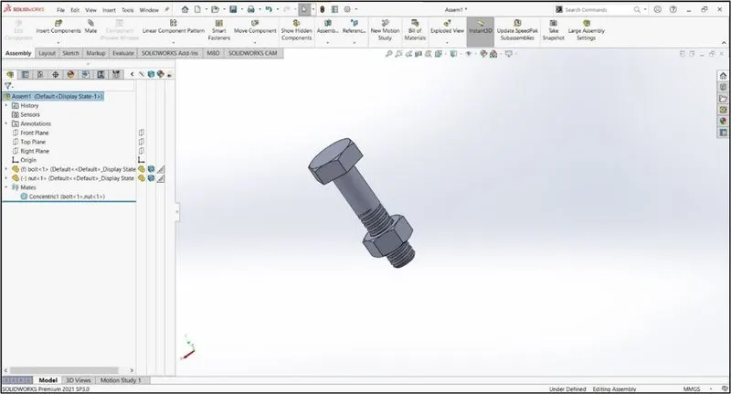
This feature include
- Coincident mate: Coincident mate make two planar faces to become coplanar. This mate can move along one another but cannot be separated.
- Concentric mate: This makes two circular faces to become concentric and can move along the common axis.
- Tangent mate: This feature can be use between a face and plane to make tangent mate.
- Angular mate: This makes angular relation between flat surface and the surface having some angle.
Part Modelling:
- In Part Modelling you can create apart from a conceptual sketch through solid feature-based modeling, as well as build and modify parts through direct and intuitive graphical manipulation.
- Part Modeling shows you how to draft a 2D conceptual layout, create precise geometry using basic geometric entities, and dimension and constrain your geometry. You can learn how to build a 3D parametric part from a 2D sketch by combining basic and advanced features, such as extrusions, sweeps, cuts, holes, slots, and rounds. Finally, the Part Modeling Help provides procedures for modifying part features and resolving failures.
Assembly:
- Assembly modeling is a technology and method used by computer-aided design and product visualization computer software systems to handle multiple files that represent components within a product. The components within an assembly are represented as solid or surface models.
Rendering:
- Photorealistic Rendering lets you adjust various visual aspects of your model to improve its appearance and enhance details for better viewing by your employees and customers. Your model updates as you work, and you can move your model in space to see the effects of your rendering from different angles.
Features used in modelling of components/parts for Yacht
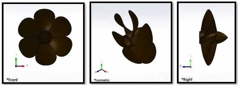
Propeller:
A propeller is a device with a rotating hub and radiating blades that are set at a pitch to form a helical spiral, that, when rotated, exerts linear thrust upon a working fluid, such as water or air. Propellers are used to pump fluid through a pipe or duct, or to create thrust to propel a boat through water. The blades are specially shaped so that their rotational motion through the fluid causes a pressure difference between the two surfaces of the blade by Bernoulli's principle which exerts force on the fluid. Most marine propellers are screw propellers with helical blades rotating on a propeller shaft with an approximately horizontal axis. Features used to create the Propeller are:
- Revolve
- Loft
- Fillet
- Cut Extrude
- Circular pattern
Radar:
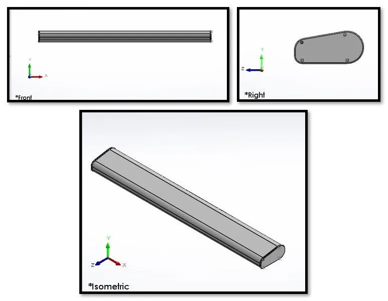
Radars used to detect other ships and land obstacles, to provide bearing and distance for collision avoidance and navigation at sea. They are electronic navigation instruments that use a rotating antenna to sweep a narrow beam of microwaves around the water surface surrounding the ship to the horizon, detecting targets by microwaves reflected from them, generating a picture of the ship's surroundings on a display screen. Radar is a vital navigation component for safety at sea and near the shore. Features used to create the Radar are:
- Sketch
- Boss extrude
- Mirror
- Sketch driven pattern
- Split line
Blueprints setup:
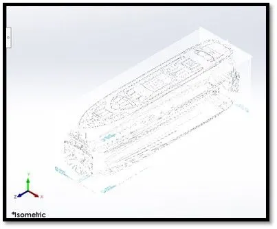
A blueprint is a guide for making something — it's a design or pattern that can be followed.
Hull:
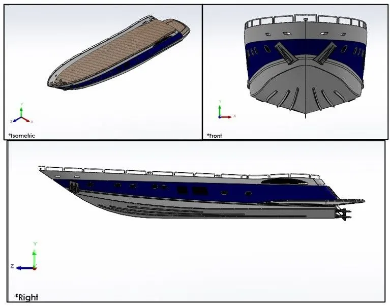
The hull of a ship is the most notable structural entity of the ship. To define the hull, it can be said that it is the watertight enclosure of the ship, which protects the cargo, machinery, and accommodation spaces of the ship from the weather, flooding, and structural damage. Features used to create the hull are:
- Projected curve
- Surface loft
- Surface trim
- Surface extrude
- Shell
- Chamfer
- Sweep
- Dome
- Linear pattern
- Combine
- Move/Copy/Delete Bodies
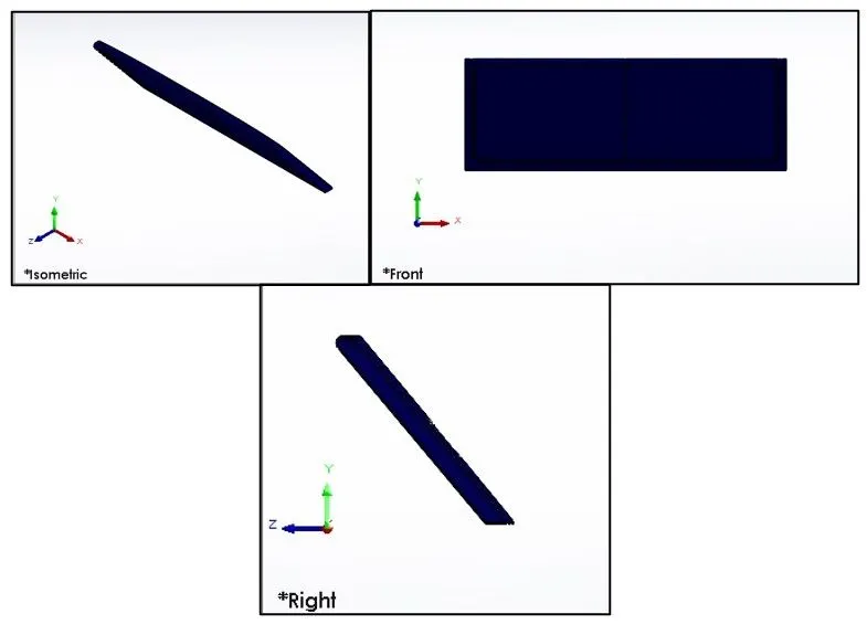
Garage Door:
A garage door is a large door on a garage that opens either manually or by an electric motor. Garage doors are frequently large enough to accommodate automobiles and other vehicles. Small garage doors may be made in a single panel that tilts up and back across the garage ceiling.
Superstructure:
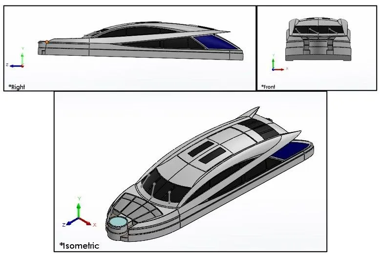
A superstructure is an extended construction of any building or platform that rises above the rest of the building or platform in a distinct manner. The word comes from a combination of two Latin words, the Latin prefix ‘super’ means in addition or above, whereas the stem word ‘structure’ means to build or to heap up. Thus, superstructure means to add a construction to an already existing structure. In ships this is the name given to the part of the ship that emerges from the deck. Features used to create the superstructure are:
- Surface sweep
- Surface knit
- Ruled surface
- Surface fill
- Surface extend
- Projected curve
- Mirror
- Surface extrude
Front seat:
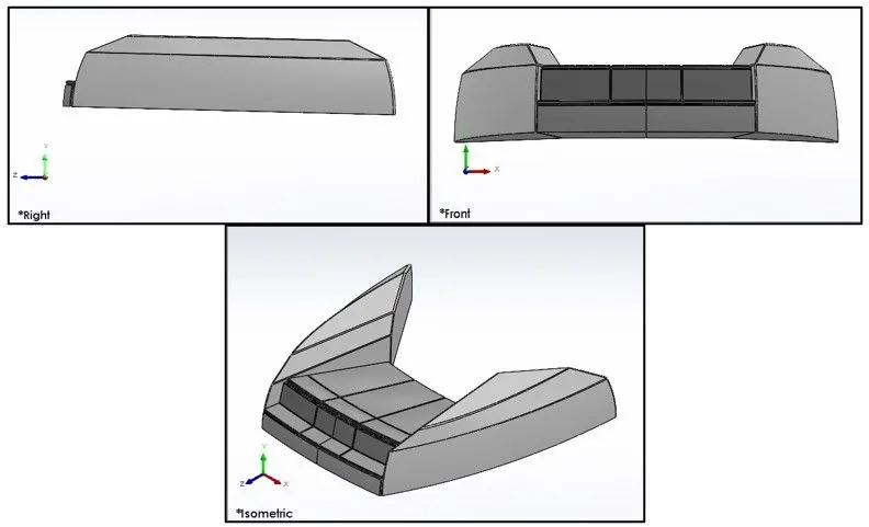
Features used to create the front seat are:
- Surface sweep
- Surface trim
- Surface extrude
- Surface fill
- Surface loft
- Surface knit
- Revolve
- Chamfer
- Fillet
- Dome
- Mirror
Middle seat:
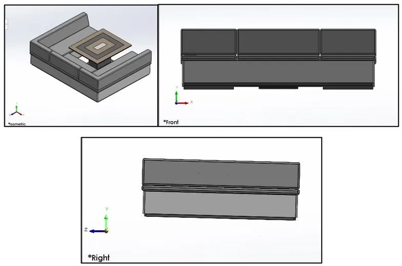
Features used to create the middle seat are:
- Boss extrude
- Chamfer
- Reference Planes
- Fillet
- Mirror
- Cut extrude
Rear seat:
Features used to create the rear seat are:
- Surface sweep
- Surface offset
- Ruled surface
- Surface trim
- Surface offset
- Surface knit
- Surface extend
- Surface extrude
- Boss extrude
- Cut extrude
- Revolve
- Sweep
- Mirror
- Fillet
- Surface fill
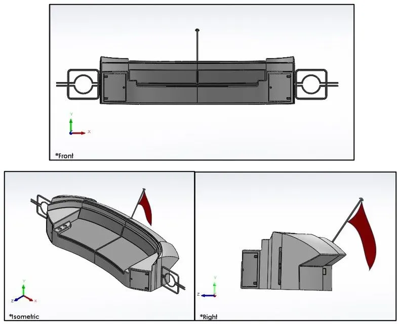
Radar mast:
It is upright pole, erected vertically on center of a ship. Its purpose include carrying sails, spars, derricks, and giving necessary height to a navigation light, signal yard, control position etc. Features used to create the radar mast are:
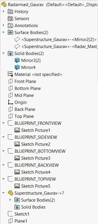
- Sketch
- Extrude boss/base
- Extrude cut
- Knit surface
- Mirror
- Fillet
- Chamfer
- Dome
- Extend surface
- Combine
- Projected curve
- Appearance
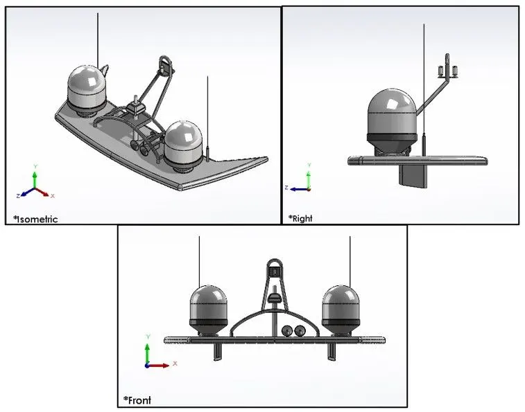
Assembly
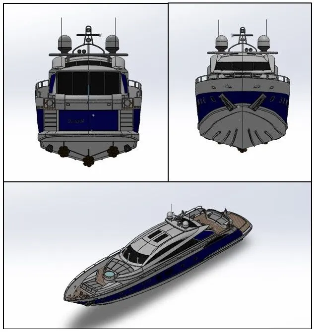
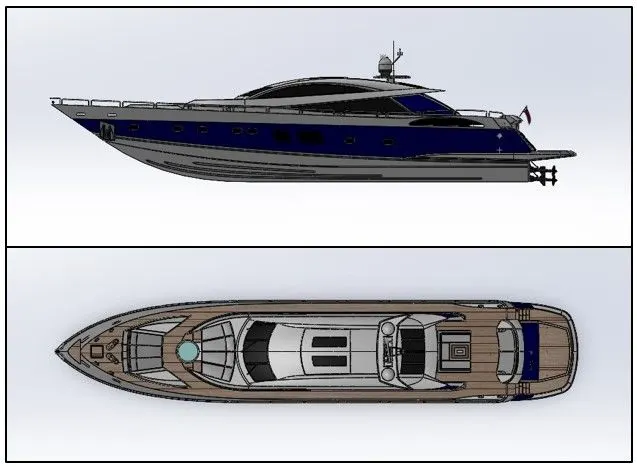
- Assembly modelling is a technology and method used by computer-aided designand product visualization computer software systems to handle multiple files that represent components within a product. The components within an assembly are represented as solid or surface models.
- Firstly, import all modelled part document file into SOLIDWORKS assembly window one at a time. Then with the use of mate assign proper relationships between the parts as they get imported. Also assign proper positions to the parts relative to each other.
- Lastly, modify any part document according to the need of the assembly.
- Mates use are: concentric mate, coincident mate etc.
Rendering
- Photorealistic Rendering lets you adjust various visual aspects of your model to improve its appearance and enhance details for better viewing by your employees and customers. Your model updates as you work, and you can move your model in space to see the effects of your rendering from different angles.
- In SOLIDWORKS rendering can done using solidworks visualize, under new project import the model to be modelled. Now in rendering we can change colour of chopper parts, background images, brightness, rotation and various setting of chopper.
Conclusion:
- All the parts of the yacht are modelled and assembled successfully using solidworks.
- Superstructure and rear seat are the most complex parts of the whole model.
- Gained Hand-on experience on surface-modelling, 3D sketching etc.