Radar Mast & Final Assembly of Yacht
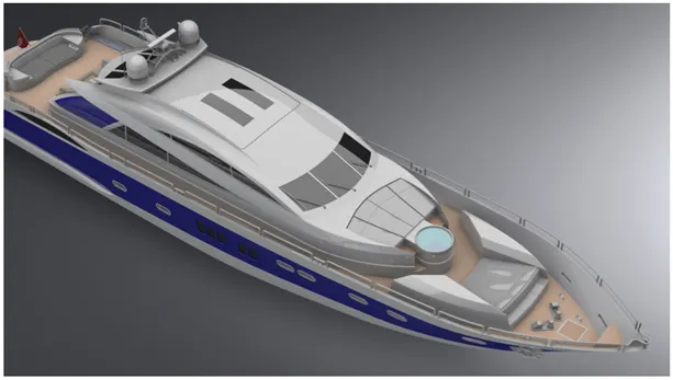
Modeling and Rendering of Sunseeker Predator Yacht using Solidworks
OBJECTIVE :-
- Creating surface models of different parts of an Yacht using Solidworks part modelling interface
- To assemble the different parts of an Yacht that are modelled using solid works assembling interface,
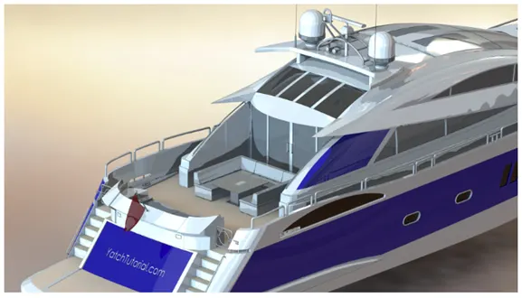
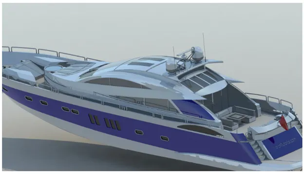
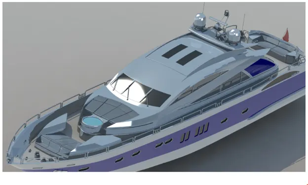
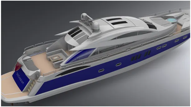
- Rendered the final assembly to get photorealistic model using photoview 360 & solidworks visualize.
- Part modelling :-
- Part modelling is the process of creating a conceptual 3d model using sketch of the concept.
- The sketches form the base for the parts that are required to be modelled.
- These sketches are then converted to 3d models using different features available.
- At the end you will get the parametric model of the required part using the part modelling.
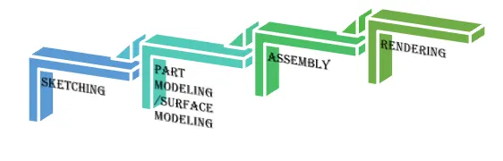
Different features that are used to create the parts :-
- Sketch: sketching is the 2 dimensional representation of the required model with respect to the sketching plane. A sketch must be fully define using relations and dimensions
- Sketch entities; - In solid works there are different options available to create sketch by using sketching entities such as line, arc, circles, spline, rectangle etc.
- Sketch editing :- There are different options to edit the required sketches to get the required design/concept, some are explained below,
- Trim: Remove/trim the unwanted sketch/entities of the selected sketch or the intersecting edge of the sketch.
- Extend: extends the lines /entities up to the selected length or to the selected point,
- Mirror: produces the mirror entities of the selected sketch over the selected mirror line/axis,
- Offset: This is used to get the copy of the selected sketch over offset distance and also of n numbers at the either sides of the sketch.
- Extrude Boss/Bass: Extrude is the process of stretching flat 2D sketch vertically in either directions to create a 3D shape/model.
- Fillet: fillet creates a rounded internal or external faces, selected set of faces, selected edges, or edge loops.
- Lofted Boss/Bass: Loft creates a feature by making transition between profiles by interpolating surfaces between various cross-sections of a model. This cross-section can be sketches, faces, or edges. The corrections are considered as “loft profiles”.
- Dome: Dome is half spherical face that can be applied on to a selected one or more planar or nonplanar faces. Apply domes to faces whose centroid lies outside the face. This allows applying domes to irregularly shaped contours.
- Revolve Bass : to create revolve feature create a sketch that contains one or more profiles and a centreline, line, edge, to use as the axis around which the sketched feature revolves.
- Revolve cut: This feature works opposite to the revolve bass. The revolve cut removes material according to the sketch which is created and revolved around the axis i.e. centreline, line or edge
- Extrude Cut: feature helps remove material from the 3D model. It is just opposite to the extrude bass feature, because it cuts the model with respect to this profile created on either sides. Mainly used to create holes, slots, channels etc.
- Shell: the shell feature create a hollow model of the selected 3d model by defining the wall thickness.
- Combine : the function allows you to add two bodies together and keep the area which is common in both.to use the feature select the common bottom and the under bodies to combine select the two bodies.
- Split: This feature allows splitting the model into different bodies or even remove the unwanted area by using consume bodies of the selected model and keep the required parts of the model. This feature works opposite to the combine feature.
- Dynamic Mirror: This tool allows the user to mirror a sketch about a line while the user is creating their sketch. Depending on design intent this tool can save an immense amount of time. As you create sketch they are mirrored over a preselected line,
- Appearance: The appearance defines the visual properties if the model like colour, texture, surface reflection etc. of the selected body or face. Even by assigning the material to the part the appearance associated with it is applied.
- Chamfer: The chamfer tool creates a bevelled feature on selected edges, faces, or a vertex. This creates a slope like feature on the corners or edges rather than giving a squared sharp edge.
- Patterns: A pattern is an arrangement of sketch or shapes, especially a design in which the same shape is repeated at regular intervals over a surface/face with a specified distance between them.
- Circular pattern are used to create a feature of required instance in a circular orientation.
- Linear pattern are used to create a feature of required instance in a linear orientation.
- Projected curve: creates a 3D curve that represents the intersection of two sketch curves created on two intersecting planes.
- Composite curve: creates composite curves by combining curves, sketch geometry, and model edges into a single curve.
- Sweep bass: SWEEP is the one feature in Solid works that helps sweep a closed profile along a closed or open path. A closed profile and a sweep path are requirements of the sweep feature.
- Helix/spiral: creates a helix or spiral kind of a feature based on the sketch created
- Sketch blocks: Blocks are independent, non-solving sketches that can be used in a variety of ways inside of SOLIDWORKS. The most common would be to copy a sketch and then use that sketch somewhere else in your design. By creating a block, all the entities in the block become frozen.
- Surface features :-
- Surface modelling create the exterior surface of the required model by curves that are sketched, the surface model has a zero thickness.
- Types of features in surface model used:-
- Lofted surface: surfaces created by multiple curves or existing edges of the present part, which creates the smooth tangency between selected curves/edges.
- Swept surface: swept surfaces are generated similar to the swept boss; surfaces are formed by selecting a path and a curve that sweep along the path.
- Filled surface: this creates a surface patch over a selected any number of sides within a boundary defined by sketch, curves or edges.
- Ruled surface: Ruled surface is formed by creating swept surface using selected edges.
- Extend surface: extended surface extends the surface which is already created, the surface can be extended a same surface or extend it tangentially with respect to the present surface.
- Knit surface: is used to knit the fee or open edges pf two different surfaces together which reduces the gap between the two edges of the surface.
- Surface Trim: Surface trim is used to trim or remove surface which overlaps or intersects the other surface or plane or body.
Different parts modelled using the above features
- PROPELLER
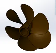
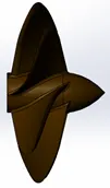
- A PROPELLER is a turbo mechanism which transmits power by converting rotational motion into thrust .
- By pushing water I reverse direction to the motion of Yacht with the help of the blades.
- Features used to create
- Sketch
- Revolve
- Extrude cut
- Fillet
- Loft
- Circular Pattern
- Appearance
- RADAR
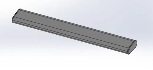
- RADARS are used to transmit signals 0r radio waves which helps to detect other ships and obstacles
- Features used to create
- Sketch
- Extrude
- Mirror
- Extrude cut
- Fillet
- Patterns
- Appearance
- HULL:
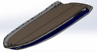
- It is a water tight body which forms the main support to a Boat or ship to float
- The top surface of hull is the deck
- The hull holds all the other parts together
- Features used to create
- Sketch
- Projected curve
- Swept surface
- Loft surface
- Extrude surface
- Extend surface
- Surface Knit
- Extrude
- Sweep
- Mirror
- Extrude cut
- Pattern
- Shell
- Filled surface
- Trim surface
- Chamfer
- Dome
- Helix/spiral
- Combine
- Appearance
- GARAGE DOOR:
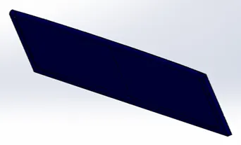
- It is the door which closes the garage part of hull
- Features used to create
- Insert
- Shell
- Split
- Extrude
- Fillet
- Text
- Appearance
- FRONT / MIDDLE / REAR SEATING :
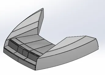
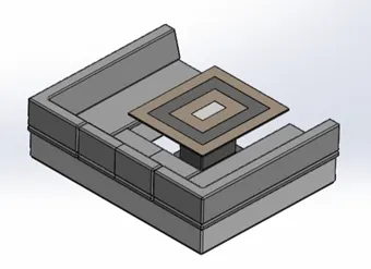
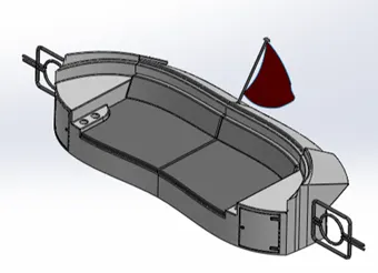
- Seating arrangement is quit artistic on a yacht
- Front/Middle/Rear seats are places to hang out or rest on a yacht
- These are placed in front, middle, rear part of the hull respectively
- Features used to create
- Sketch
- Projected curve
- Ruled surface
- Swept surface
- Loft surface
- Extended surface
- Surface knit
- Extrude
- Mirror
- Cut extrude
- Fillet
- Chamfer
- Pattern
- Appearance
- SUPERSTRUCTURE:
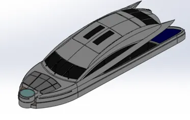
- It means building the structure on already built structure
- This is built on the deck surface of the Yacht
- It consists of rooms/kitchen etc.
- It basically gives an indoor experience on a yacht
- Features used to create
- Sketch
- Projected curve
- Ruled surface
- Swept surface
- Loft surface
- Extended surface
- Filled surface
- Delete surface
- Surface knit
- Extrude
- Mirror
- Cut extrude
- Fillet
- Chamfer
- Pattern
- Appearance
- RADAR MAST :
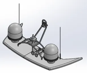
- Features used to create
- Sketch
- Extrude boss
- Revolve
- Sweep
- Extrude cut
- Fillet
- Appearance
Assembling the Predator Yacht :
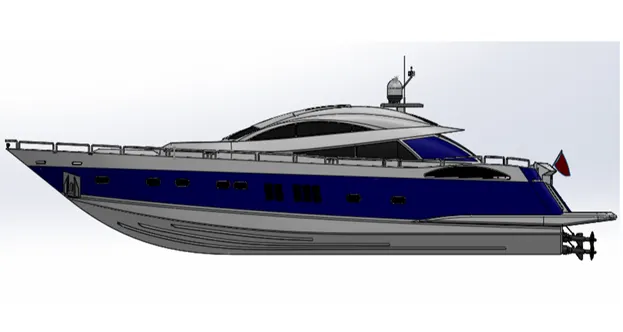
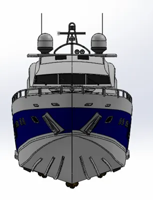
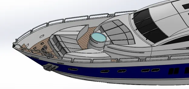
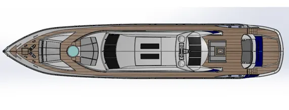
- The assembly interface uses the defined mates of the inserted bodies to position them in the main assembly and hold them together
- Mates create relations between the defined components in the assembly, some of the mates are allowable linear or rotational motion, coincident mate b/w the components, distance b/w the components etc.
- All the parts are inserted one by one and assembled by giving mates
- Hull is the first part inserted as it forms the basis for other parts to get assembled
- As the deck surface is the reference for majority of parts , the parts get assembled automatically when inserted in assembly environment
- Radar, Propeller & garage door are to be assembled manually by giving mate conditions
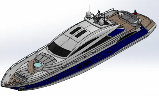
Rendering the Predator Yacht:
- Rendering is the process of creating photorealistic images of the 3d model
- Rendering of the Yacht is done by using features available in the phot view 360 and solid works visualize.
- In rendering interface first verified the different appearances of all the components.
- Then applied some decals on to the deck, stairs etc.
- The inserted some scene or backgrounds where the yacht has to be place to have realistic image.
- Then inserted the camera to adjust the view on the chopper
- Then played along with some of the cool features available like inserting lights, perspective, brightness, gamma feature, adding different scene, appearance etc.
- Photoveiw 360
- Solidworks visualize :
- Conclusion :
- Parts of the Yacht are modelled using solidwork part modeling interface.
- The parts are then inserted in assembly interface and assembled.
- The realistic rendering is done using photoveiw 360 & solidworks visualize.