Photo Realistic Rendering
- OBJECTIVE :-
- Creating models of different parts of an American chopper using Solidworks part modelling interface
- To assemble the different parts of an American chopper that are modelled using solid works assembling interface,
- Rendered the final assembly to get photorealistic model using photoview 360 & solidworks visualize.
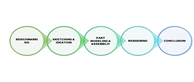
- Benchmarking :
- Benchmarking is the process of comparing & evaluating the of the products or process which is already available,
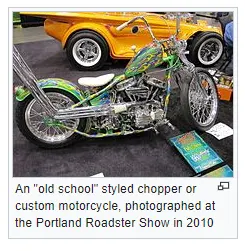
- A chopper is a type of custom motorcycle which emerged in California in the late 1950s. The chopper is perhaps the most extreme of all custom styles, often using radically modified steering angles and lengthened forks for a stretched-out appearance.
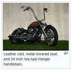
- Some of the characteristic features of choppers are long front ends with extended forks often coupled with an increased rake angle, hardtail frames (frames without rear suspension), very tall "ape hanger" or very short "drag" handlebars, lengthened or stretched frames, and larger than stock front wheels.
- The "sissy bar", a set of tubes that connect the rear fender with the frame, and which are often extended several feet high, is a signature feature on many choppers.
- Choppers mostly have a Retro & some kind of a Pop look
- Some or the referred designs to get a clear picture of a chopper
- Sketching & Ideation :
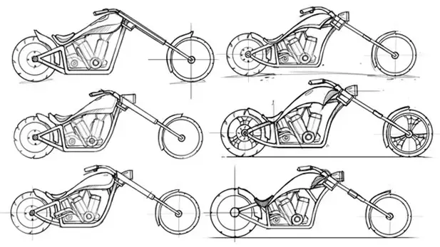
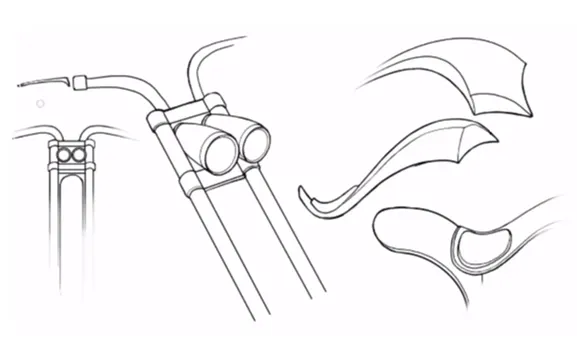
- By considering some designs of the previously available chopper , need to create a rough sketch by considering some trade mark features like long front ends with extended forks often coupled with an increased rake angle, hardtail frames (frames without rear suspension), very tall "ape hanger" or very short "drag" handlebars, lengthened or stretched frames, and larger than stock front wheels.
- Sketch may not be perfect at the first but need to be refined in later stages.
- one can also consider some of the artistic feature/styles/patterns seen in and around us to utilise those in chopper detailing.
- Part modelling :-
- Part modelling is the process of creating a conceptual 3d model using sketch of the concept.
- The sketches form the base for the parts that are required to be modelled.
- These sketches are then converted to 3d models using different features available.
- At the end you will get the parametric model of the required part using the part modelling.
- Different features that are used to create the parts of an American chopper :-
- Sketch: sketching is the 2 dimensional representation of the required model with respect to the sketching plane. A sketch must be fully define using relations and dimensions
- Sketch entities; - In solid works there are different options available to create sketch by using sketching entities such as line, arc, circles, spline, rectangle etc.
- Sketch editing :- There are different options to edit the required sketches to get the required design/concept, some are explained below,
- Trim: Remove/trim the unwanted sketch/entities of the selected sketch or the intersecting edge of the sketch.
- Extend: extends the lines /entities upto the selected length or to the selected point,
- Mirror: produces the mirror entities of the selected sketch over the selected mirror line/axis,
- Offset: This is used to get the copy of the selected sketch over offset distance and also of n numbers at the either sides of the sketch.
- Extrude Boss/Bass: Extrude is the process of stretching flat 2D sketch vertically in either directions to create a 3D shape/model.
- Fillet: fillet creates a rounded internal or external faces, selected set of faces, selected edges, or edge loops.
- Lofted Boss/Bass: Loft creates a feature by making transition between profiles by interpolating surfaces between various cross-sections of a model. This cross-section can be sketches, faces, or edges. The corrections are considered as “loft profiles”.
- Dome: Dome is half spherical face that can be applied on to a selected one or more planar or nonplanar faces. Apply domes to faces whose centroid lies outside the face. This allows applying domes to irregularly shaped contours.
- Revolve Bass : to create revolve feature create a sketch that contains one or more profiles and a centreline, line, edge, to use as the axis around which the sketched feature revolves.
- Revolve cut: This feature works opposite to the revolve bass. The revolve cut removes material according to the sketch which is created and revolved around the axis i.e. centreline, line or edge
- Extrude Cut: feature helps remove material from the 3D model. It is just opposite to the extrude bass feature, because it cuts the model with respect to this profile created on either sides. Mainly used to create holes, slots, channels etc.
- Shell: the shell feature create a hollow model of the selected 3d model by defining the wall thickness.
- Combine : the function allows you to add two bodies together and keep the area which is common in both.to use the feature select the common bottom and the under bodies to combine select the two bodies.
- Split: This feature allows splitting the model into different bodies or even remove the unwanted area by using consume bodies of the selected model and keep the required parts of the model. This feature works opposite to the combine feature.
- Dynamic Mirror: This tool allows the user to mirror a sketch about a line while the user is creating their sketch. Depending on design intent this tool can save an immense amount of time. As you create sketch they are mirrored over a preselected line,
- Appearance: The appearance defines the visual properties if the model like colour, texture, surface reflection etc. of the selected body or face. Even by assigning the material to the part the appearance associated with it is applied.
- Chamfer: The chamfer tool creates a bevelled feature on selected edges, faces, or a vertex. This creates a slope like feature on the corners or edges rather than giving a squared sharp edge.
- Patterns: A pattern is an arrangement of sketch or shapes, especially a design in which the same shape is repeated at regular intervals over a surface/face with a specified distance between them.
- Circular pattern are used to create a feature of required instance in a circular orientation.
- Linear pattern are used to create a feature of required instance in a linear orientation.
- Projected curve: creates a 3D curve that represents the intersection of two sketch curves created on two intersecting planes.
- Composite curve: creates composite curves by combining curves, sketch geometry, and model edges into a single curve.
- Sweep bass: SWEEP is the one feature in Solid works that helps sweep a closed profile along a closed or open path. A closed profile and a sweep path are requirements of the sweep feature.
- Sketch blocks: Blocks are independent, non-solving sketches that can be used in a variety of ways inside of SOLIDWORKS. The most common would be to copy a sketch and then use that sketch somewhere else in your design. By creating a block, all the entities in the block become frozen.
- Surface features :-
- Surface modelling create the exterior surface of the required model by curves that are sketched, the surface model has a zero thickness.
- Types of features in surface model used:-
- Lofted surface: surfaces created by multiple curves or existing edges of the present part, which creates the smooth tangency between selected curves/edges.
- Swept surface: swept surfaces are generated similar to the swept boss; surfaces are formed by selecting a path and a curve that sweep along the path.
- Filled surface: this creates a surface patch over a selected any number of sides within a boundary defined by sketch, curves or edges.
- Extend surface: extended surface extends the surface which is already created, the surface can be extended a same surface or extend it tangentially with respect to the present surface.
- Knit surface: is used to knit the fee or open edges pf two different surfaces together which reduces the gap between the two edges of the surface.
- Different parts modelled using the above features
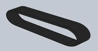
- TRANSMISSION BELT
- A belt drive is a transmission system that uses a flexible strip to transfer power from the two or more rotating pulleys
- The belt drive is used for different purposes in the engine to run the cooling system, to run the timing valves, in cars to run air conditioning, some cases even to drive the wheels directly.
- Features used to create
- Sketch
- Offset
- Extrude
- Fillet
- Appearance
- Chain
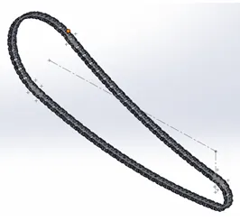
- Chain drive is a way of transmitting mechanical power from one place to another. It is often used to convey power to the wheels of a vehicle, particularly bicycles and motorcycles. It is also used in a wide variety of machines besides vehicles.
- The chain connects the two sprockets, one on the rear wheel the other on the engine.
- Features used to create
- Sketch
- Trim
- Fillet
- Sketch blocks
- Extrude
- Patterns
- Appearance
- Kickstand:
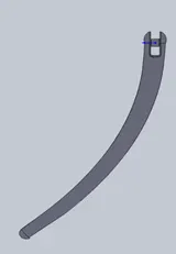
- It can be defined simply as a metal rod attached to a bicycle or motorcycle, lying horizontally when not in use, that may be kicked into a vertical position to support the vehicle when it is stationary.
- Features used to create
- Sketch
- Loft boss
- Dome
- Extrude boss
- Extrude cut
- Fillet
- Split
- Appearance
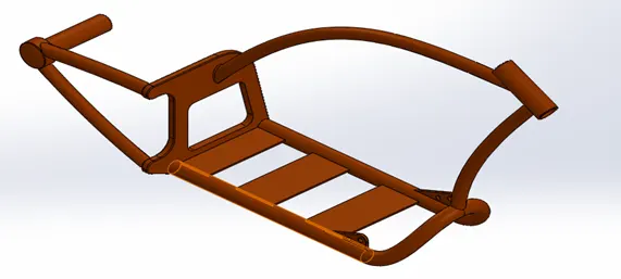
- Chassis :
- Much like a human spine and the supporting skeleton, a motorcycle chassis holds everything together - from the engine, suspension, wheels, fuel tank, handlebars, seat, air box etc. Every bike's handling depends on various factors such as suspension tuning, weight, tyres and most importantly the strength and rigidity of the frame.
- Features used to create
- Sketch
- Offset
- Projected curve
- Trim
- Sweep
- Split
- Revolve
- Extrude cut
- Fillet
- Combine
- Appearance
- Front and Rear Fenders :
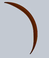
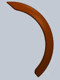
- Fender is the American English term for the part of an automobile, motorcycle or other vehicle body that frames a wheel well (the fender underside). Its primary purpose is to prevent sand, mud, rocks, liquids, and other road spray from being thrown into the air by the rotating tire.
- Features used to create
- Sketch
- Offset
- Trim
- Revolve
- Dynamic mirror
- Split
- Appearance
- Front fender
- Rear Fender
- Front & Rear Wheels :
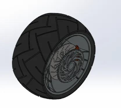
- Wheel is a circular block of a hard and durable material at whose centre has been bored a hole through which is placed an axle bearing about which the wheel rotates when torque is applied to the wheel about its axis.
- In this model the wheel is model in such a way that the rim, tyre, brake disc, sprocket (in rear wheel), brake calliper all modelled as a single instead of modelling each of them separately and assembling them.
- Features used to create
- Sketch
- Revolve
- Trim
- Fillet
- Extrude boss
- Revolve cut
- Linear pattern
- Chamfer
- Circular pattern
- Extrude cut
- Appearance
- Front wheel
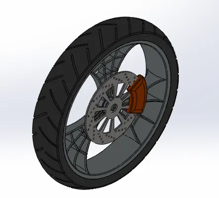
- Rear wheel
- Oil Tank :
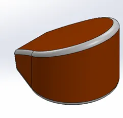
- It stores the oil that is used to lubricate the reciprocating parts of the engine thus the oil helps in smooth movement of the reciprocating and rotating parts of the engine.
- Features used to create
- Sketch
- Extrude boss
- Combine
- Fillet
- Shell
- Appearance
- Pedal :
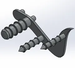
- Pedal is a support structure where the rider places his foot while riding the bike & it is attached to chassis.
- Features used to create
- Sketch
- Extrude
- Fillet
- Linear pattern
- Dome
- Chamfer
- Appearance
- Front Fork :
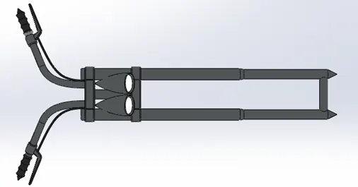
- Front fork serves as rigidity component just like a frame. ... The front fork prevents excessive weight on the front wheel during drastic sudden applications the break, softens bumping when driving on rough road surfaces. The front fork maintains proper damping through traction with the road surface.
- The fork holds the front wheel through the axle and helps steering through the curves while riding.
- Features used to create
- Sketch
- Extrude
- Trim
- Revolve
- Split
- Insert plane
- Move/copy body
- Dome
- Mirror
- Combine
- Projected curve
- Sweep
- Appearance
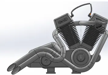
- Engine :
- Engine provides the energy that is required to drive the wheels, it utilizes the fuel to produce heat energy and convert it into mechanical energy to drive the wheels.
- The burning of fuel in the engine cylinder imposes a reciprocating motion in the piston which is converted to rotating motion by the crankshaft; this motion is transmitted to the rear wheel by means of gear drives and chain & sprocket arrangement.
- Features used to create
- Sketch
- Trim
- Revolve
- Extrude boss
- Extrude cut
- Offset
- Dome
- Fillet
- Projected curve
- Composite curve
- Sweep
- Mirror
- Circular pattern
- Split
- Gas Tank :
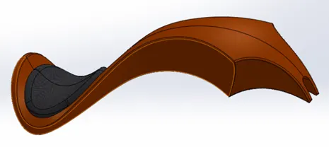
- The tank stores the fuel required to drive the engine hence it is a crucial part of the bike.
- The storage capacity in turn depends on the power of the engine & fuel efficiency.
- Features used to create
- Sketch
- Trim
- Projected curve
- Sweep surface
- Loft surface
- Fill surface
- Surface trim
- Surface knit
- Sweep cut
- Fillet
- Appearance
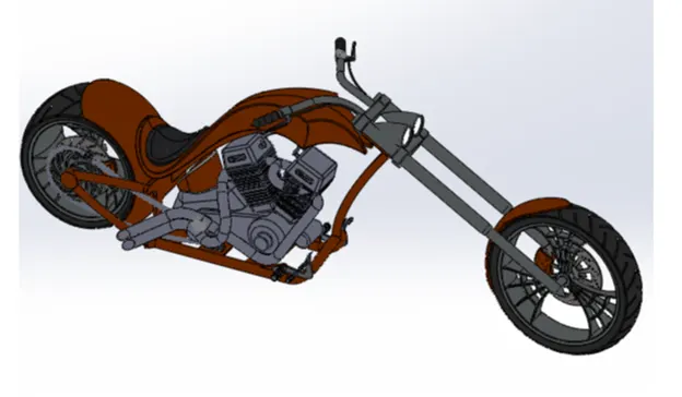
- Assembling the American chopper :
- The assembly interface uses the defined mates of the inserted bodies to position them in the main assembly and hold them together
- Mates create relations between the defined components in the assembly, some of the mates are allowable linear or rotational motion, coincident mate b/w the components, distance b/w the components etc.
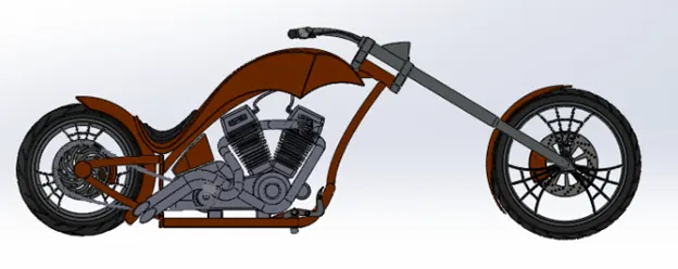
- The chassis is inserted first which forms the base of the assembly to which all the other parts are to be assembled
- Later all the other parts are inserted and assembled by giving mates with respect to the chassis position or any other component which ever define mate condition fully.
- Rendering the American chopper :
- Rendering is the process of creating photorealistic images of the 3d model
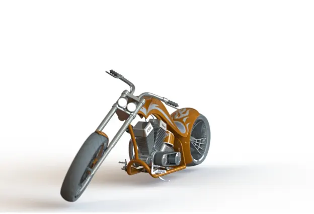
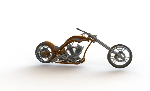
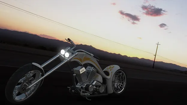
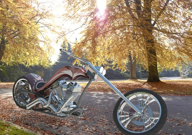
- Rendering of the chopper is done by using features available in the phot view 360 and solidworks visualize.
- In rendering interface first verified the different appearances of the of all the components.
- Then applied some decals on to the gas tank, oil tank, and rear fender to have some good style or a look on the chopper.
- The inserted some scene or backgrounds where the chopper has to be place to have realistic image.
- Then inserted the camera to adjust the view on the chopper
- Then played along with some of the cool features available like inserting lights, perspective, brightness, gamma feature, adding different scene, appearance etc.
- Photoveiw 360
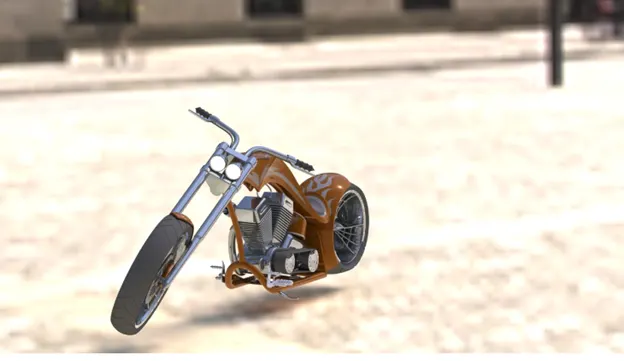
- Solidworks visualize :
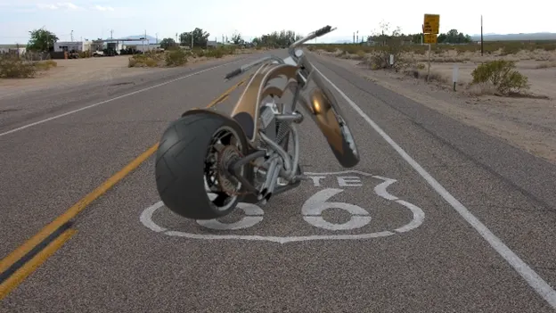
- Conclusion :
- Parts of the chopper are modelled using solidwork part modeling interface.
- The parts are then inserted in assembly interface and assembled.
- The realistic rendering is done using photoveiw 360 & solidworks visualize.