Radar Mast & Final Assembly of Yacht
ASSEMBLY & RENDERING OF YACHT
Objective-To Model Radar Mast and assemble the yacht using solid works & To Learn Surface Modelling.
Introduction-A yacht is a sailing or power vessel used for pleasure, cruising, or racing.There is no standard definition, so the term applies to such vessels that have cabin with amenities that accomodate overnight use.
Design Methodology-Here I Model & Design,
- Propeller
- Radar
- Front seat
- Middle seat
- Rear seat
- Garage door
- Hull
- Radar Mast
- Superstructure
PROPELLER-To Model Propeller, first I draw 2d sketch on right plane and apply Revolve Boss/base, then I make reference plane, draw 2 sketches and apply loft, now 135mm fillet is applied. Now 210mm Extrude cut is applied, 10mm & 30mm radius fillet is applied and circular pattern with 6no of instances is applied.
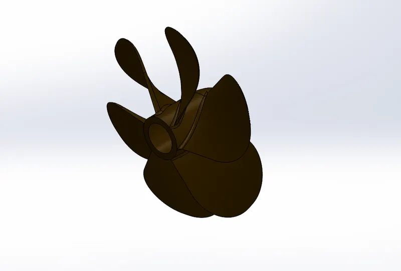
Features
Revolve-Revolve is a method of defining three-dimensional geometry by revolving a sketched section around a centerline.
RADAR-To model Radar, first I draw 2d sketch on right plane and apply boss extrude of 700mm depth, now I apply 3 fillets of radius 20mm, 30mm, and 46mm. Now I offset the sketch 3mm Outer and Extrude it depth of 10mm, Now I draw 8mm diameter circle and apply boss extrude of 3mm, fillet of 3mm radius and extrude cut of 1.5mm depth.Now I apply sketch pattern, fillet and Mirror feature.Circle of 60mm diameter is drawn and Extrude cut is applied of 40mm depth, 3mm radius fillet is applied and split feature.
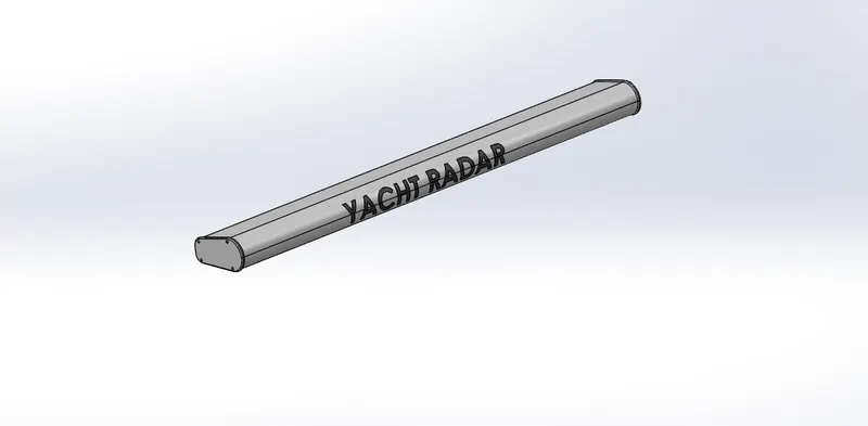
Feature
- Boss Extrude-An Extruded Boss/Base feature will allow you to take a 2D sketch and add thickness to it in the third dimension. The Extrude Boss/Base command in the Features toolbar.
- Extrude Cut-Extrude cut is used to remove material from 3D sketch by projecting 2d sketch.
- Offset-Creates a curve from an edge at a specific distance.
HULL
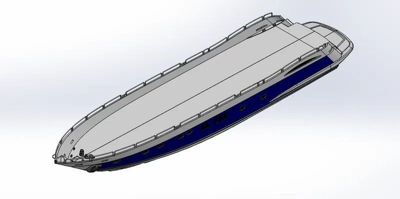
To Model Hull, first I Use Blueprint of yacht, then I draw sketches on bottom plane, and Mid plane & apply Projected curve.Again I draw 2d sketches on mid plane, and bottom plane and apply 2nd projected curve. Now Sketch is drawn on front plane & Mid plane, Surface loft is created taking Curve 1 & Curve 2 as profile and Sketch 5 & sketch 6 as Guide curve.I draw another sketches on mid plane and front plane and apply surface loft.A surface trim is applied and Another surface loft. Now I apply surface extrude of 500mm depth, Surface trim is applied to cut extra part and surface knit to combine faces.Now I use surface fill and apply 120mm thickness shell.Now I apply Boss extrude using upto next and cut extrude of depth 2724mm, another boss extrude of 3070mm depth is applied, and cut extrude of 3200mm depth.Now fillet of radius 1000mm is applied to corner edge, 30mm and 100mm radius to other edges of hull.
- Plane1-Now I make Reference Plane selecting mid plane as first reference and 5000 offset distance, Now I apply Cut extrude of 38mm offset distance and 38mm and 50mm radius fillet.Now I apply another Extrude cut of offset distance 50mm and 20mm radius fillet, Another Extrude cut of 50mm offset distance.
- Plane 2-8-A sweep is created for porthholes rings.A 2d sketch is drawn and Cut Extrude is applied using through all.
- Plane 9-10- A sweep is created for porthhole rings, Cut Extrude, and two thin Extrude is applied for stairs.Now three Boss extrude of 10mm depth and fillet of 10mm radius is applied.
- Plane 11-On plane 11, I applied Extruded boss/base, chamfer, and fillet feature.The first extrude has 75mm depth and 2nd has 30mm depth. The radius of fillet is 20mm and 800mm.
- Plane 12-On plane 12, I applied Revolve, chamfer and dome feature.
- Plane 13-On plane 13, I apply Boss extrude of 200mm depth, cut extrude of 180mm depth, fillets of 5mm & 10mm radius is applied. Helix feature with 22mm pitch, 3.65 revolution and 90degree start angle is applied.
- Plane 14-15- Sweep is created for spring, Boss extrude of 10mm, 20mm, and 60mm depth is applied, fillet of 5mm radius and linear pattern of 1100 spacing and 2 no of instances is applied.Another extrude of 10mm, 20mm, 50mm, and 60mm depth is applied, fillet of radius 5mm and linear pattern with 1200 spacing and 2 instances is applied.Now two extrude using upto next feature is applied and fillets of 5mm & 10mm radius is applied.
- Plane 16-17-On plane 17 a sweep is created for handle, now railing reference is drawn and projected curve is applied.
- Plane 18-Now a sweep is created for Railing and projected curve.
- Plane 19- A sweep is applied, Boss extrude of 100mm depth, fillets of radius 10mm, 30mm and 50mm is applied.Extrude cut of 5mm depth and fillet of 1mm radius is applied, now boss extrude using upto to next is applied and projected curve.
- Plane 20- A sweep is applied and on plane 21, Boss extrude, fillet and projected curve is applied again on Plane22 a sweep is Created.
- Plane 21- On this plane I apply 5 Boss extrudes, 2 cut extrudes, 6 fillets and 2 chamfer, the depth is 40mm, 60mm, 60mm and 400mm. The radius of fillet is 8mm, 10mm, 50mm, 3mm and 30mm.The depth of cut extrude is 100mm.
- Plane 22-First Revolve is applied then Boss Extrude of 90mm depth is applied, chamfer of 2mm distance and 45 degree angle is applied, again revolve and three chamfer is applied. now extrude boss of 25mm and 40mm depth and extrude thin of 70mm depth and 10mm thickness is applied, fillets of 5mm, 25mm and 10mm radius is applied.Pattern direction and linear pattern with 1600 spacing and 2 instances is applied.Extrude cut is applied and 3D sketch is drawn.
- Plane 23-On this plane two boss extrudes is applied and fillet of 20mm radius is applied, the depth is 1650mm and offset distance is 20mm.
- Plane 24-25- Boss extrudes of 50mm, 100mm, 140mm, 80mm, 50mm, 150mm depth is applied, Extrude thin and Cut extrude thin is applied of 1800mm depth and 5mm thickness and thin extrude of 10mm thickness is applied.Fillets and Chamfers also applied, Extrude cut of 5mm and 600mm depth is applied. Now mirror and split feature applies. A split line is created, In last I apply Deck surface and Mirror Features and Combine. Features
- Boss Extrude
- Cut Extrude
- Surface loft
- Surface fill
- Surface Extrude
- Sweep
- Split
- Thin Extrude
- Linear pattern
- Pattern direction
FRONT SEAT
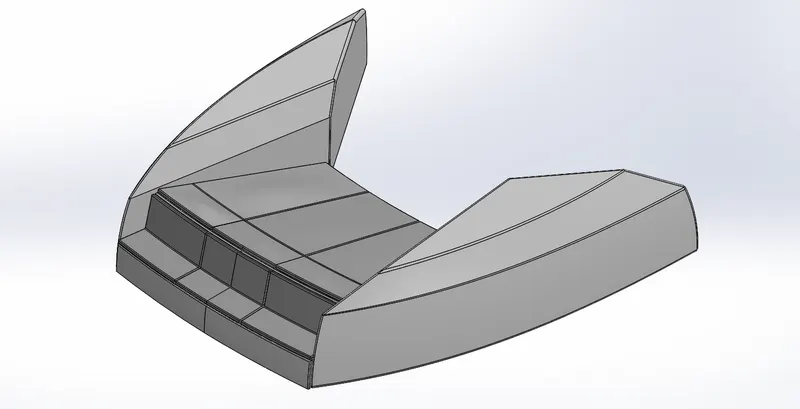
To Model Front seat first I Apply Surface feature like surface sweep, surface Extrude, Surface fill, Surface trim, Surface knit, surface Extrude then I apply Chamfer, Revolve, fillet, Dome,Mirror and Cut Extrude features. The depth of extrude cut is 600mm, 6000mm, and 5mm. cut extrude thin is applied of 2.5mm thickness.Fillets of 10mm and 30mm radius is applied to all inside and outside edges. Dome of 30mm is applied on seats and also Mirror is applied.
Features
- Surface fill
- Surface knit
- Surface Extrude
- Revolve
- Dome
- Mirror
MIDDLE SEATS
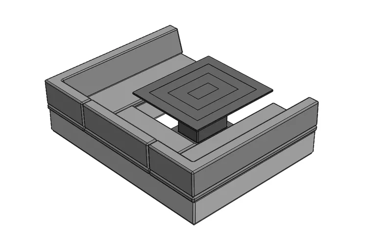
To Model Middle seats first I use Blueprint then apply boss extrude of 35mm and 300mm depth, Now make reference plane and apply boss extrude of 70mm depth, again reference plane is made and boss extrude of 350mm depth is applied.Chamfer is applied with 100mm and 350mm distance, 20mm radius fillet is applied to all edges. Now Mirror is applied. Boss extrude of 20mm depth, and 550mm depth is applied. extrude cut of 0.5mm depth and fillets of radius 5mm and 20mm is applied.
Features
- Boss extrude
- Extrude cut
- Chamfer
REAR SEATS
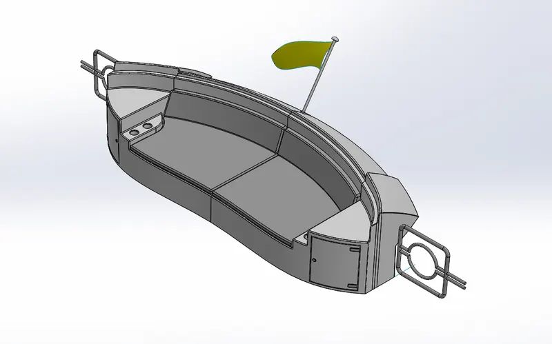
To Model Rear seat I use Blueprint first then I create Surface sweep and Surface offset of 50mm. Now Surface trim is applied and Ruled surface of 150mm distance now Surface knit and surface trim is applied.
Plane 2 & 3-Surface sweep is created, Surface extend of 200mm is applied, Surface trims and Surface knits is applied.Surface Extrude of 1200mm depth is applied, now surface trims, surface knits, surface lofts is applied. again surface Extrude, surface loft, surface trim, and surface knit is applied.Now Extend the surface with 20mm and 50mm distance,surface trim is applied.Boss extrude of 350mm and 310mm depth is applied, Cut extrude of 50mm and boss extrude of 120mm depth is applied. extrude cut of 90mm depth and chamfer of 45degree angle and 7mm distance is applied.
Plane 4-First Boss extrude is applied of 5mm offset distance, now surface offset is applied of 5mm offset direction, surface trim is applied and boss extrude of 60mm depth applied again surface offset is applied of 5mm, surface trim applied and Boss extrude of 300mm depth is applied.Chamfer is applied with 110mm and 307mm distance. fillet is applied of 3mm, 5mm, 8mm, 10mm, 15mm, and 20mm radius. 5mm depth extrude is applied for lights and 2mm radius fillets.
Plane5-6-A 2d sketch is drawn for sweep for gate and on Plane 7 again sweep is applied and fours Mirrors are applied.In last Revolve feature is applied for flag. fillet of 40mm radius is applied Chamfer of 20mm and 3mm distance is applied, a 3d sketch is drawn and surface loft is applied.
Features-
- Surface sweep
- Surface extend
- Surface trim
- Surface knit
- Ruled surface
- Extruded cut
GARAGE DOOR
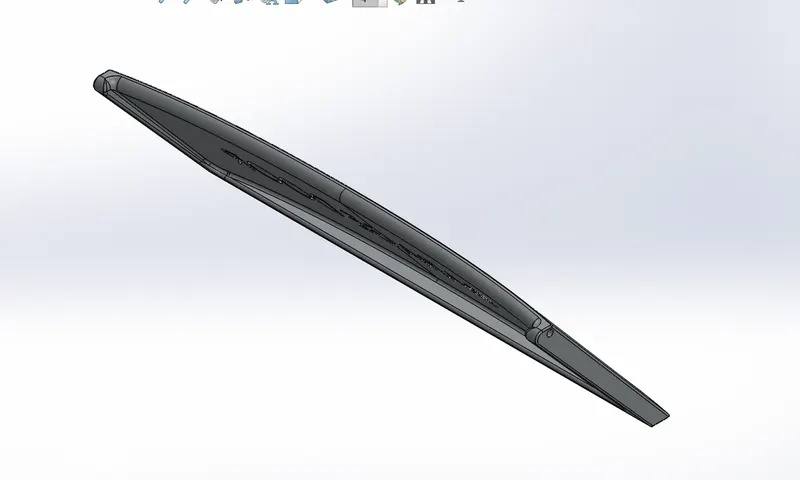
To model garage door first I apply extrude cut using through all, now 100mm shell is applied, fillets of 15mm and 100mm radius is applied, again cut extrude is applied of 100mm depth for pin holes, now fillet of 10mm and 15mm radius is applied.now mirror feature applied.Reference Plane is created and cut extrude of 8mm depth applied.
Features
- Extrude cut
- Shell
SUPERSTRUCTURE
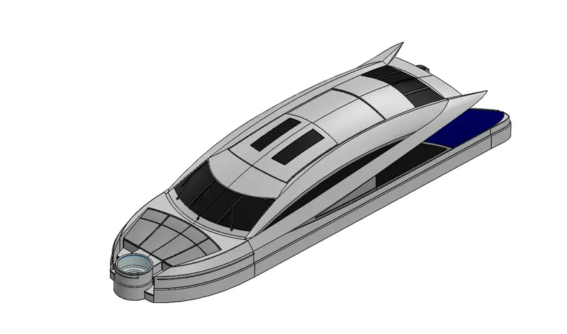
To Model Superstructure first I open blueprint of yacht then I Use Deck surface of hull, and apply Surface Extrude, Surface sweep, Surface loft, surface knit, Ruled Surface , projected curves, Surface fill,Surface knit on Planes 1, Again make Reference plane 2, 3, 4, 5 upto 14 and apply same features like 3d sketch, Surface fill, Surface extend, surface offset, Cut extrude, Boss extrude, Thicken, extrude thin, Dome, fillets and Mirror to make Remaining parts of superstructure. All Feature used here is Surface Modelling feature.
Features
- Surface loft-Loft surfaces are surfaces generated by multiple 3D Curves or Existing edges Creating a smooth tangency between the selected curves.
- Ruled surface-Ruled surface is normal to the surfaces that sharp an edge. Ruled surface is tapered to the specific vector. Ruled surface is perpendicular to the specified vector.Ruled surface is built by creating a swept surface using selecting edges as guide curves.
- Surface offset-The offset surface tool creates a new surface body from an existing set of faces.The face may be solid or surface face.
RADAR MAST-To model radar mast, I take superstructure surface body, then I create a line and make reference plane, selecting line as 1st reference and mid plane as 2nd, now I apply Boss extrude and fillets. Again I make 2nd Plane and apply all features to make antenna and plane 3,4 and 5 to make all Remaining parts of Radar mast like Horn, lights etc and apply mirror.
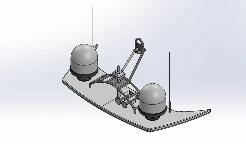
Features
- Boss Extrude
- Sweep
- Shell
- Fillets
Adding decals on the Hull-Now I add decals on Hulls, main floor, Hatch and on stairs
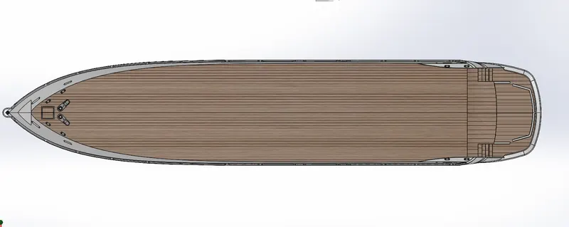
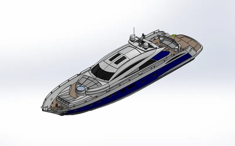
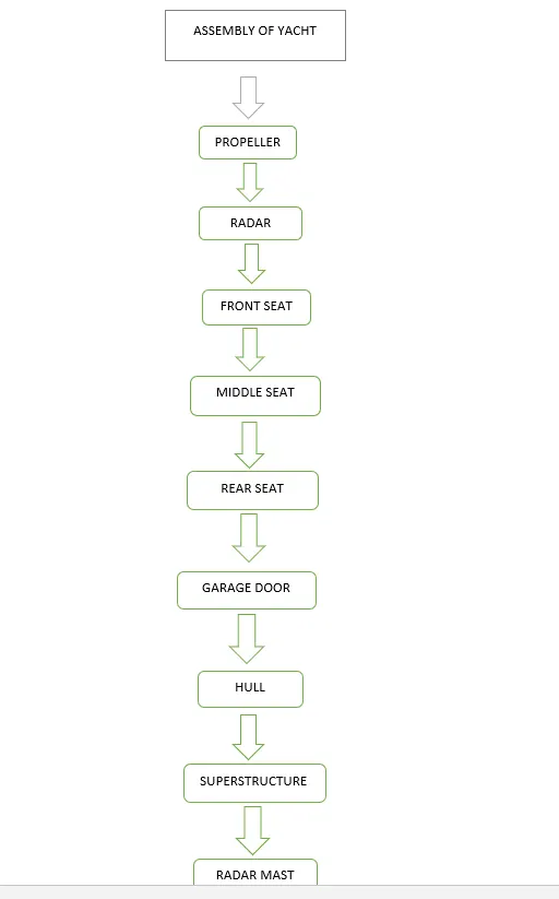
ASSEMBLY OF YACHT-Now After Modelling all parts of yacht, I assemble all parts of yacht using Coincident mates, and Concentric mates.
Rendering Of Yacht-Now I Rendered the yacht using Photoview 360 in Isometric view, top view, front view, Side view, and Camera view.
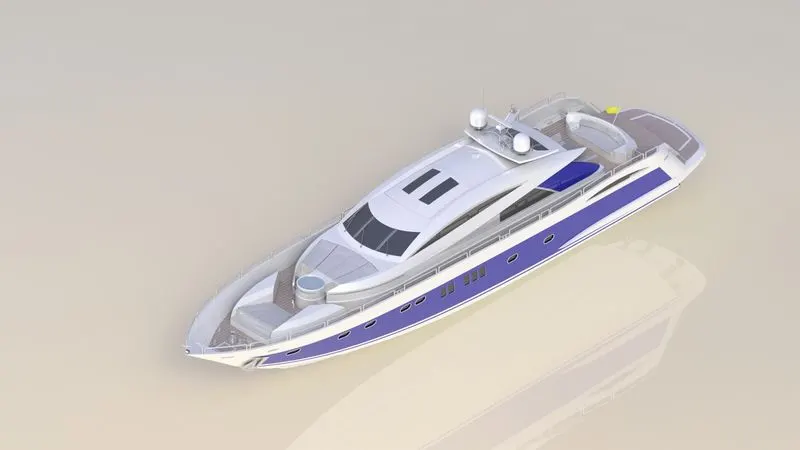
Isometric View
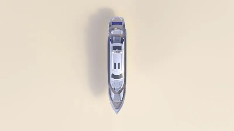
Top View
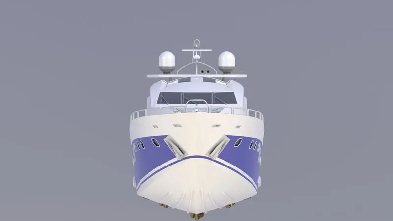
Front view
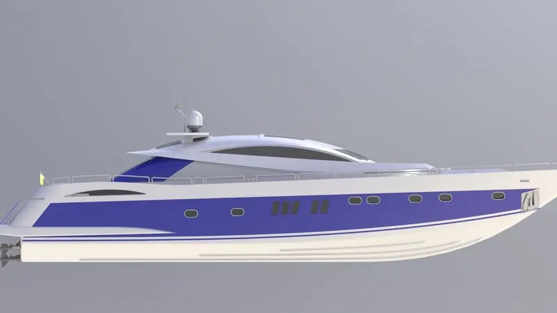
Side view
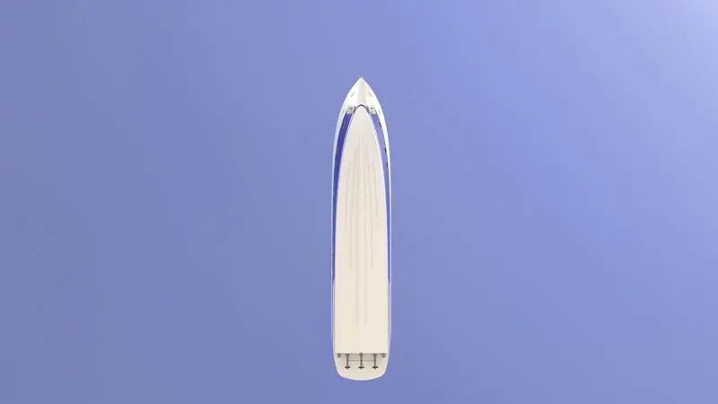
Bottom view
FLOWCHART
CONCLUSION-I Successfully Completed Modeling of all parts of yacht, and Assembly & rendering of the yacht in Solid works 2020.