Radar Mast & Final Assembly of Yacht
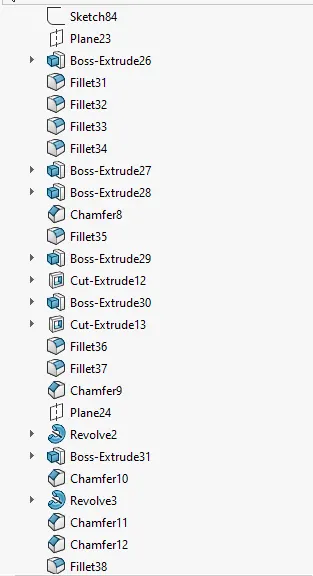
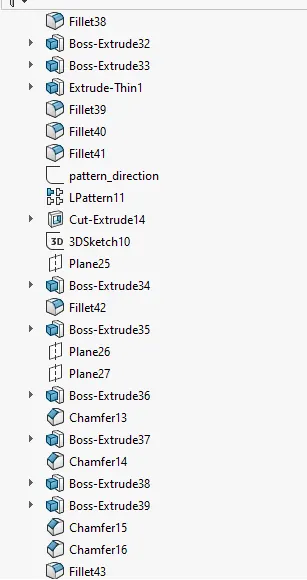
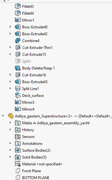
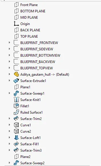
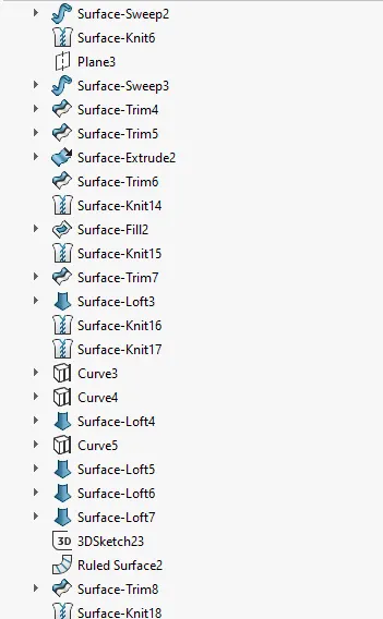
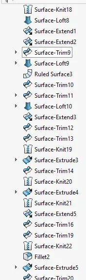
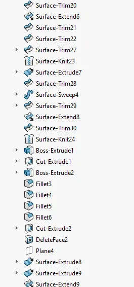
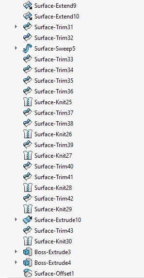
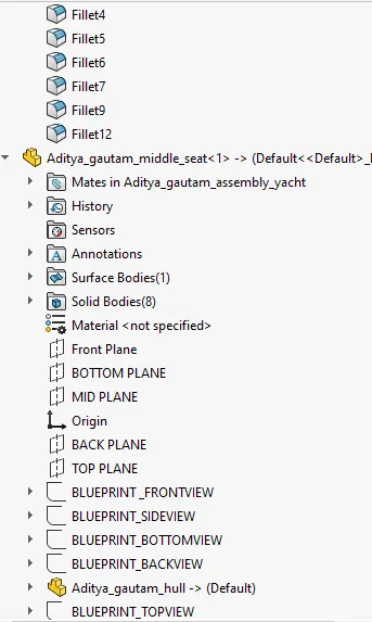
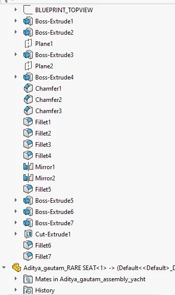
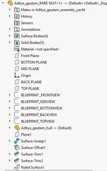
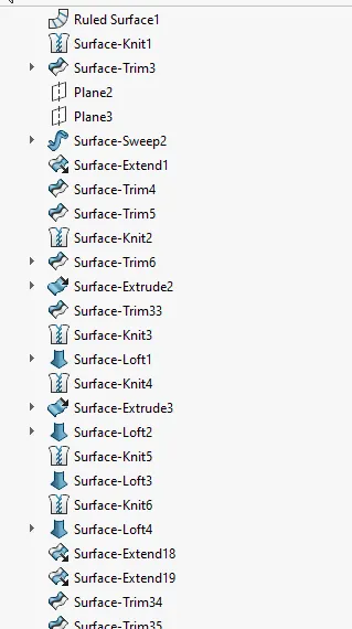
REPORT
ON
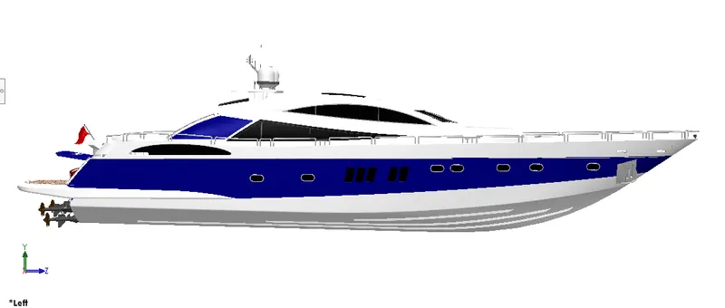
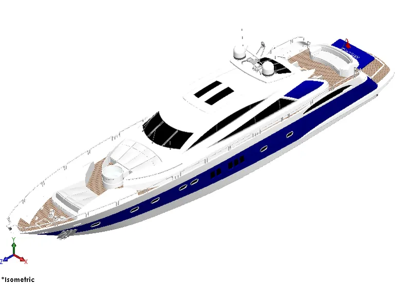
Modelling and Assembly of an American Predator Yacht
INTRODUCTION
SolidWorks is a solid modeling computer-aided design and computer-aided engineering software developed by Dassault Systems, used for modelling components in automotive, aeronautics and many other industries. It is a parametric modeling software due to which it is very easy to make configuration to the model in SolidWorks.
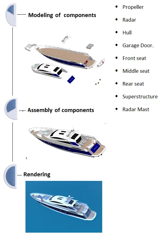
In this project an American Predator Yacht is designed using SolidWorks. The yacht consists of different components such as:
- Propeller
- Radar
- Hull
- Garage Door.
- Front seat
- Middle seat
- Rear seat
- Superstructure
- Radar Mast
These components designed separately in different part files by making use of different features of SolidWorks such as sketches, extrudes, filled surfaces, ruled surfaces, surface trims, surface knit, surface extrudes, lofts, reference planes, projected curves etc. followed by definition of material for each component.
After modeling of each component, each part is brought to one assembly file and then assembled by providing required constraints or mates relation to each component in assembly environment of the SolidWorks.
The assembled yacht is then rendered using PhotoView 360 and SolidWorks Visualize. PhotoView 360 is an add-in built in SolidWorks which can make high quality photorealistic renderings with real-time appearances and views whereas SolidWorks Visualize is a software to make render by placing objects in an environment.
Objective
- The aim of this project is to design the parts of an American yacht in SolidWorks software
- Assemble all the parts in SolidWorks assembly.
- Render photorealistic images of the yacht using PhotoView 360.
- Render images of the yacht by setting up in the environment in SolidWorks Visualize.
Design Process
The design process involves the following steps:
- Identify the model requirements.
- Conceptualize the model based on the identified needs.
- Develop the model based on the concepts.
- Analyze the model.
- Prototype the model.
- Construct the model.
- Edit the model, if needed
Design Methodology
Design Tools Overview
Sketch tools: The sketch is the basis for most 3D models, creating a model usually begins with a sketch.
- Line: used to create line, depending on its use can be used as normal line or construction or midpoint.
- Circle: This command is used to create circles in solid works
- Rectangle: used to create rectangle
- Arc: used to make an arc.
- Spline: used to make a line whose curvature can be adjusted.
- Slot: used to create a slot
- Mirror Entities: used to make a copy of the sketch along a reference plane/axis/line.
- Offset entities: Offset one or more sketch entities, selected model edges, or model faces by a specified distance.
- Trim entities: trims a sketch entity to be coincident to another.
- Convert entities: create one or more curves in a sketch by projecting an edge, loop, face, curve, or external sketch contour, set of edges, or set of sketch curves onto the sketch plane.
- Smart Dimension: used to add dimensions to the sketch profile
Feature tools:
- Extrude Boss: used to extrude selected sketch contour to create a solid body.
- Extrude Cut: cuts a solid model by extruding a sketched profile
- Revolve Bose: create a solid body from sketch around an axis.
- Revolve cut: cuts a solid body by revolving a sketched profile around an axis.
- Swept: sweeps a closed profile along an open or close path to create a solid feature.
- Swept cut: cuts long a swept axis in a solid body.
- Shell: removes material from a solid body to create a thin-walled feature.
- Split: create multiple body from a single body.
- Linear Pattern: Used for making linear patterns for solid bodies or cuts along a reference line.
- Circular Pattern: used for making circular pattern of solid bodies or cuts along a reference axis of a circular reference geometry.
- Curve Driven Pattern: used to make a pattern of solid bodies or cuts along an uneven curve.
- Fillet: used to make a rounded faces internally or externally on the edges of the body or sketch.
- Chamfer: used for making inclined faces on the edges of the solid body.
- Mirror: used to make copy of the solid body along a reference plane/axis/line.
- Reference geometry: used for creating reference planes, axis, etc.
- Projected curves: This is used to make uneven or curves which follow certain path using two or more reference curves.
- Dome: used to add a dome to planar or non-planar surface
- Loft: used to add material between two or more profiles to make solid bodies
Surface tools
- Extruded Surface: used to create a surface from a line.
- Revolve Surface: used to create a revolved surface.
- Swept Surface: used to create sweep on uneven lines or curves.
- Lofted Surface: used to create surface lofts.
- Boundary Surface: used to create surfaces from the boundary
- Split line: used to creates a sketch on curved or planar surfaces
- Filled surface: fills in surface within a closed boundary by the selection of guide curves.
- Ruled surface: creates a ruled surface from selected edges.
- OFFSET SURFACE - It creates a surface in compliance with the profile selection.
- SWEEP SURFACE - It creates a surface by sweeping an open or closed surface along an open or closed path.
- TRIM SURFACE - It trims the surface selection considering cutting edge as a trim tool.
- SURFACE KNIT - It combines two or more adjacent surfaces together.
Sketch relations
- Coincident: This relation makes two points of two line or a point and line coincident with each other.
- Parallel: This makes two lines parallel to each other.
- Perpendicular: This makes the two lines perpendicular.
- Vertical: This is used to make lines vertical with respect to the origin
- Equal: For making lines, circles equal to each other.
- Concentric: This relation makes two circle or a point and a circle concentric.
- Tangent: To make lines and arc tangent.
- Horizontal: This relation makes lines horizontal to origin. This is also used for making two points or point and a line horizontal.
- Make Pierce: To attach the center point of and ellipse or circle to the line
Appearances
An appearance defines the visual properties of a model, including color and texture. Appearances do not affect physical properties, which are defined by materials. Every material is assigned a default appearance that emulates the look of the material.
Render tools
- Edit appearance: edit the appearance of entities in the model
- Copy appearance: copy the appearance of entities in the model
- Paste appearance: paste the appearance to entities in the model
- Edit scene: edit the scene applied to the document
- Edit decal: applies decals to the faces in a model.
- Preview window: opens the photoview 360 preview window which is a real-time rendering process of how the model look after final rendering
- Final rendering: it invokes a photoview 360 final rendering which is the high-quality rendering.
- Options: it is a setting option which promotes editing the photoview 360 rendering.
Assembly tools
- Edit component: toggles between editing a part or a subassembly and the main assembly
- Inset component: adds an existing part or subassembly to the assembly.
- Linear component pattern: pattern components in one or two linear directions.
- Circular component pattern: pattern components in radial directions
- Mate: create geometric relationships between assembly components by positioning components relative to one another.
- Exploded view: separates the components into an exploded view.
DESCRIPTION:
In SolidWorks the very first step for modeling any component is to begin with selection of plane in which the sketch profile is drawn as per the required design approach followed by feature tools such as extrude boss to convert any 2d sketch to solid body. Using similar operation different parts of the yacht are as followed: -
- Modeling of propeller
A propeller is a device with a rotating hub and radiating blades that are set at a pitch to form a helical spiral, that, when rotated, exerts linear thrust upon a working fluid, such as water or air. The blades are specially shaped so that their rotational motion through the fluid causes a pressure difference between the two surfaces of the blade by Bernoulli's principle which exerts force on the fluid.
Design overview:
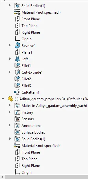
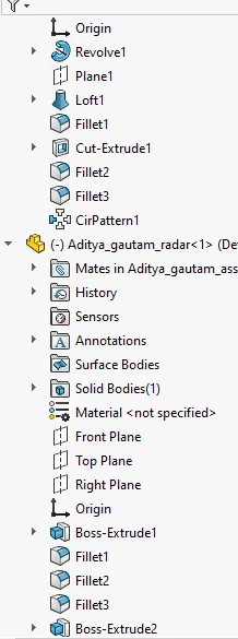
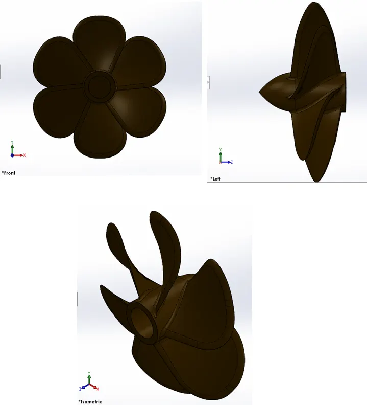
The propeller of this yatch is modeled by creating a sketch on right plane followed by revolve to convert it into 3d solid body and then sketch on top plane & a reference plane is created, using loft the blade is created followed by fillet and then the circular pattern is used for wings using the centre of solid body as reference to get required propeller. Finally the fillets are added at required spots in body.
Design tools used:
- Sketch
- Line
- circle
- Rectangle
- Loft
- Revolve
- Circular Pattern
- Fillet
- Extrude cut
RENDER IMAGE
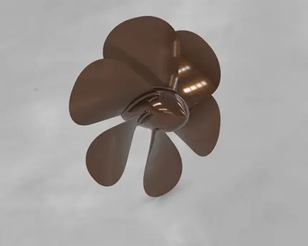
Different views of the model:
- Modeling of radar
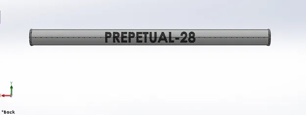
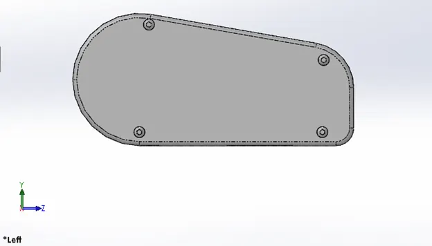
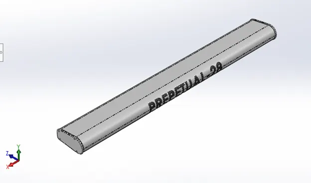
Radar is a vital navigation component for safety at sea and near the shore. Captains need to be able to maneuver their ships within feet in the worst of conditions and to be able to navigate "blind", when there is no visibility at night or due to bad weather. They are electronic navigation instruments that use a rotating antenna to sweep a narrow beam of microwaves around the water surface surrounding the ship to the horizon, detecting targets by microwaves reflected from them, generating a picture of the ship's surroundings on a display screen.
Design overview:
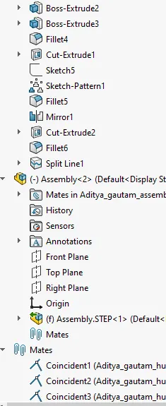
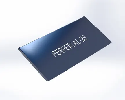
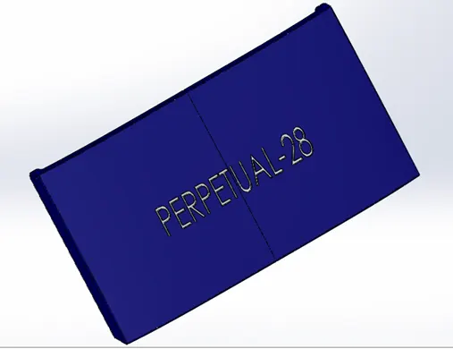
The half of radar of the yacht is modeled due to its symmetricity. Then the created one side of the radar is mirrored and while mirroring enable merge solids option so that they formed single solid body. After creating we can add text to radar if needed to get more realistic. Using split line the text is projected on to Radar body.
Design tools used:
- Sketch
- Extrude
- Fillet
- Line
- Polygon
- Circle
- Text
- Spilt line
- Mirror
RENDER IMAGE:
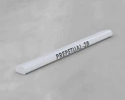
Different views of the model:
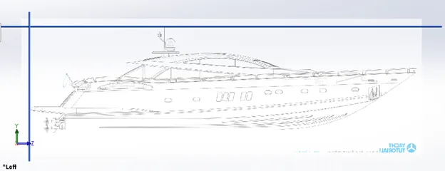
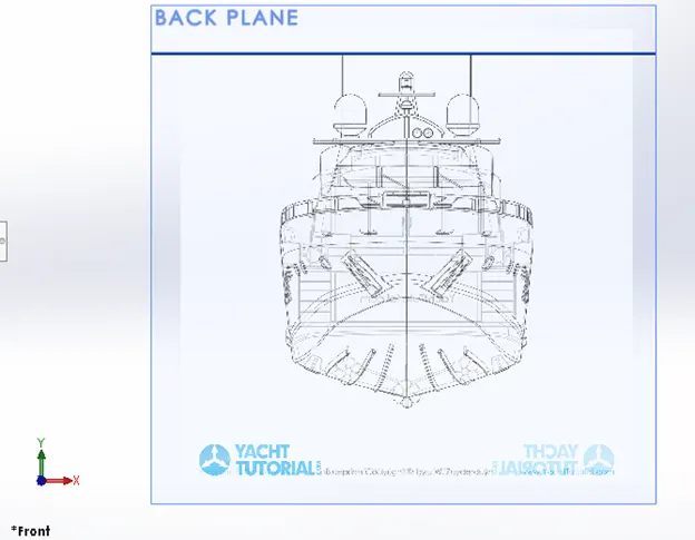
- Setup of blueprint
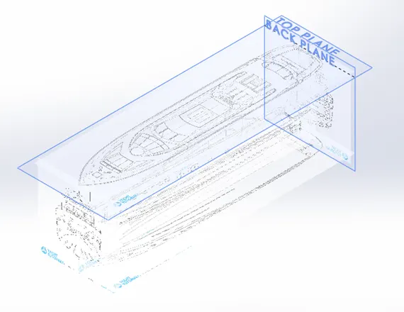
A blueprint is a guide for making something — it's a design or pattern that can be followed. A photographic print in white on a bright blue ground or blue on a white ground used especially for copying maps, mechanical drawings, and architects' plans.
Design overview:
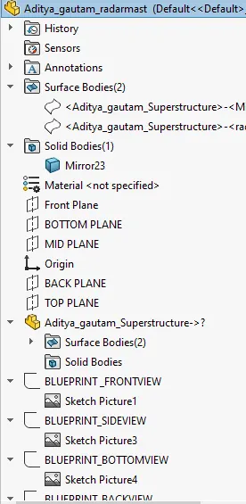
In solidworks we import blueprint images in different planes and save them in sketch environments followed by resizing them and defining the image such that origin for all images be same, which are then used as a reference for creating the complete 3d model.
Design tools used:
- Sketch picture
- Modeling for hull
A hull is the watertight body of a ship, boat, or flying boat. The hull may open at the top (such as a dinghy), or it may be fully or partially covered with a deck. Atop the deck may be a deckhouse and other superstructures, such as a funnel, derrick, or mast. The line where the hull meets the water surface is called the waterline.
Design overview:
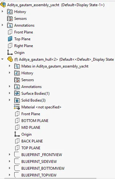
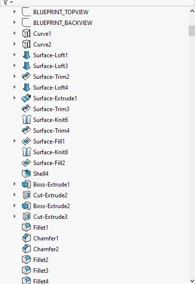
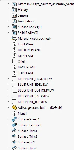
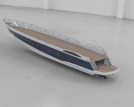
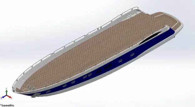
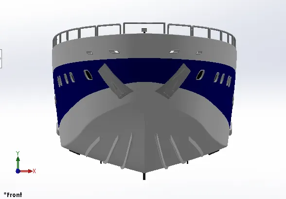
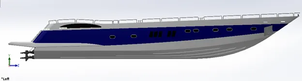
The hull is modeled using surface modeling. In this case too half side of hull is modeled and mirrored about midplane at later part due to its symmetricity. The complete body is created by the use of projected curves and reference planes followed by operation like Lofted surface, boundary surface, extrude surface, trim surface, While the port holes are created using extrude cut and swept boss.
At the end the fillets are added at required places to get more clear views and also to remove the material. After creating the one side, mirror it to other side and knit the surfaces properly. Finally the decals are added on deck surface and stairs and also appearances are changed at places for clear view.
Tools and Features used:
- Sketch
- Line
- Circle
- Projected Curves
- Linear Pattern
- Mirror
- Surface Extrude
- Surface Loft
- Extrude Cut
- Fillet
- Chamfer
- Sweep
- Surface Knit
- Surface Trim
- Offset
- 3D Sketch
- Plane
- Shell
- Split
RENDER IMAGE:
Different views of the model:
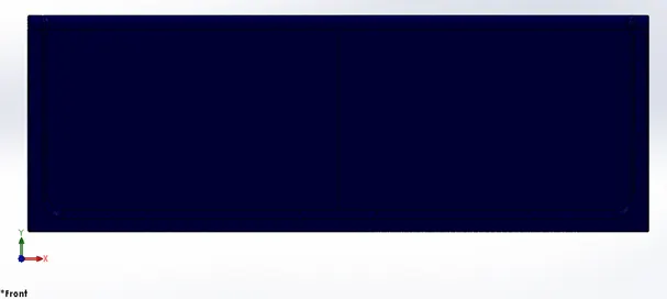
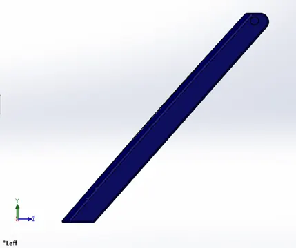
- Modeling of garage door
Garage door is a large door on a garage in the yacht large enough to accommodate automobiles and other vehicles. Making garage a safe place for automobiles and for storing things.
Design overview:
Garage door is simply modeled by just removed the unwanted portion of hull surface using extrude cut feature and saving that part separately so that we do not require any dimensions while creating it. Add fillets at sharp ends.
Design tool used:
- Extrude cut
- Mirror
- Text
- Split line
- fillet
- shell
RENDER IMAGE:
Different views of the model:
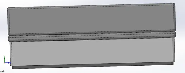
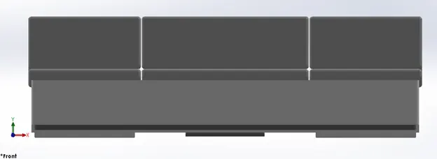
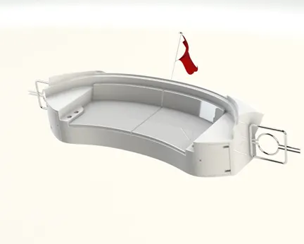
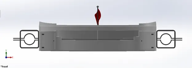
- Modeling of Seat
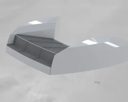
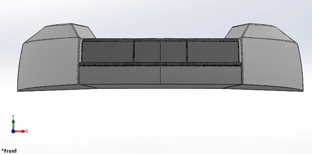
Seats are provided in the yacht for the passengers to sitting and enjoy the view. As per need the seats in yacht are provided in three different position and are accordingly designed.
Seats according to the position in yacht are named as:
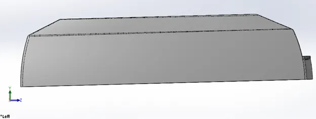
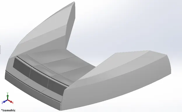
- Front seat
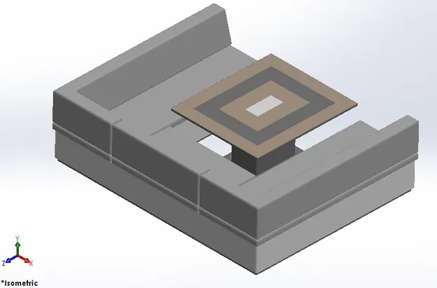
- Middle seat
- Rare seat
Design overview:
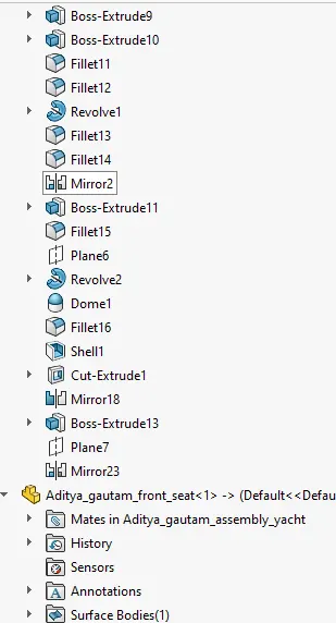
The modeling of seats includes some features of surface modeling and some of solid modeling. In these reference planes are added where ever required and fillets, chamfer to added to get more realistic view. Finally the appearances are added for color and materials of seat to view clearly.
Design tools used:
- sketch entities
- surface sweep
- surface extrude
- trim surface
- surface fill
- surface loft
- knit
- chamfer
- fillet
- revolve
- knit surfaces
- extrude cut
- dome
- mirror
Front seat:
- Rendered image:
Different views of the model:
Middle seat
- Rendered image:
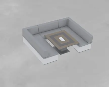
Different views of the model:
Rare seat
- Rendered image:
Different views of the model:
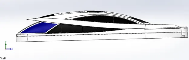
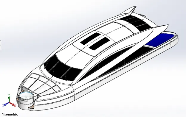
- Modeling for superstructure
A superstructure is a decked structure on the freeboard deck, extending from side to side of the ship. It is basically an extended construction of any building or platform that rises above the rest of the building or platform in a distinct manner. They are designed in a manner, so that, they add value and hinder the speed and mobility in the least.
It is the accommodation, offices, the navigation bridge, the signalling and communication units, utility spaces and multifarious electrical and electronic system areas, which are indispensable to the operation and the functionality of the ship as well as the sustainability of crew.
Design overview:
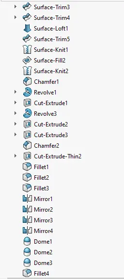
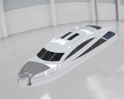
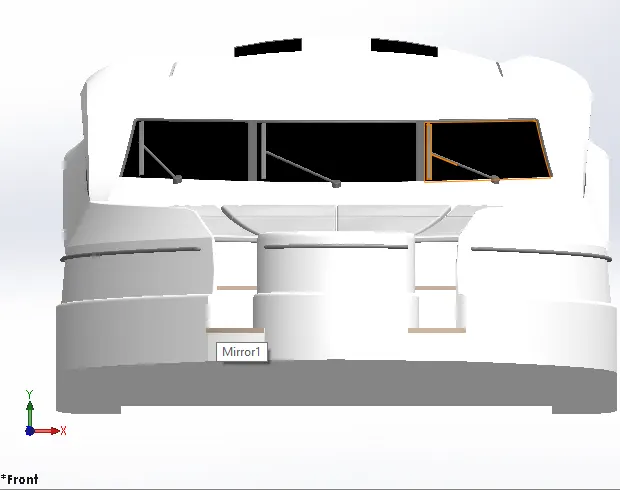
The deck surface of hull is imported. This helps in assembly of yacht so that it gets assemble directly without any required mates. In this case too half side of superstructure is modeled and mirrored about midplane at later part due to its symmetricity. The surfaces of superstructure are created with major use of projected curves, reference planes, surface knit, surface trim, 3d sketch, surface loft. Fillets, chamfer are applied to the edges of the superstructure. Appearances are also changed. The Jacuzzi also created and is kept transparent to show the water level.
Design tools used:
- line
- spline
- circle
- extrude cut
- Projected curves
- Offset
- Surface fill
- surface Extrude
- Surface sweep
- Dome
- Surface Trim
- Extend Surface
- Surface Knit
- Plane
- Ruled Surfaces
- Split Entities
- Split Lines
- Delete Faces
- Fillet
- Chamfer
- Mirror
Render image:
- Different views of the model:
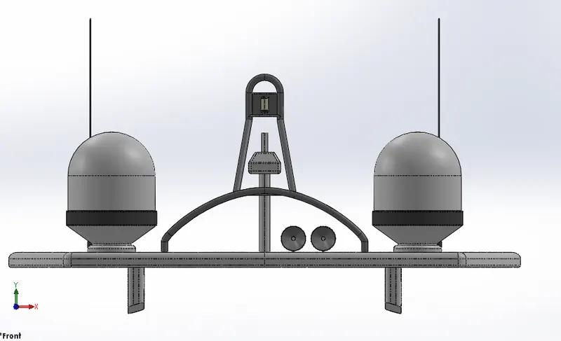
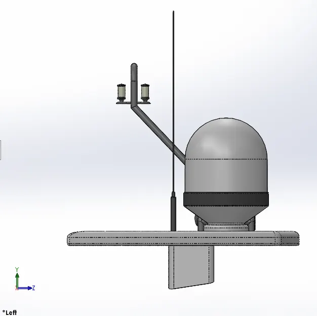
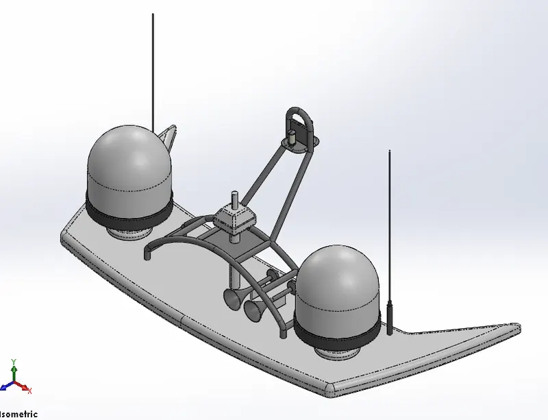
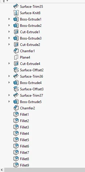
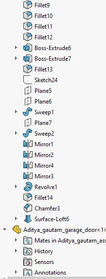
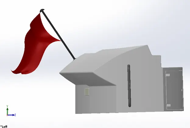
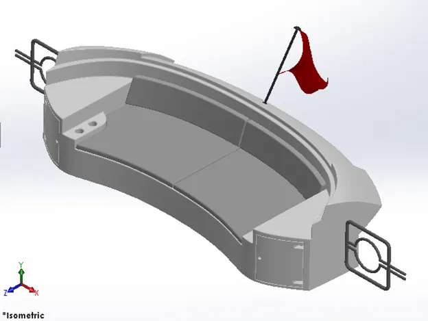
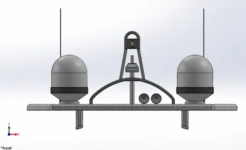
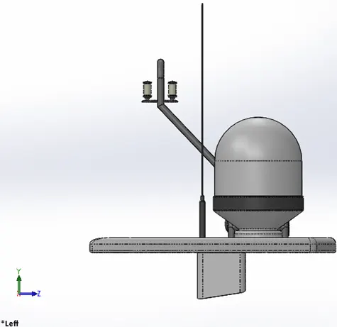
- Modeling of radar mast
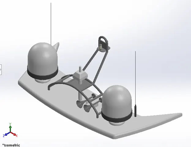
The Mast of a sailing vessel is a tall spar, or arrangement of spars, erected more or less vertically on the centre-line of a ship or boat. Its purposes include carrying sails, spars, and derricks, and giving necessary height to a navigation light, look-out position, signal yard, control position, radio aerial or signal lamp. Large ships have several masts, with the size and configuration depending on the style of ship.
Design overview:
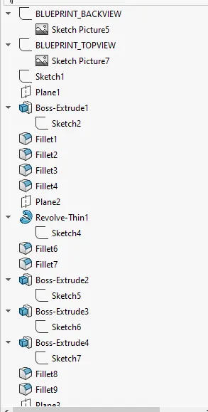
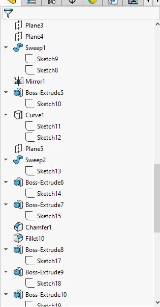
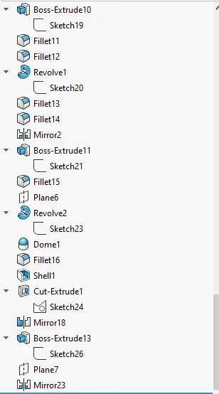
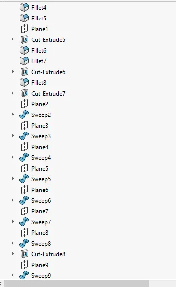
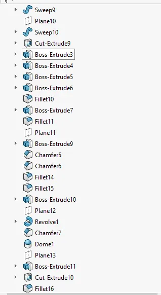
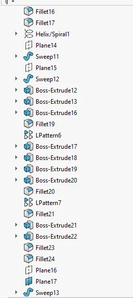
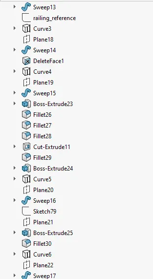
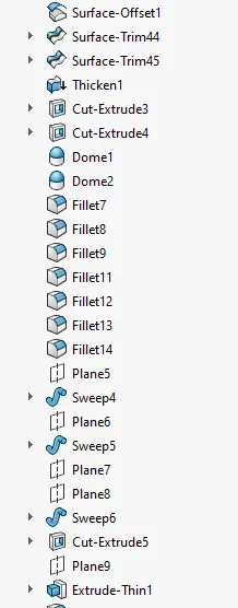
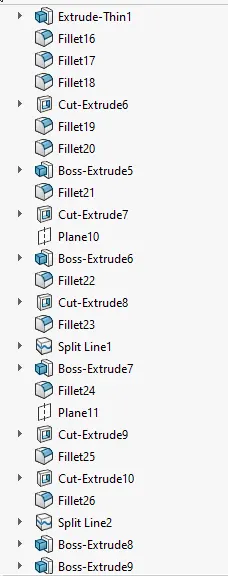
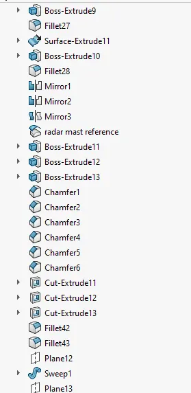
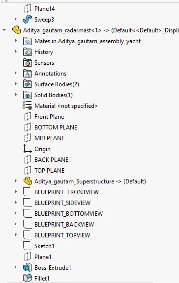
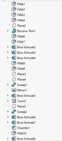
The surface of superstructure as interface is imported as it helps in assembly of yacht so that it gets assemble directly without any required mates. Again as done in other components half side of radar mast is created using features like extrude boss ,extrude cut, fillets, chamfer, swept , revolve. All features are used to create one side of the radar mast and then simply mirrored as it is symmetric. Also there are 2 horns on radar mast which are created using shell, revolve features and add dome, fillets. At last appearances are added to change color where ever required to get realistic view.
Design tools used:
- Spline
- Extrude Bose
- Revolve
- Circle
- Mirror
- Line
- Mirror
- Fillet
- Chamfer
- shell
- projected curve
Render images:
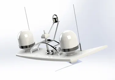
- Different views of the model:
- Assembly of American yacht
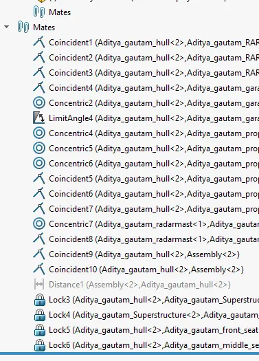
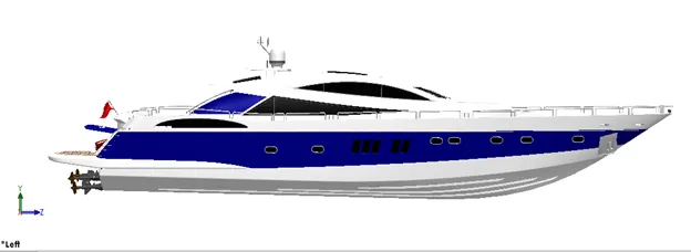
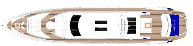
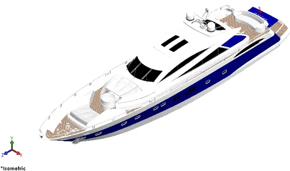
After all, the components of the American yacht are designed in the part design environment, assembly is then created form the part files. In SOLIDWORKS, the feature which connects or joins two different components is called mate. The parts are imported into the Assembly environment and then required mates are applied to each individual part with respect to the connecting part. The first part inserted into the assembly is always fixed by default.
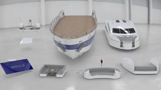
The very first part imported is the hull which act as a base for all other components. All the components imported except the radar, propeller and the garage door will get directly fixed to there position on the deck of hull. You can also apply mates relation by floating all the fixed parts and provide relation with respect to the hull if you like to orient the yacht for rendering purpose in different environment.
Different views of the assembly
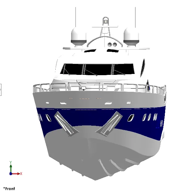
FRONT VIEW
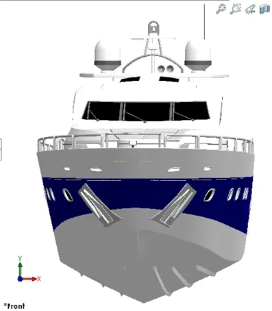
SIDE VIEW
TOP VIEW
ISOMETRIC VIEW
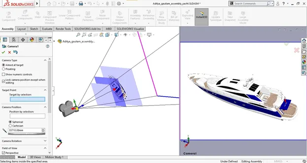
CAMERA-SETUP VIEW
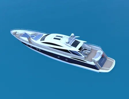
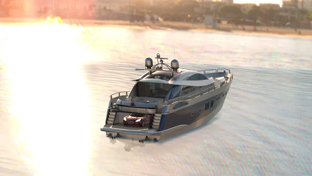
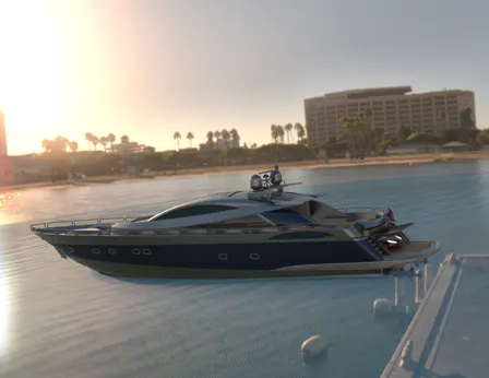
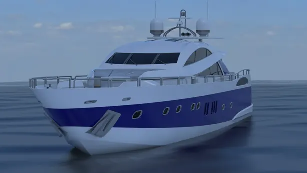
- Render of the American YACHT
Rendering is done by designer to obtain a photo-realistic image out of the 3d model created on any CAD software. This helps the designer have a better understanding of his design will look in real world. For proper rendering, there is a need to set up the correct scene, light, camera views and decals if necessary.
In SolidWorks rendering can be done by two mediums:
- Photo View 360 which is one of the add-ons of SolidWorks
- ‘SOLIDWORKS Visualize’ is another powerful tool of SOLIDWORKS which comes as separate software
SolidWorks visualize produces high quality renders compared to photo view 360.
Rendering Process:
The rendering process includes the following steps:
- Apply scene
- Apply lights
- Apply decals
- Adjust camera view
- Adjust image quality
- Render
After the rendering is complete, the rendered images are used for presentation purposes.
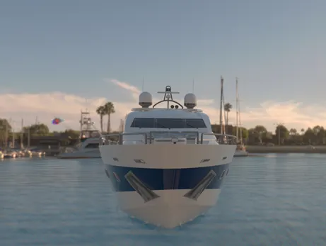
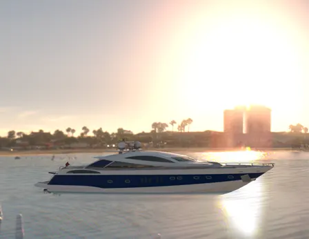
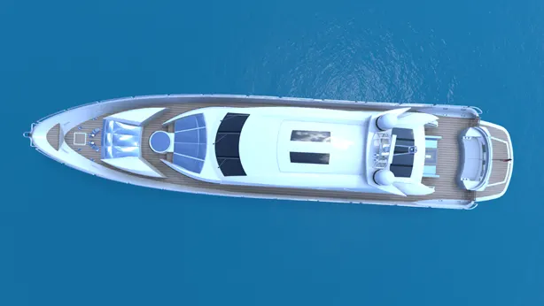
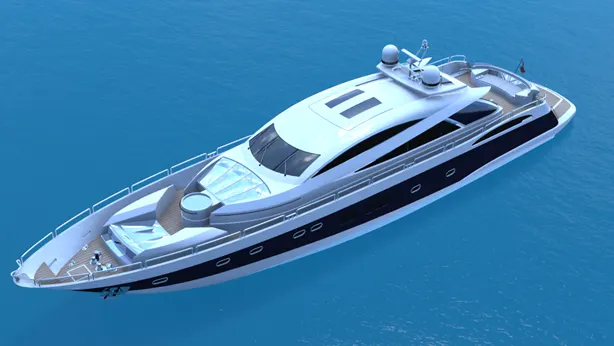
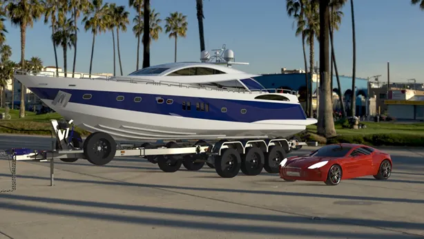
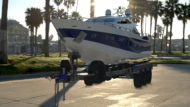
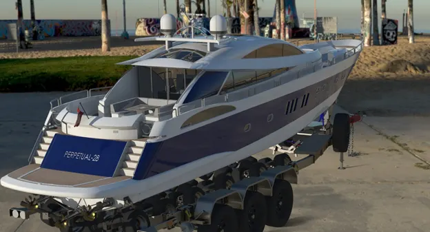
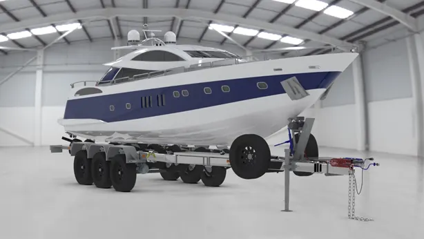
Different rendered views of Yacht in different environment
FRONT VIEW
SIDE VIEW
TOP VIEW
ISOMETRIC VIEW
CAMERA-SETUP VIEW
SOME MORE RENDERS
- conclusion:
The design, assembly, and rendering of an American YACHT is done using SOLIDWORKS. The project has enhanced my designing skills, surfacing skills during whole journey of making of the American YACHT. Through this project one can learn how to approach a design in an effective manner and end up with an industry ready product design. All over the project was successful.