Photo Realistic Rendering
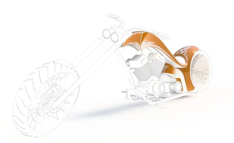
Designing, Modelling, Assembly and Photo-realistic Rendering of an American Chopper
Objective
- The aim of this project is to design the parts of an American chopper in SolidWorks software
- Assemble all the parts in SolidWorks assembly.
- Render photorealistic images of the chopper using PhotoView 360.
- Render images of the chopper by setting up in the environment in SolidWorks Visualize.
INTRODUCTION
SolidWorks is a solid modeling computer-aided design and computer-aided engineering software developed by Dassault Systems, used for modelling components in automotive, aeronautics and many other industries. It is a parametric modeling software due to which it is very easy to make configuration to the model in SolidWorks.
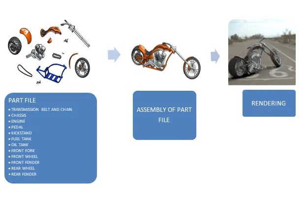
In this project an American chopper is designed using SolidWorks. The chopper consists of different components such as:
- TRANSMISSION BELT AND CHAIN
- CHASSIS
- ENGINE
- PEDAL
- KICKSTAND
- FUEL TANK
- OIL TANK
- FRONT FORK
- FRONT WHEEL
- FRONT FENDER
- REAR WHEEL
- REAR FENDER
These components designed separately in different part files by making use of different features of SolidWorks such as sketches, extrudes, cut extrudes, revolve cuts, lofts, circular patterns, reference planes, etc. followed by definition of material for each component.
After modeling of each component, each part is brought to one assembly file and then assembled by providing required constraints or mates relation to each component in assembly environment of the SolidWorks.
The assembled chopper is then rendered using PhotoView 360 and SolidWorks Visualize. PhotoView 360 is an add-in built in SolidWorks which can make high quality photorealistic renderings with real-time appearances and views whereas SolidWorks Visualize is a software to make render by placing objects in an environment.
Design Process
The design process involves the following steps:
- Identify the model requirements.
- Conceptualize the model based on the identified needs.
- Develop the model based on the concepts.
- Analyze the model.
- Prototype the model.
- Construct the model.
- Edit the model, if needed
Design Methodology
Design Tools Overview
- Sketch tools: The sketch is the basis for most 3D models, creating a model usually begins with a sketch.
- Line: used to create line, depending on its use can be used as normal line or construction or midpoint.
- Circle: This command is used to create circles in solid works
- Rectangle: used to create rectangle
- Arc: used to make an arc.
- Spline: used to make a line whose curvature can be adjusted.
- Slot: used to create a slot
- Mirror Entities: used to make a copy of the sketch along a reference plane/axis/line.
- Offset entities: Offset one or more sketch entities, selected model edges, or model faces by a specified distance.
- Trim entities: trims a sketch entity to be coincident to another.
- Convert entities: create one or more curves in a sketch by projecting an edge, loop, face, curve, or external sketch contour, set of edges, or set of sketch curves onto the sketch plane.
- Smart Dimension: used to add dimensions to the sketch profile.
- Feature tools:
- Extrude Boss: used to extrude selected sketch contour to create a solid body.
- Extrude Cut: cuts a solid model by extruding a sketched profile
- Revolve Bose: create a solid body from sketch around an axis.
- Revolve cut: cuts a solid body by revolving a sketched profile around an axis.
- Swept: sweeps a closed profile along an open or close path to create a solid feature.
- Swept cut: cuts long a swept axis in a solid body.
- Shell: removes material from a solid body to create a thin-walled feature.
- Split: create multiple body from a single body.
- Linear Pattern: Used for making linear patterns for solid bodies or cuts along a reference line.
- Circular Pattern: used for making circular pattern of solid bodies or cuts along a reference axis of a circular reference geometry.
- Curve Driven Pattern: used to make a pattern of solid bodies or cuts along an uneven curve.
- Fillet: used to make a rounded faces internally or externally on the edges of the body or sketch.
- Chamfer: used for making inclined faces on the edges of the solid body.
- Mirror: used to make copy of the solid body along a reference plane/axis/line.
- Reference geometry: used for creating reference planes, axis, etc.
- Projected curves: This is used to make uneven or curves which follow certain path using two or more reference curves.
- Dome: used to add a dome to planar or non-planar surface
- Loft: used to add material between two or more profiles to make solid bodies
- Surface tools
- Extruded Surface: used to create a surface from a line.
- Revolve Surface: used to create a revolved surface.
- Swept Surface: used to create sweep on uneven lines or curves.
- Lofted Surface: used to create surface lofts.
- Boundary Surface: used to create surfaces from the boundary.
- Split line: used to creates a sketch on curved or planar surfaces.
- Sketch relations
- Coincident: This relation makes two points of two line or a point and line coincident with each other.
- Parallel: This makes two lines parallel to each other.
- Perpendicular: This makes the two lines perpendicular.
- Vertical: This is used to make lines vertical with respect to the origin.
- Equal: For making lines, circles equal to each other.
- Concentric: This relation makes two circle or a point and a circle concentric.
- Tangent: To make lines and arc tangent.
- Horizontal: This relation makes lines horizontal to origin. This is also used for making two points or point and a line horizontal.
- Make Pierce: To attach the center point of and ellipse or circle to the line.
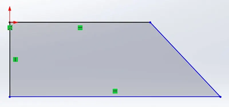
The green symbols shown above represents some of the above explained sketch relations. These are captured during the sketching process and can reveal these symbols by left- click on a line segment. Additionally, the blue colors of the lines indicate that these segments are not fully defined, meaning they are still free to move. It is best practice to fully define sketches (with a few exceptions), although it is possible to create features from sketches that are under defined.
- Appearances
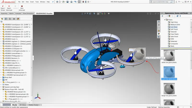
An appearance defines the visual properties of a model, including color and texture. Appearances do not affect physical properties, which are defined by materials. Every material is assigned a default appearance that emulates the look of the material.
- Render tools
- Edit appearance: edit the appearance of entities in the model
- Copy appearance: copy the appearance of entities in the model
- Paste appearance: paste the appearance to entities in the model
- Edit scene: edit the scene applied to the document
- Edit decal: applies decals to the faces in a model.
- Preview window: opens the photoview 360 preview window which is a real-time rendering process of how the model look after final rendering
- Final rendering: it invokes a photoview 360 final rendering which is the high-quality rendering.
- Options: it is a setting option which promotes editing the photoview 360 rendering.
- Assembly tools
- Edit component: toggles between editing a part or a subassembly and the main assembly
- Inset component: adds an existing part or subassembly to the assembly.
- Linear component pattern: pattern components in one or two linear directions.
- Circular component pattern: pattern components in radial directions
- Mate: create geometric relationships between assembly components by positioning components relative to one another.
- Exploded view: separates the components into an exploded view.
DESCRIPTION:
In SolidWorks the very first step for modeling any component is to begin with selection of plane in which the sketch profile is drawn as per the required design approach followed by feature tools such as extrude boss to convert any 2d sketch to solid body. Using similar operation different parts of the chopper are as followed: -
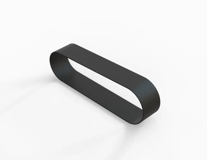
- Modeling of transmission belt
A transmission belt is a loop of flexible material used to link two or more rotating shafts. It can transmit power or motion without losing synchronization. It transfers continuous rotational motion between a drive shaft and a driven shaft separated by a fixed distance. These belts are made mostly of Rubber canvas material having upsides such as low slip, long life and low maintenance costs. The only downside of belt is power lost during transmission.
Tools used in modeling:
Sketch tools:
- 3 Point arc
- Line
- Sketch offset
Feature tools:
- Extrude
- Fillet
Render tool:
- Edit Appearance
Design procedure:
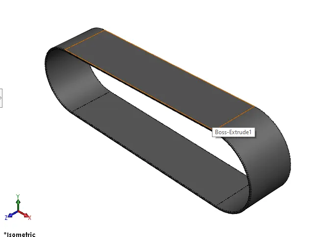
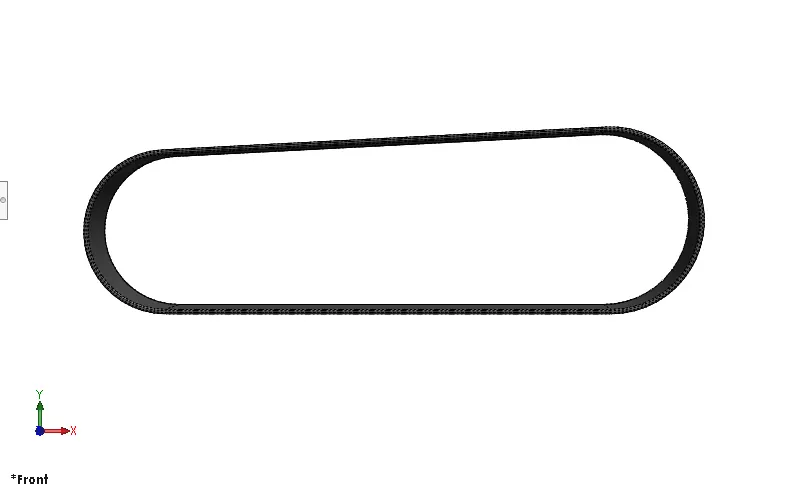
- The design of the transmission belt begins with a sketch on front plane, where we draw a horizontal line from origin of 350mm followed by an arc of 70mm radius.
- From the end point of the 70mm radius arc another line is drawn slightly towards origin by giving an equal relation to the horizontal line. There by closing the loop with another arc of radius 61mm.
{Note: all the arc must be in tangent relationship with the line their end points are connected to.}
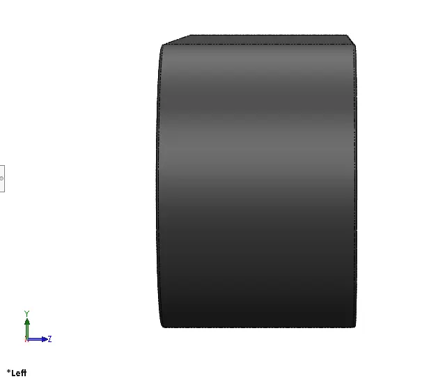
- After the loop is fully defined an offset of 3.5mm is given and then the complete sketch is extruded up to 88mm.
- Finally, appearance of Matte Rubber is applied on the part and the part file is saved with desired file name.
Different views of the model:
- Modeling of Kickstand
A kickstand is a machine component on a bicycle or motorcycle that allows the bike to be kept upright without leaning against another object or the aid of a person. The kickstand is mounted to the chassis through a mounting point. It is usually a piece of metal that flips down from the frame and makes contact with the ground. The design and selection of material should be done in way that it provides high tensile/compressive strength to withstand the load of bike.
Tools used in modeling:
Sketch tools:
- Ellipse
- Spline
- Pierce
Feature tools:
- Loft
- Split
- Dome
- Extruded Boss
- Extruded Cut
- Fillet
Render tools:
- Edit appearance
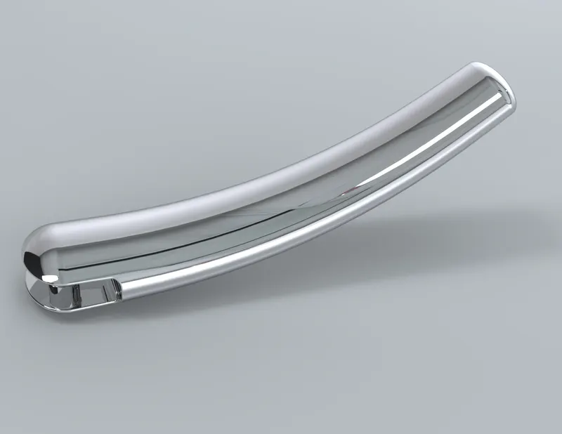
Design procedure:
- Start from drawing an ellipse on the front plane taking origin as center of 40 mm width and 18mm height and applying horizontal relationship to the end point of the major axis of ellipse.
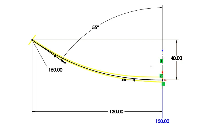
- After that a spline is drawn from the centre of the ellipse on the right plane (in this case renamed as midplane) with appropriate weights, dimensions and relations as shown below.
- Create a reference plane (i.e., plane 1) perpendicular to the other end of spline and sketch an ellipse of width 30mm and height of 12mm, giving a pierce relation to the ellipse and the spline
- Use Loft feature more specifically the Centre line loft by selecting the spline as the Centre line and the 2 ellipses as references.
- Now create dome of 13mm on the larger elliptical end of the solid body created and a dome of 5mm on another elliptical end.
- Sketch a centre point rectangle on the right plane from the origin of width 28mm and height 8mm.
- Extrude cut the sketch using through all- both, creating a cut-out for stand mount.
- Sketch a circle of 9mm diameter on the cut section face and extrude boss the same up to next to create a stand mount.
- Sketch a straight line of 50mm, 4.5mm below the origin.
- Use split feature with consume-cut body option turned on, creating a flat bottom for the kickstand to rest on.
- Save the part file after applying the fillets of 2mm and 0.5mm and chromium plate appearance to the part.
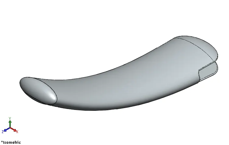
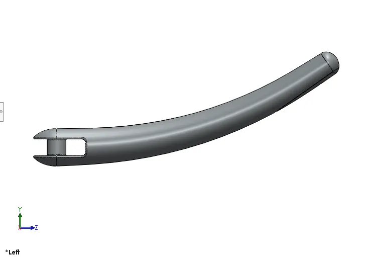
Different views of the model:

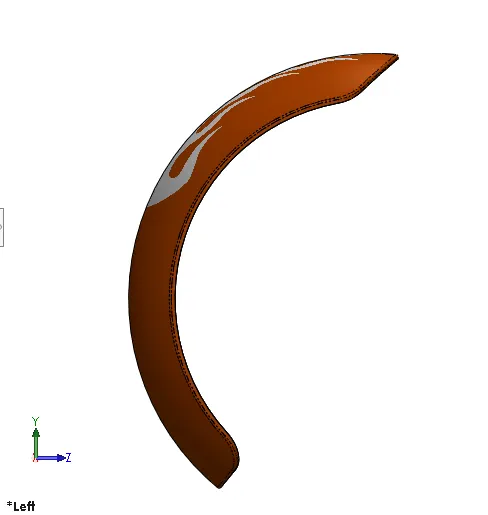
- Modeling of fender
A fender is a part of an automobile, motorcycle or other vehicle body and is placed as a cover on the upper side of the tires in case of motorcycles. Its primary purpose is to prevent sand, mud, rocks, liquids, and other road spray from being thrown into the air by the rotating tire. Fenders are typically rigid and can be damaged by contact with the road surface. Front wheels require the fenders to provide mud and gravel protection on the rear side i.e., the rider side and the engine.
- Modeling of front fender
Tools used in modeling:
Sketch tools:
- 3-Point arc
- Sketch offset
- Line
- Spline
Features:
- Revolve
- Split
- Dynamic mirror entity
- Fillet
Render tools:
- Edit Appearance
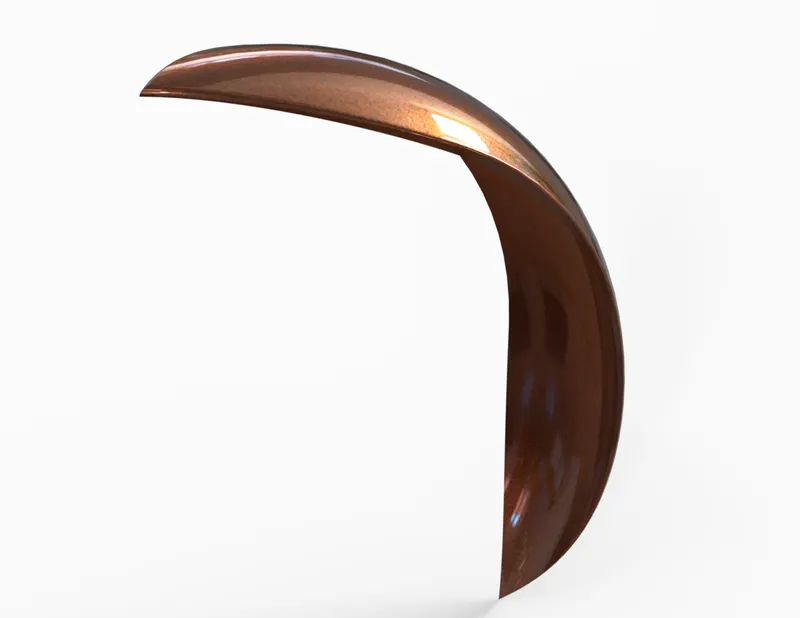
Design procedure:
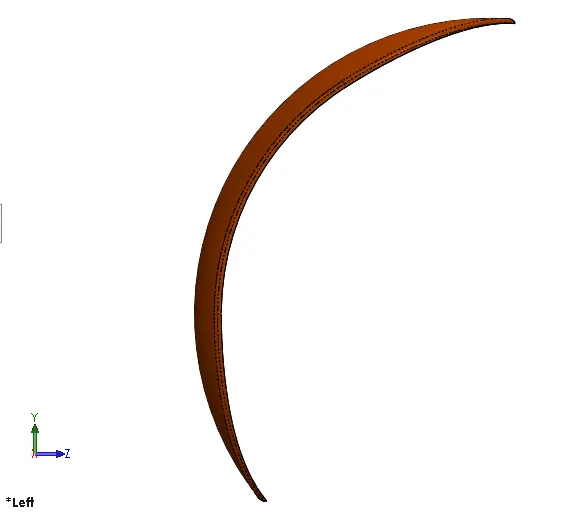
- Designing of front fender begin with renaming the Front, Top and Right plane as vertical plane front fender, Centre plane Front fender and midplane front fender.
- Sketch 3-point arc of radius 125mm and end point distance 160mm on the vertical plane front fender, making the end points of arcs horizontal.
- Vertical relation is applied to the centre of arc to origin followed by a separation distance of 280mm from the origin.
- An Offset of 6mm inwards is applied to the 3-point arc and sketch a horizontal construction line from the origin for creating a revolved body.
- Revolve the closed sketch about the origin line with direction1 = 5° and direction2 = 130°.
- On centre plane front fender sketch a centre construction line on the fender face and apply dynamic mirror entity for line.
- Now sketch a spline of appropriate dimensions (as shown in the image) on one side of the centre line of the fender face.
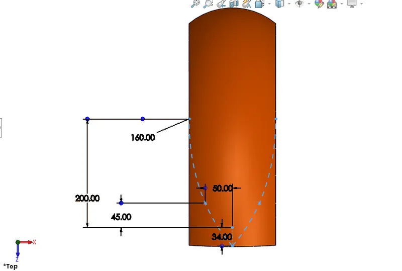
- Use split feature to cut parts and consume body to give a aesthetic cut on the top of fender, similar operation is followed on the other end of fender on the vertical plane front fender.
- Finally fillet of 6mm is applied to the sharp edges followed by applying Siena painted metallic car appearance on the part.
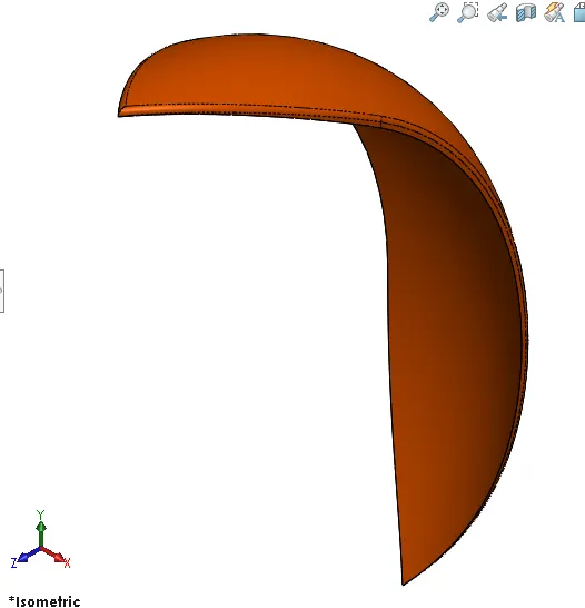
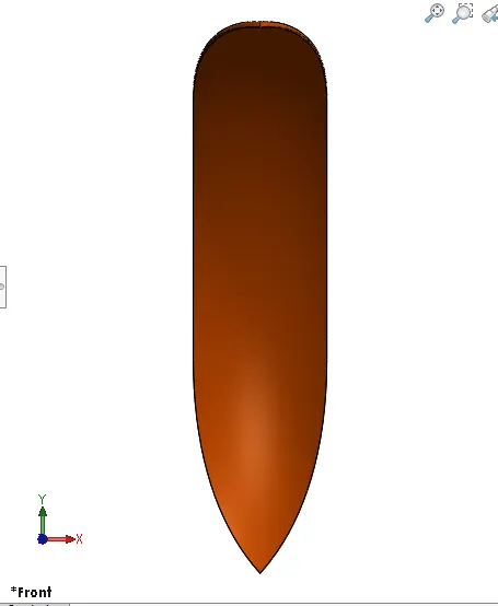
Different views of the model:
- Modeling of Rare fender
Tools Used:
Sketch tools:
- 3-Point arc
- Sketch offset
- Line
- Spline
Feature tools:
- Revolve
- Split
- Shell
- Dynamic mirror entity
- Fillet
Render tools:
- Edit appearance
Design procedure:
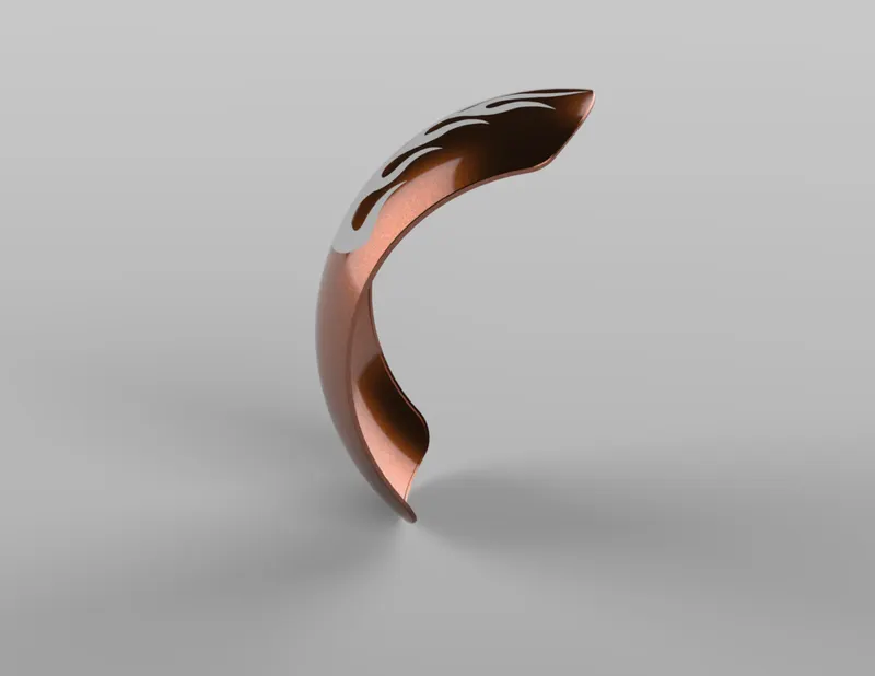
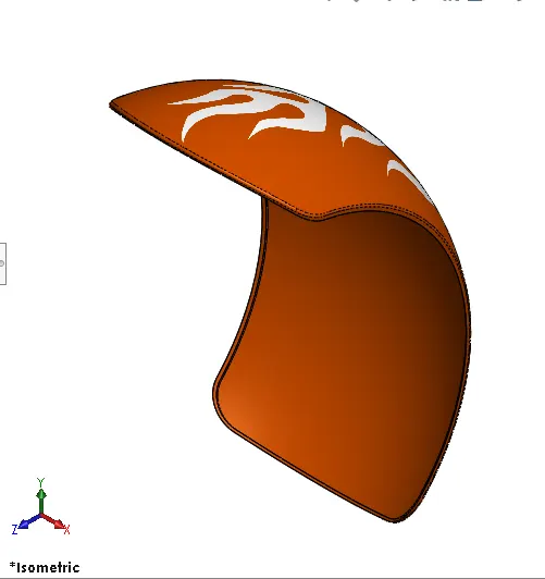
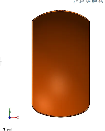
- Designing of rare fender begin with renaming the Front, Top and Right plane as vertical plane rare fender, Centre plane rare fender and midplane rare fender.
- Sketch 3-point arc of radius 290mm and end point distance 364mm on the vertical plane front fender, making the end points of arcs horizontal.
- Vertical relation is applied to the centre of arc to origin followed by a separation distance of 90mm from the origin.
- An Offset of 6mm inwards is applied to the 3-point arc and sketch a horizontal construction line from the origin for creating a revolved body.
- Revolve the closed sketch about the origin line with direction1 =10° and direction2 = 141°.
- On centre plane front fender sketch a 3-point arc of radius 265mm with separation distance of 227mm between the centre of arc and the origin.
- Use split feature to cut parts and consume body to give an aesthetic cut on the top face of fender and applying fillet of 45mm on all 4 corners of the fender.
- Now use the shell feature with 4mm on inside face of the fender
- Finally applying Siena painted metallic car appearance to whole body and saving the file.
Different views of the model:
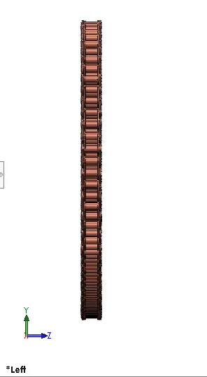
- Modeling of Transmission Chain
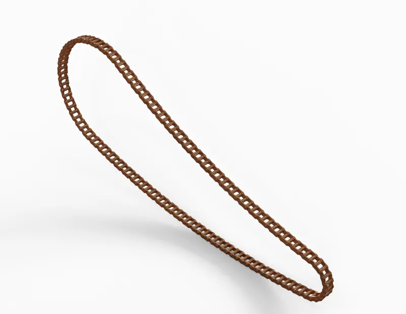
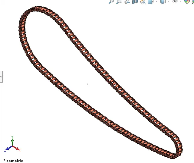
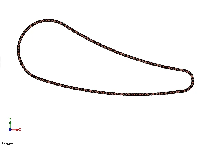
The motorcycle chain is the most common type of final drive. More specifically, it’s known as the “roller chain.” This a set of several links made of small plates and pin joints, connected in a loop to make a power transmission component. These pins are covered by cylindrical “rollers” that allow smoother running over sprockets. The main advantage of chain is high power transmission capacity, good flexibility, low cost.
Tools Used:
Sketch tools:
- 3-Point arc
- Centrepoint slots
- Circle
- Trim
Feature tools:
- Extruded boss
- Make and save block
- Fillet
- Curve driven pattern- tangent to curve
- Mirror
Render tools:
- Edit appearance
Design procedure:
- Designing of chain begin with renaming the Front, Top and Right plane as Mid Plane chain, Centre Plane chain and Front plane chain.
- Continue with mid plane, by sketching a horizontal construction line from the origin of 650mm and a vertically downward construction line from the end point of the horizontal line of 147mm.
- Draw two circle one at start of horizontal construction line of 289mm dia and other at end of vertically construction line of 99mm dia.
- Sketch two 3-point arcs of 1500mm connecting both the circle at top and bottom without snaping to the points visible on circle.
- Trim the sketch according to the need and provide tangent relation to both the arc with the circle.
- Create 2 chain links with pins of diameter 8mm and centre to centre distance of 15.13mm.
- Create blocks for the links created and save for future use.
- Now again continue on the midplane and import the blocks.
- Arrange the two blocks along the chain path and extrude the pins and plates one by one.
- Providing the fillet of 0.5mm two the pins and using the linear pattern and circular pattern tool as per requirement.
{Note: put all the pins and plates in different folder for easy access in the feature tree.}
- Now use the mirror entities to mirror the plates to other end of pins.
- Finally applying polished copper appearance, the part and saving the file with desired name.
Different views of the model:
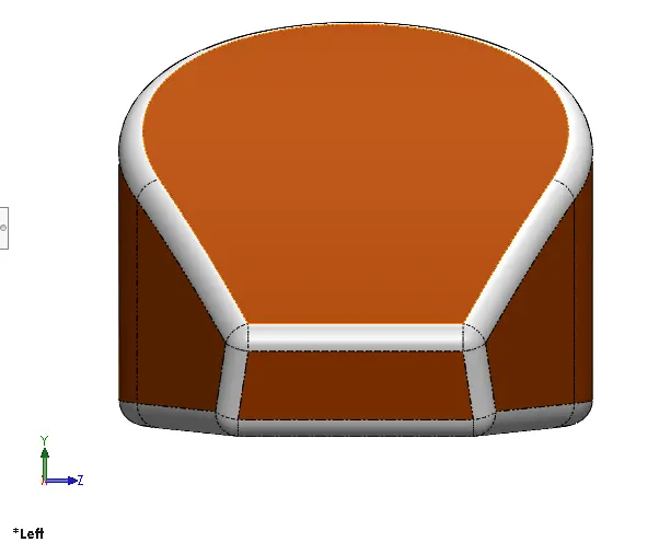
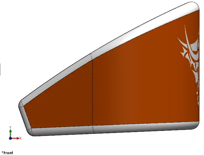
- Modeling of Oil Tank
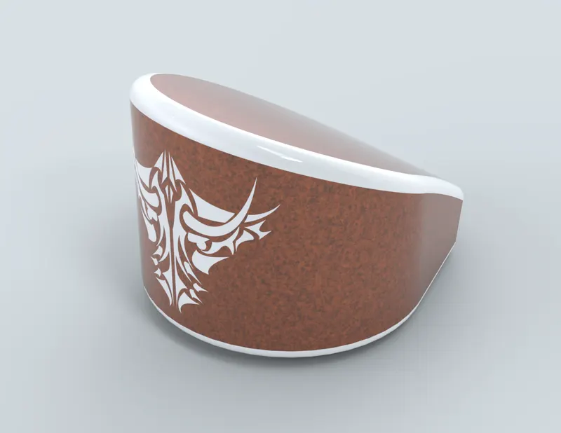
Oil tank is a component used to store the oil for lubrication and cooling purposes of engine components. Oil tank is required in the chopper as it uses a dry-sump engine and dry sump engines have an external oil tank because the oil has to be held somewhere. This tank is placed right below the rider seat on top of the gearbox.
Tools Used:
Sketch tools:
- 3-Point arc
- Line
- Dynamic mirror entities
Feature tools:
- Extruded boss/base
- Fillet
- Combine
- Shell
Render tools:
- Edit appearance
Design procedure:
- Designing of chain begin with renaming the Front plane to mid plane oil tank.
- Begin sketching the base of the oil tank on top plane by drawing a construction line of 230mm to the left of origin.
- draw a vertical line of 50mm from the end of construction line followed by a line at any angle above the end point of vertical line with dynamic mirror entities active.
- Draw an arc up to the origin and a point vertically up from origin at 146mm.
- Make the line at any angle coincide the point and extruding the sketch up to 170mm.
- Begin with midplane and sketch as shown in the image below.
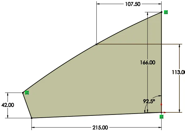
- Extrude this sketch through all in both directions followed by Combine feature and select operation type as common.
- Fillet all the edges 10mm and create a shell of 3mm to create a hollow tank.
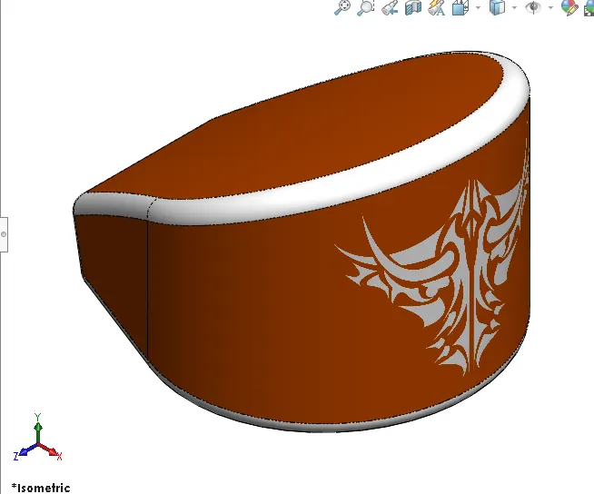
- Finally apply Siena appearance to the tank and white appearance to fillets.
Different views of the model:
- Modeling of pedal
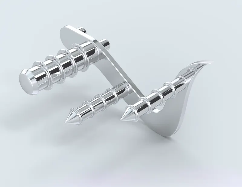
A pedal is a motorcycle component used by the rider to place his/her foot on it while riding the bike. Its position depends on the type of motorcycle. In a chopper type motorcycle, the pedals are placed in forward position such that the legs of the rider are fully extended in a comfortable manner. The pedals also contain protruded sections so as to provide grip to the rider’s foot to avoid any kind of slippage.
Tools Used:
Sketch tools:
- 3-Point arc
- Circle
- Spline
- Line
- Sketch fillet
Feature tools:
- Extruded boss
- Revolve
- Fillet
- Dome
- Chamfer
- Linear pattern
Render tools:
- Edit appearance
Design procedure:
- The design begins with front plane as shown below.
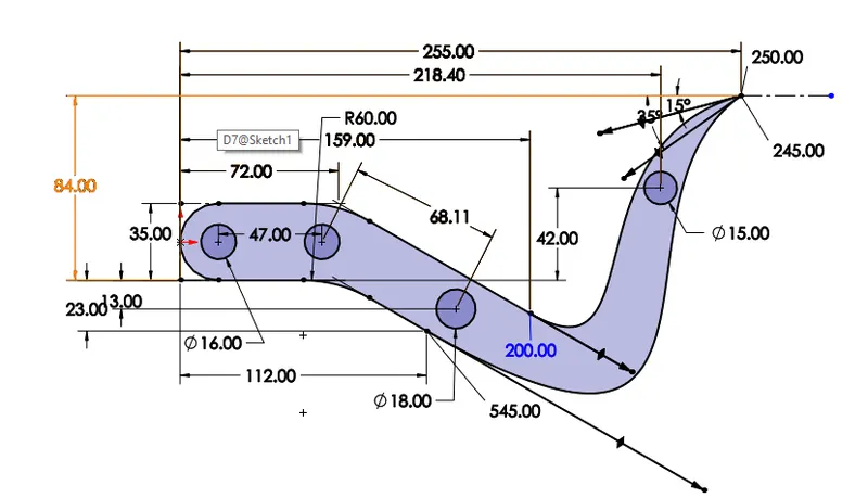
- Use Extrude operation on the sketch according followed by fillet of 1mm on the faces.
- Sketch on top plane and perform revolve operation followed by dome of 3mm and fillet of 1mm.
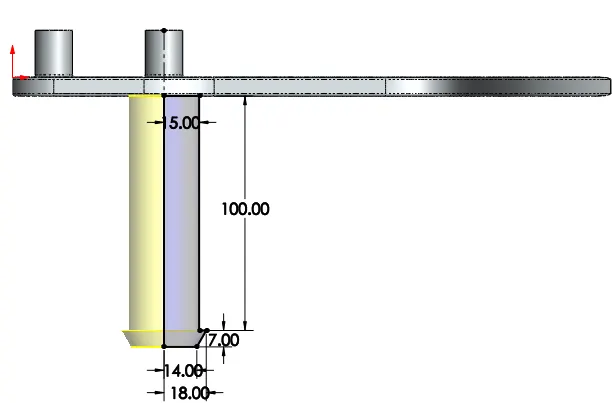
- Use chamfer of other to cylindrical extrudes on 18mm and 15mm dia circles.
- Offset the circles of the face of pedal and extrude them as per requirement followed by linear pattern and application of chromium appearance.
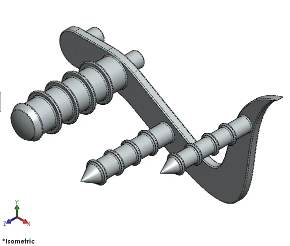
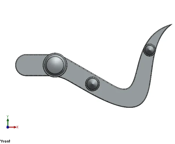
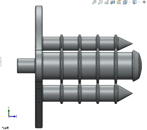
Different views of the model:
- Modeling of Wheel
The wheels are made to cope with radial and axial forces. Wheel consists of the rims and the tire which make it the component that makes connection between the motorcycle and the ground. The tires are the main contact surface to the ground. It is generally made up of rubber to ensure flexibility and bump absorption. The tires contain treads which provides grip to the road. The wheel also houses a Disc brake rotor and its caliper.
Front wheel
Front wheels of choppers are always larger than the rear wheel with narrow section as compared to the rare wheel.
Tools Used:
Sketch tools:
- 3-Point arc
- Lines
- Splines
- Mid-point line
- Circle
- Sketch fillet
- Trim
- Extend
- 3-point centre rectangles
Feature tools:
- Revolve boss/base
- Extrude boss/base
- Extrude cut
- Revolve Cut
- Circular Pattern
- Combine
- Fillet
- Chamfer
Render tools:
- Edit appearance
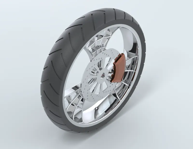
Design procedure:
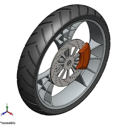
- Design begins with a sketch on the front plane which is revolved for making the rim and the rotor.
- On right plane sketch the shape of a spoke and extrude it midplane- 122mm.
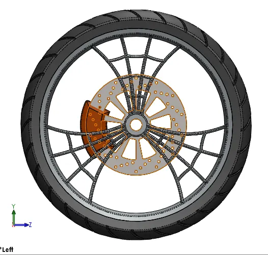
- On the face of the spoke sketch the spider web design followed by extrude cut.
- Again, begin a sketch on the top plane using line, arcs and mirror entity, which is followed by revolve cut, giving the desired shape to the spokes of the rim.
- use of circular pattern is done to obtain the required no. of spokes.
- Use the combine tool to make all the spokes and the rim as one single body, followed by the fillets.
- On the right plane a sketch for disc is drawn and is extruded by offset of 45mm.
- Sketching on face of disc is done to create ventilation holes and ventilation slots which are extrude cut and are followed by circular pattern to obtain the desired ventilation holes and slots.
- Sketch a circle on right plane followed by extrude cut to obtain similar hole as in the rotor for the axle.
- On the face of centre disc sketch a caliper and extrude it, followed by chamfers on the faces and fillets on the edges and corner.
- On the front plane sketch for tire above the rim and revolve the sketch about any temporary axis.
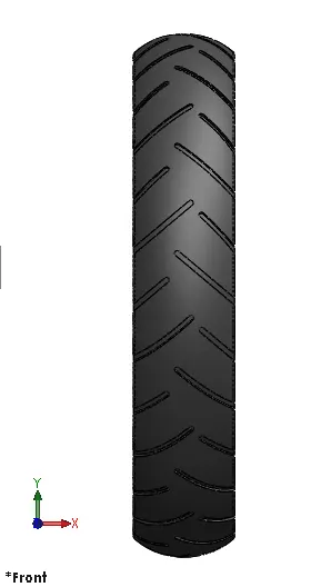
- Again, on the front plane sketch the thread and extrude cut them by offsetting 450mm and 4mm direction one on the tire face followed by fillets and then using circular pattern to obtain threads all over the tire.
- Finally applying Siena car paint appearance to caliper, chromium plate to disc brake, rims and spokes and matte rubber appearance to tire and saving the file.
Different views of model:
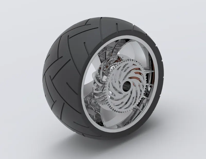
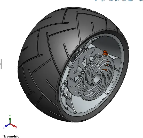
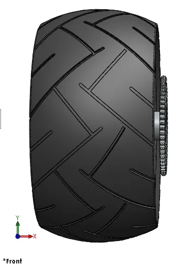
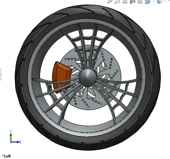
- Rear wheel
Rear wheels of choppers are generally smaller in diameter than the front wheel having a broad section as compared to the latter. The tires have a broad section meaning broader surface contact, heavy load carrying capacity and greater grip.
Tools Used:
Sketch tools:
- 3-Point arc
- Lines
- Splines
- Mid-point line
- Circle
- Sketch fillet
- Trim
- Extend
- 3-point centre rectangles
Feature tools:
- Revolve boss/base
- Extrude boss/base
- Extrude cut
- Revolve Cut
- Circular Pattern
- Combine
- Fillet
- Chamfer
Render tools:
- Edit Appearance
Design procedure:
- Design begins with a sketch on the front plane which is revolved for making the rim and the rotor.
- On right plane sketch the shape of a spoke and extrude it midplane- 300mm.
- On the face of the spoke sketch the spider web design followed by extrude cut.
- Again, begin a sketch on the top plane using line, arcs and mirror entity, which is followed by revolve cut, giving the desired shape to the spokes of the rim.
- use of circular pattern is done to obtain the required no. of spokes.
- Use the combine tool to make all the spokes and the rim as one single body, followed by the fillets.
- Sketch a circle of 60mm dia on right plane at center followed by extrude cut-through all-both, in both directions to obtain hole for axle.
- Sketch an axle on the front plane about the rotor and use revolve boss for the sketch.
- On the right plane a sketch for disc brake is drawn and is extruded by offset of 105mm and 7mm direction1.
- Sketching on face of disc brake is done to create ventilation holes and ventilation slots which are extrude cut and are followed by circular pattern to obtain the desired ventilation holes and slots.
- On the face of centre disc, sketch a caliper and extrude it, followed by chamfers on the faces and fillets on the edges and corner.
- Sketch a circle of 300mm dia on rare face of axle and extrude it forming a sprocket which is followed by chamfer operation.
- For the teeth of the sprocket sketch on sprocket face and extrude cut the sprocket, followed by circular pattern feature.
- Sketch of sprocket cuts are drawn on sprocket face and are extrude cut followed by fillets and then by circular pattern feature.
- On the front plane sketch for tire above the rim and revolve the sketch about any temporary axis.
- Again, on the front plane sketch the thread and extrude cut them by offsetting 400mm and 6mm direction1 offset from surface on the tire face followed by fillets and then using circular pattern to obtain threads all over the tire.
- Finally applying Siena car paint appearance to caliper, chromium plate to disc brake, rims and spokes and matte rubber appearance to tire and saving the file.
Different views of model:
- Modeling of Front fork
A motorcycle fork connects a motorcycle's front wheel and axle to its frame. Most forks incorporate the front suspension and front brake, and allow the front wheel to rotate about the steering axis so that the bike may be steered. It consists of front suspension component which is generally called telescopic forks. Itis a 2-piece unit with hollow tube consisting of suspension oil and another piece a solid one which compresses the oil while tackling a bump or rough road surface.
Tools Used:
Sketch tools:
- 3-Point arc
- Lines
- Splines
- Circle
- Trim
Feature tools:
- Revolve boss/base
- Extrude boss/base
- Linear Pattern
- Extrude cut
- Revolve cut
- Dome
- Body move/copy
- Curves-Projected
- Sweep
- Reference geometry- planes
- Mirror
- Combine
- Fillet
- Chamfer
Render tool:
- Edit appearance
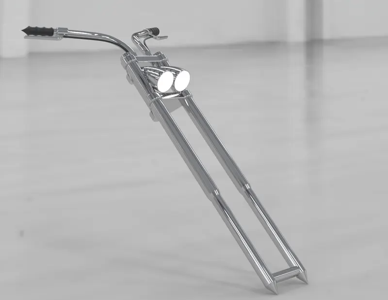
Design procedure:
- The design begins with a sketch on front plane which is revolved around.
- On the circular rod so formed, sketch of triple clamp of fork is sketched and is extruded 20 mm below the sketch.
- Fillet is applied to the clap and a linear pattern is used to obtain lower triple clamp.
- From the conical end of the rod at 70mm a circle of 40mm dia is drown and extruded.
- Then On the upper face of the lower clamp a semicircle of 50mm dia is sketched an extruded up to lower surface of the upper clamp.
- On the front plane sketch for headlight bucket is drawn and revolved, followed by extrude cut of 5mm of headlight detailing sketch on the face for headlight.
- dome of 7mm is created on the face of headlight for headlight lens.
- At the top plane and at front plane curves are drawn to obtain a project curve to sweep a circle along it.
- At the end of sweep create a reference plane perpendicular to the end circle and passing through its centre.
- Sketch the handle grip sketch on the reference plane and use revolve feature.
- taking 1st reference plane as reference another plane is created at 160 from the plane1.
- From this plane2 brake lever is sketched and extruded, followed by fillet.
- At top plane and right plane curves are drawn to obtain projected curve to sweep circle through it and make brake cable.
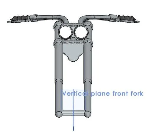
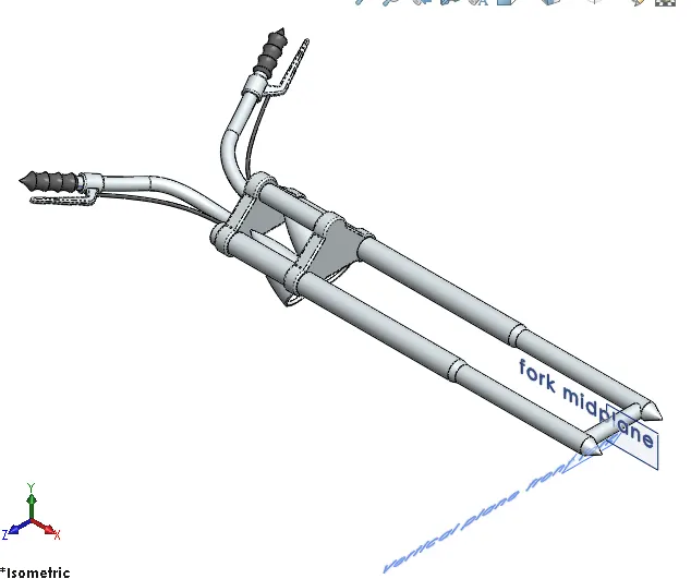
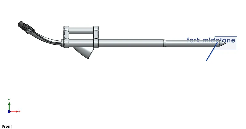
- Finally mirror and combine feature are used to complete the fork, followed by setting up of appearance: - chrome for headlight bucket, triple clamp and the handle bar, glossy rubber for the handle grip, cables and white area lights to headlight face.
Different views of the model:
- Modeling of Chassis
Chassis is the main support structure of the vehicle which is also known as ‘Frame’. It bears all the stresses on the vehicle in both static and dynamic conditions therefore it should be made up of high strength material. In a vehicle, it is analogous to the skeleton in living organisms. All components of the motorcycle are either directly or indirectly mounted to the chassis.
Tools Used:
Sketch tools:
- Sketch Picture
- Lines
- Splines
- Circle
- Trim
Feature tools:
- Extrude boss/base
- Extrude cut
- Revolve
- Dome
- Curves-Projected
- Sweep
- Split
- Reference geometry- planes
- Mirror
- Combine
- Fillet
- Chamfer
Render tools:
- Edit Appearance
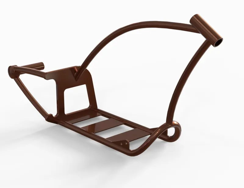
Design procedure: -
- The top, front planes are renamed to bottom plane chassis and midplane chassis.
- On midplane sketching is done to import picture of the chopper as a reference for designing the chassis and its position is defined by defining the x and y coordinate.
- Sketch on midplane and bottom plane are made to obtain desired projected curve similarly another projected curve is obtained from the sketch on right plane and midplane.
- A concentric circle is drawn at the end of the projected curve and swept, followed mirror feature.
- At the right plane sketch for back plate is drawn and extruded followed by chamfer and fillet feature.
- From the midpoint plane a plane is made parallel to it by using vertices as reference.
- From the back face of the back plate two hollow tubes are made by sweep feature.
- On the plane a sketch of hub is made and extruded to form a hub for the axle.
- At the midplane a plane spline as sketched, followed by defining plane2 perpendicular to the end point.
- On plane circle is sketched and swept through the curve and use split feature to obtain the required tube only.
- Then steering stem is sketched on the midplane and revolved to obtain a solid body.
- After that base plates and foot peg mount are sketched, followed by kickstand mount sketch.
- Finally, Siena appearance is applied to the component and saved.
Different views of model:
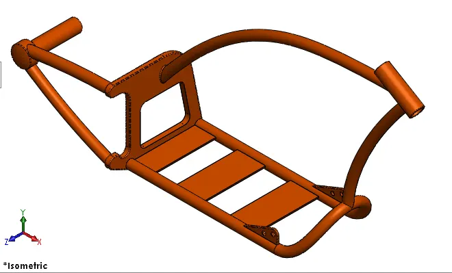
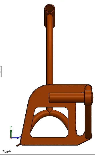
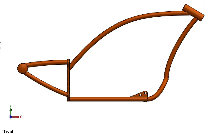
- Modeling of Engine
An engine or motor is a machine designed to convert one form of energy into mechanical energy. The engine used in this motorcycle is a V-twin engine consisting of external air filter, spark plug for each cylinder, transmission pulleys, air cooling fins, starter motor, front sprocket for chain drive, exhaust pipes and casing for sump and gearbox. V-twin engines have also been used for industrial engines and in several small cars.
Tools Used:
Sketch tools:
- Sketch Picture
- Lines
- Splines
- Circle
- Circular sketch pattern
- Construction line
- Centre point rectangle
- 3-point centre rectangle
- Trim
Feature Tools:
- Extrude boss/base
- Extrude cut
- Revolve
- Dome
- Curves-Projected
- Composite curves
- Sweep
- Split
- Reference geometry- planes
- Circular pattern
- Linear Pattern
- Mirror
- Combine
- Fillet
- Chamfer
Render tool:
- Edit Appearance
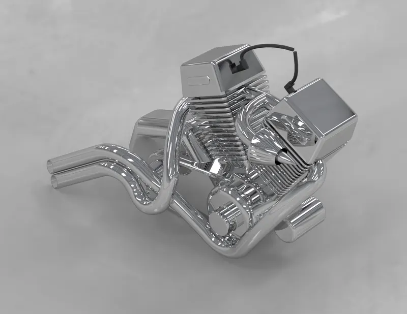
Design procedure:
- Design begins with importing the reference chopper image in the sketch environment on front plane.
- using the picture reference, sketch the base of engine on front plane and extrude-midplane the base and the gearbox.
- On right plane, Sketch for transmission belt pulleys and revolve the sketch and make extruded rectangles on the pulley for grip element for belt and use circular pattern feature followed by Making circular pattern holes on pulley face and apply dome for better appearance.
- Similar operation is followed on the rear pulley.
- A reference plane is created by sketching a line in reference of the image, followed by Sketching a rectangle on the plane and extrude it as per sketch reference.
- Fins are made using linear pattern and fillet as required.
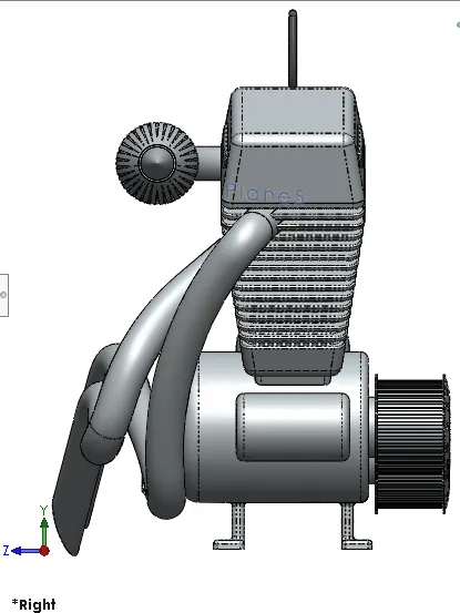
- Followed by spark plugs and which is Mirrored across the right plane to create second cylinder casing.
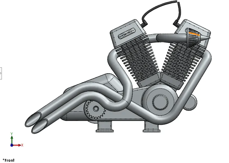
- Mounts are created on bottom for the chassis mounts and then front sprocket was sketched followed by extrude, chamfer and chain cuts as done on rear sprocket on the rare wheel followed by chamfer to the sprocket shaft
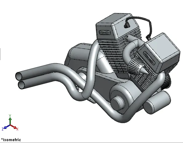
- Then using splines, projected curves are obtained for exhausts pipes and air intake manifolds.
- Using sweep feature and split feature exhaust pipes and air intake manifolds are made.
- Also using sweep feature the spark plug cables are made.
- Finally, chromium appearance to the engine and gloss black to spark plugs and the cables is applied and saved.
Different views of the model:
- Modeling of Gas Tank
A fuel tank (also called a petrol tank or gas tank) is a storage tank in which flammable fuel is stored. The gas tank can be made out of plastic high-density polyethylene, which can be made into complex shapes, save space, and can improve crash safety. The gas tank can also be made out of steel or aluminum, which is welded from stamped sheets. The material that makes up the gas tank depends on the make and model of the vehicle.
Tools Used:
Sketch tools:
- Sketch Picture
- Lines
- Splines
- Construction line
- Trim
surface tools:
- Surface sweep
- Surface loft
- Surface trim
- Boundary Surface
- Surface knit
- Surface Extrude
- Curves
- Projected curves
- Split line
- Sweep cut
- Reference geometry- planes
- Mirror
- Shell
- Fillet
Render tools:
- Edit Appearance
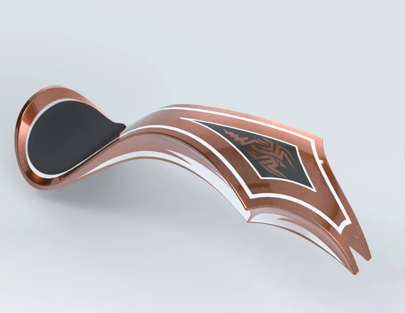
Design procedure:
- The design begins with Front, Top and Right planes to Midplane fuel tank, bottom fuel tank and right fuel tank.
- At midplane sketch picture is brought in sketch environment for reference.
- With the help of reference picture spline is sketched on the midplane sketching the top profile of gas tank.
- Using swept surface, the sketch in swept in the required direction and from sketching on bottom plane, surface trimming is done obtaining the desire shape of the top of gas tank.
- New planes are created for obtaining the projected making the sides of the gas tank by use of surface loft, boundary surfaces like surface tools.
- Now performing the mirror and knitting operation the top and side of tank are created.
- At the bottom plane sketch for seat is sketch and by using split line feature sketch is on the top face of the gas tank which followed by extrude and fillet operation.
- The lower face of the gas tank is created by the use of boundary surface and surface loft tool followed by fillet operation.
- At the head of the gas tank a profile is extrude-cut so the gas tank could rest on the upper tube of chassis and create shell using shell.
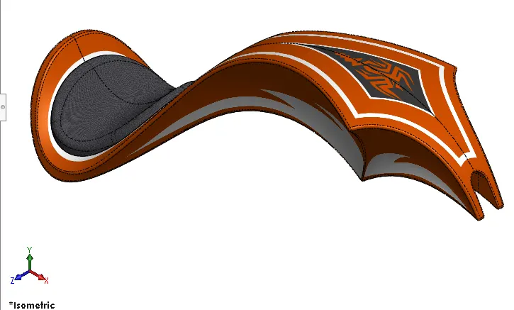
- Finally, Siena appearance is given to the gas tank and grey cotton appearance to the seat followed by saving the file.
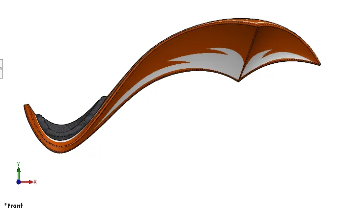
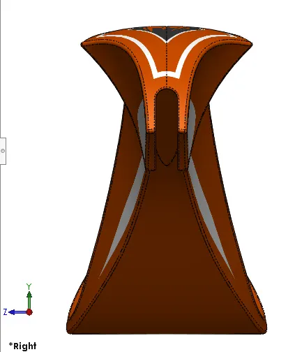
Different views of the model:
- Assembly of American chopper
After all, the components of the American Chopper are designed in the part design environment, assembly is then created form the part files. In SOLIDWORKS, the feature which connects or joins two different components is called mate. The parts are imported into the Assembly environment and then required mates are applied to each individual part with respect to the connecting part. The first part inserted into the assembly is always fixed by default.
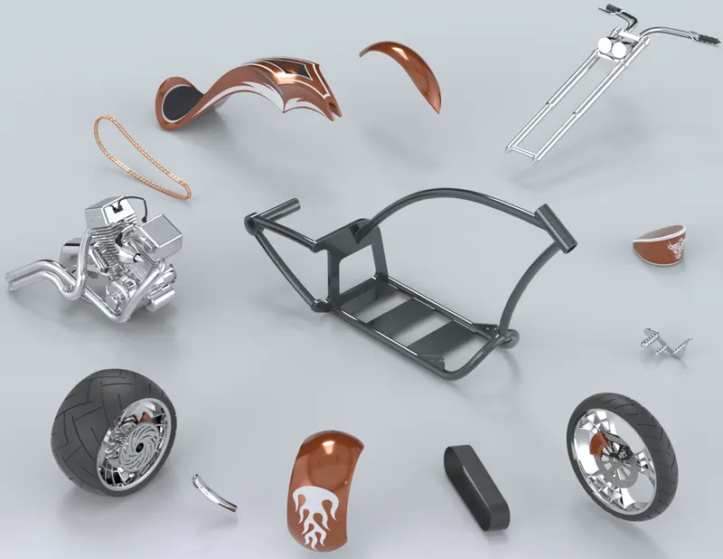
The first part imported in the assembly is chassis which Is by default fix and then engine is imported to the assembly environment and mates are applied between chassis and engine to place the engine in the required place. Similarly other parts like oil tank, front fork, wheels, fender, gas tank, chain and belt are imported to the assembly environment and mated accordingly.
{Note: all plane of components must mate with plane of chassis not with the plane of assembly environment}
The parts in assembly environment are also edited and modified when then interfere with other components. In this case the exhaust pipe, kickstand and chassis were modified on the basis of need.
Different views of the assembly
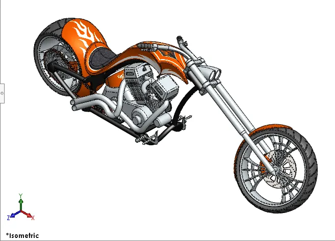
ISOMETRIC VIEW
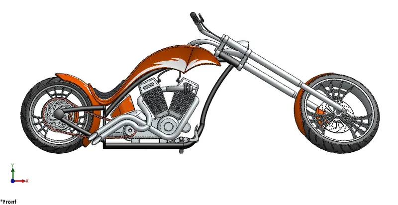
FRONT VIEW
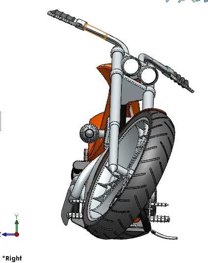
SIDE VIEW
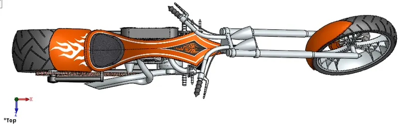
TOP VIEW
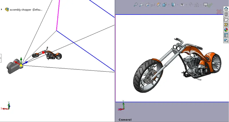
CAMERA SET-UP VIEW
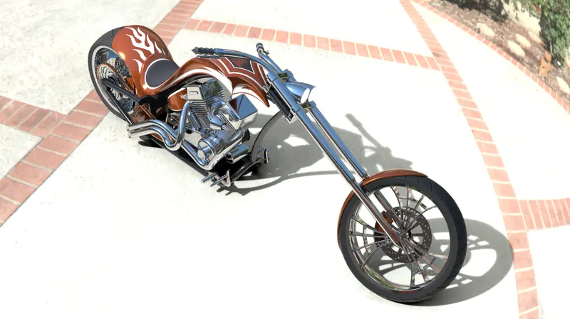
- Render of the American chopper
Rendering is done by designer to obtain a photo-realistic image out of the 3d model created on any CAD software. This helps the designer have a better understanding of his design will look in real world. For proper rendering, there is a need to set up the correct scene, light, camera views and decals if necessary.
In SolidWorks rendering can be done by two mediums:
- Photo View 360 which is one of the add-ons of SolidWorks
- ‘SOLIDWORKS Visualize’ is another powerful tool of SOLIDWORKS which comes as separate software
SolidWorks visualize produces high quality renders compared to photo view 360.
Rendering Process:
The rendering process includes the following steps:
- Apply scene
- Apply lights
- Apply decals
- Adjust camera view
- Adjust image quality
- Render
After the rendering is complete, the rendered images are used for presentation purposes.
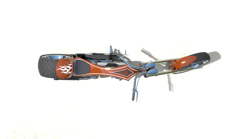
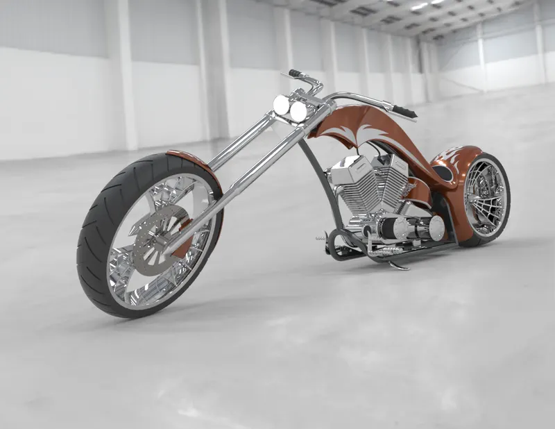
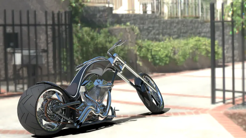
Different rendered views of chopper in different environment
ISOMETRIC VIEW
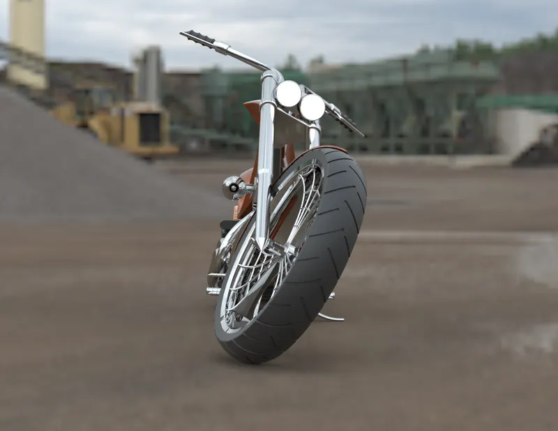
FRONT VIEW
SIDE VIEW
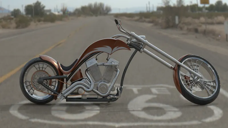
TOP VIEW
CAMERA SET-UP VIEWS
- conclusion:
The design, assembly, and rendering of an American Chopper is done using SOLIDWORKS. The project has enhanced my designing skills during whole journey of making of the American chopper. Through this project one can learn how to approach a design in an effective manner and end up with an industry ready product design. All over the project was successful.