Radar Mast & Final Assembly of Yacht
3D-Modeling and Photo-realistic Rendering of the Sunseeker Predator 108 Yacht using SolidWorks
Introduction:
SolidWorks is a solid modelling computer-aided design (CAD) and computer-aided engineering (CAE) computer program published by Dassault Systems. It has the most efficient and powerful CAD design collection available for product and part assembly designers.
SolidWorks is a solid modeller and utilizes a parametric feature-based approach to create 3d models. Parameters refer to constraints whose values determine the shape or geometry of the model or assembly. Parameters can be either numeric parameters, such as line lengths or circle diameters, or geometric parameters, such as tangent, parallel, concentric, horizontal or vertical, etc. Numeric parameters can be associated with each other through the use of relations, which allows them to capture design intent.
Building a model in SolidWorks usually starts with a 2D sketch. The sketch consists of geometry such as points, lines, arcs, conics, and splines. Dimensions are added to the sketch to define the size and location of the geometry. Relations are used to define attributes such as tangency, parallelism, perpendicularity, and concentricity. The parametric nature of SolidWorks means that the dimensions and relations drive the geometry, not the other way around. The dimensions in the sketch can be controlled independently, or by relationships to other parameters inside or outside the sketch.
In an assembly, the analogy to sketch relations is mates. Just as sketch relations define conditions such as tangency, parallelism, and concentricity with respect to sketch geometry, assembly mates define equivalent relations with respect to the individual parts or components, allowing the easy construction of assemblies.
Drawings can be created either from parts or assemblies. Views are automatically generated from the solid model, and notes, dimensions and tolerances can then be easily added to the drawing as needed.
Objectives:
The main objective of this project is to create a 3D-Model of the Sunseeker Predator 108 Yacht and create a Photo-realistic rendering of the created model.
The modelling part can be divided into two parts as follows:
- Creating individual parts using SolidWorks.
- Assembling all the individual parts to create the complete model.
The Rendering the model can be divided into three parts as follows:
- Applying the appropriate materials and decals into the model.
- Setting up the Positions, Cameras, Environment and Lights.
- Rendering high-quality images of the model using any rendering software.
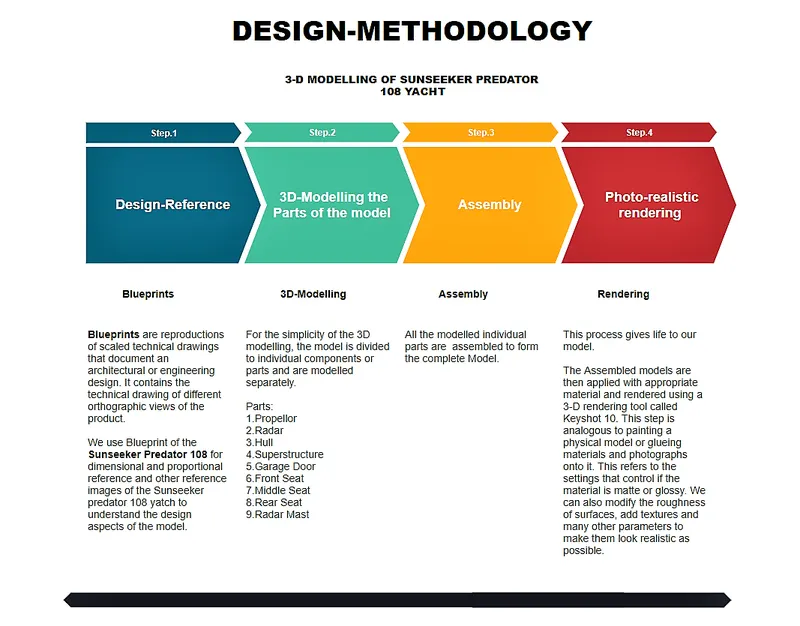
In this Project, we primarily focus on the visual aspects of the Model, so we can only try to achieve a fairly dimensionally accurate model in comparison to the real-life dimension. We use Blueprint of the Sunseeker Predator 108 for dimensional and proportional reference and other reference images of the Sunseeker predator 108 yacht to understand the design aspects of the model.
Blueprints are reproductions of scaled technical drawings that document an architectural or engineering design. It contains the technical drawing of different orthographic views of the product. The primary idea of the Blueprint/Plan is to bring out the exact shape and form of the product as intended by the designer.
Blueprint can be set up using Sketch mode in SolidWorks, it is important to understand the scale of the Blueprint and adjust it to the accurate scale.
Individual parts are then modelled using SolidWorks in reference to the blueprint as separate part files. These individual parts file can be assembled with appropriate geometric relationships with each other using Mates to create the complete assembly. Mates create geometric relationships between assembly components. As you add mates, you define the allowable directions of linear or rotational motion of the components. You can move a component within its degrees of freedom, visualizing the assembly's behaviour.
The Assembled models are then applied with appropriate material and rendered using a 3-D rendering tool called SolidWorks Visualize. This step is analogous to painting a physical model or glueing materials and photographs onto it. This refers to the settings that control if the material is matte or glossy. We can also modify the roughness of surfaces, add textures and many other parameters to make them look realistic as possible.
3-D Modelling in Solidworks
1.Propeller
Features Used:
- Sketch
- Revolve
- Plane
- Loft
- Plane
- Extrude cut
- Fillet
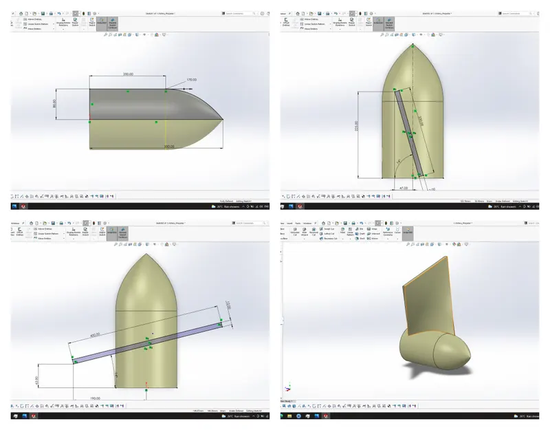
Using Sketch feature, the basic shape of the Propellor head is drawn and is revolved along its center axis using the Revole feature to complete the propellor head.
A new Plane is made above the propellor head at a distance of 360mm using the Plane feature. Using the Sketch tool, the profile of the blade is drwan on the newly created plane and the top plane. Using the Loft feature, the Blades are formed as shown in the picture above.
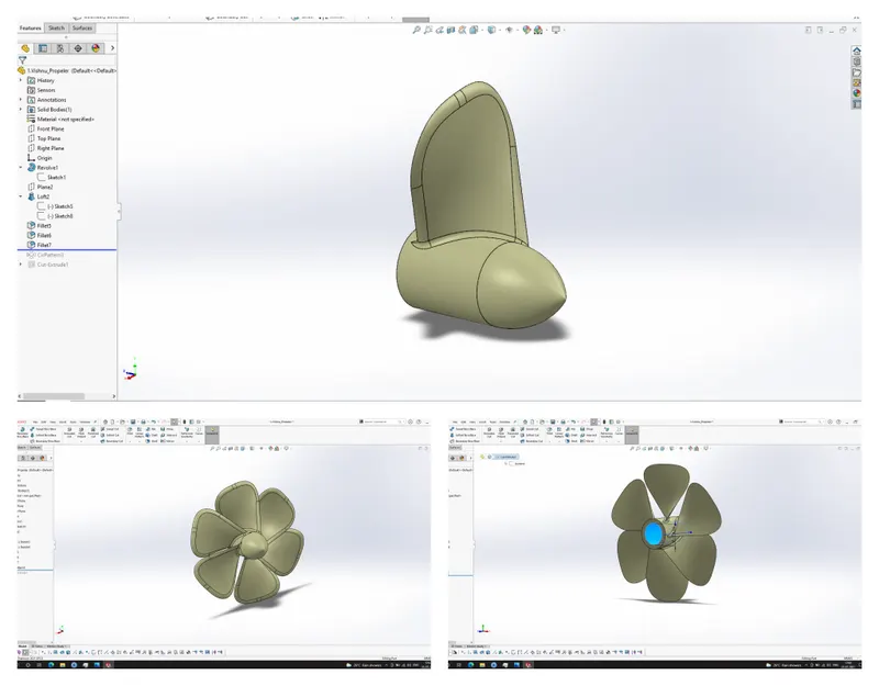
The Fillet feature is used to round the sharp edges of the blade. Multiple fillets are used to create the required shape of the blade.
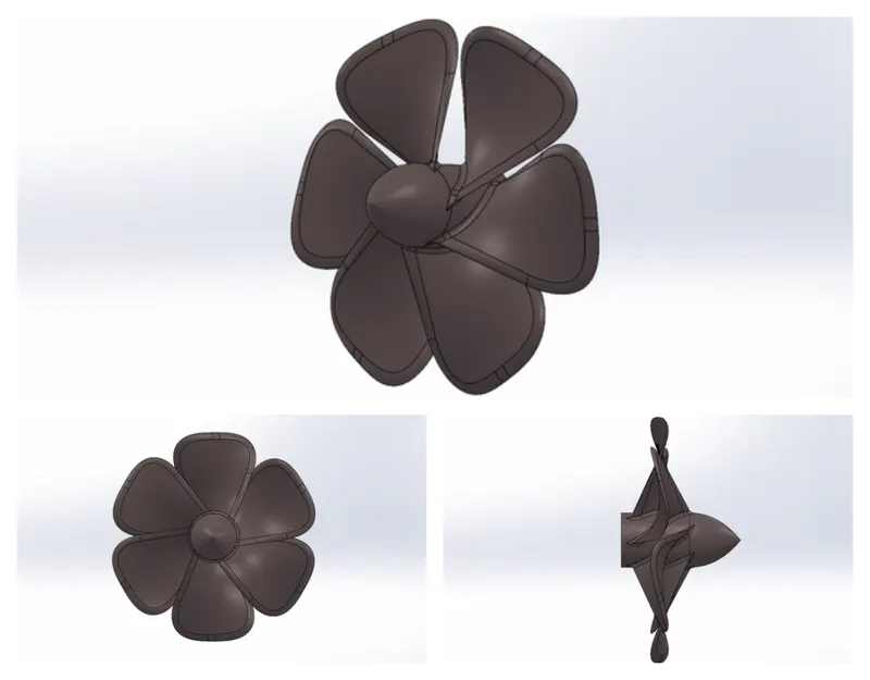
Finally, using the Sketch and Extrude-cut feature, an opening is made on the backside of the propellor head as shown in the above figure.
2.Radar
Features Used:
- Sketch
- Boss-Extrude
- Extrude cut
- Sketch Pattern
- Mirror
- Split line
- Fillet
- Chamfer
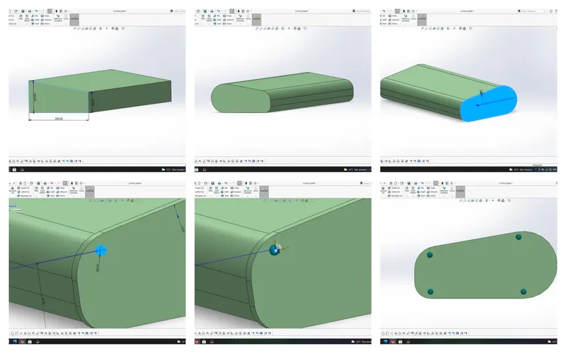
Using the Sketch and Extrude feature, the basic shape of the radar is created.
Fillet feature is used to round the sharp edges and create the intended shape.
Using the Sektch and Extrude feature, the basic shape of the screw head is created.The Fillet feature is used to round the screw head
Using the Sektch and Cut-Extrude feature, a hexagonal cut out is made.
Using the Sketch and Sketch pattern feature, positions of the other other screws are marked and basic shape of the screw head is drawn. the abave procedure is repeated to create the screws in the other marked locations.
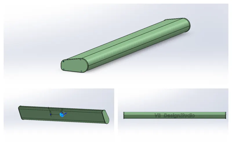
As the model we are creating is symmetrical, we only have to make one half of the model, other half can be copied using the Mirror feature as shown in the above figure.
Using the Sketch and Cut-Extrude feature, the mounting hole is created on the botttom surface of the radar, the Chamfer feature is used to bevel the sharp edges.
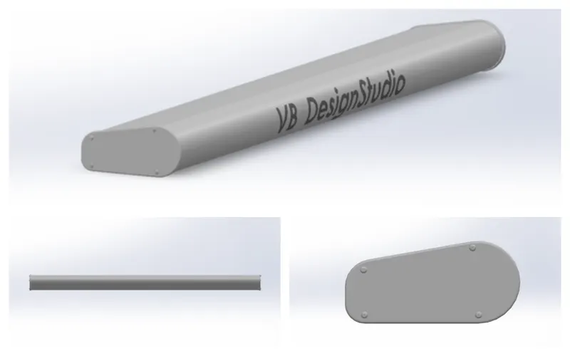
Using Sketch and Split-line feature, the surface can be split according to our desired wording or shapes.
3.Hull
Features Used:
- Sketch
- Sketch Picture
- Surface-Loft
- Surface-Trim
- Surface-Extrude
- Surface-Knit
- Shell
- Boss-Extrude
- Extrude-Cut
- Sweep
- Chamfer
- Linear Pattern
- Dome
- Helix/Spiral
- Delete/Keep Bodies
Since the shape of the model we ae creating is Symmetrical, we only have to create half of the model, rest half can be mirrored along the mid-plane to create the complete model.
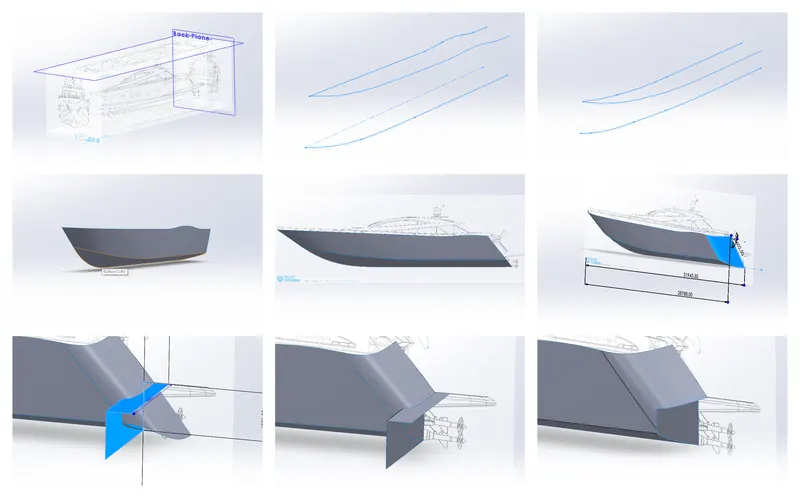
Using the Sketch and Sketch Picture feature, the blueprints are added to the respective planes and location and scale of the blueprints are adjusted accordingly. As we will be using the Blueprint set-up in modeling of other parts, the part is saved as a separate file.
Using the Sketch and Projected Curve feature, sketch of the profie of the curve is drawn in two planes of two different axis and is projected to create a intersecting curve.
Using the Surface-Loft feature, surface is created along the selected curve as shown in the above figure.
Using the Sketch and Surface-Trim feature, surfaces can be trimmed according to the selected sketch profile.
Uisng the Sketch and Surface-extrude feature, another surface is made as shown in the above figure and using the Surface-Trim feature, unwanted surfaces are trimmed. The Surface-Knit feature, all the surfaces can be combined to form a single joined surface.
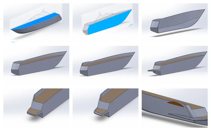
Using the Surface-Fill feature, the top surface and side surface are created. The model is converted to shell using the Shell feature.
Using the Sketch and Extrude feature, the Hull Floor and Extruded Base Floor is created.
Using the Sketch and Extrude-cut feature, The curved glass window is created.The Fillet feature is used to round the sharp edges of the Extruded base floor and the windows.
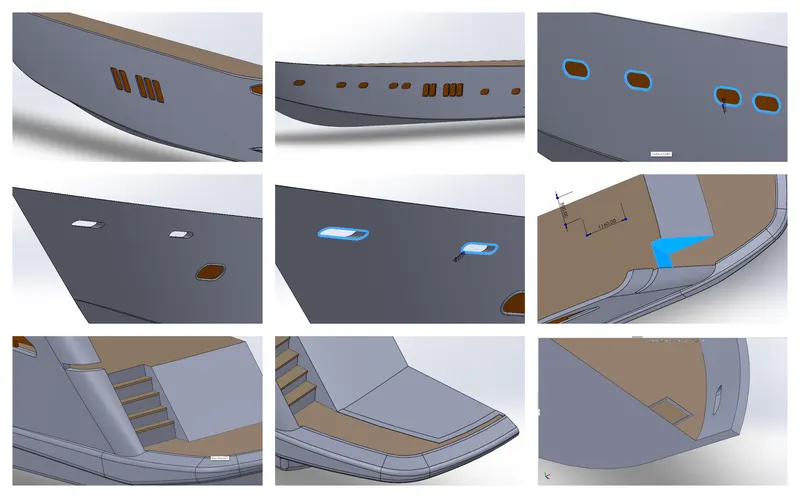
Using the Sketch and Extrude-Cut feature, the windows are cut out as shown in the above figure.
Using the Sketch and Sweep feature, the borders of the windows are made as shown in the above figure.
Using the Sketch and Extrude-Cut feature, the location for the stairs are cut from the Hull body, then the stairs are made using the Sketch and Extrude.
Using the Sketch and Extrude feature, the Border of the Swim Platform and Storage door is created. Using the Fillet feature, the sharp edges are rounded.
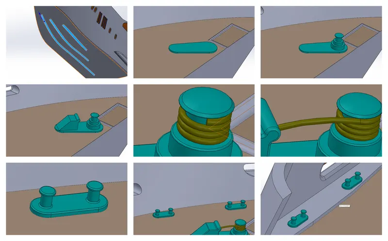
Using Sketch and Extrude feature, the ridges below the hull is made. Using the Fillet and Chamfer feature, the sharp edges are rounded and the required shape is attained.
Now to make the Achor wire holding pole, Sketch and Extrude feature is used to make the base.
Using the Sketch and Revolve feature, the pole is created as shown in the figure. Using the Dome feature curved surface on the top of the pole is created.
Using the Extrude and Cut Extrude feature, the wire hole casing is created. Using Fillet feature, the sharp edges are rounded off.
Using the Helix/Spiral and Sweep feature, the curled anchor wire is created.
Similarly using the Sketch and Extrude feature, the other hook features are created and using Linear Pattern, the hook feature is repeated to different location according to the blueprint.
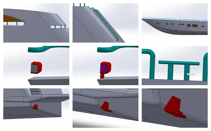
Using the Sketch and Sweep feature, the railings are created as shown in the above figure.
Using the Sketch and Extrude feature, the Front Light casing and stand is created. Fillets are added to round the sharp edges.
Similarly, using the Sketch and Extrude feature, the actuator mount is created as shown in the figure.
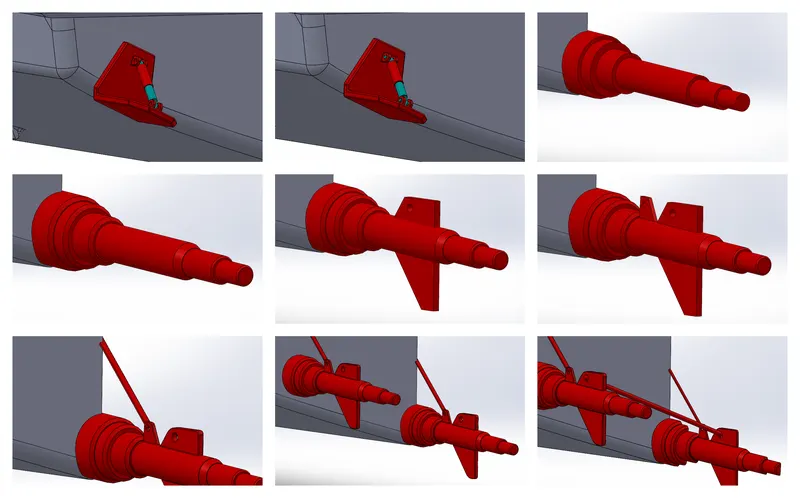
Using the Sketch and Revolve feature, the actuator rod is created. Similarly, the Propeller axle is created.
The Fillets and Chamfer feature is used to round the sharp edges.
Using the Sektch and Extrude feature, the Fins are made on the axle casing. holes are cut on the fins using the Extrue-Cut feature.
Similarly,using the Sektch and Extrude feature, the connecting rods are made.
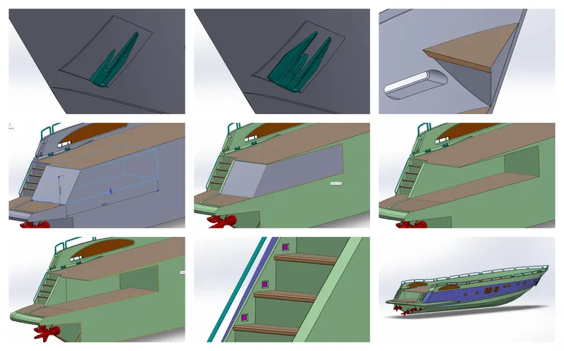
Using the Sektch and Extrude feature, the Front Hook of the yatch is made, exact shape is acquired using the Chamfer and Fillet feature. The Mirror feature is used to complete the Hook.
Similarly using the Sektch and Extrude feature, the Bow seat is created. The sharp edges are rounded using the Fillet feature.
Using the Sketch and Extrude-Cut feature, Garage space is created and the part is saved to separate solid part using Keep Bodies feature and save it as Garage_door.sldprt
Using the Combine feature, all the separate bodies are combined together to create a single body.
Using the Sketch and Extrude-Cut feature, stair lights are created as shown in the above figure.
Finally, Using the Mirror feature, the created body is mirrored about mid-plane to create the complete Hull structure.
4.Garage Door
Features Used:
- Sketch
- Boss-Extrude
- Extrude cut
- Shell
- Mirror
- Fillet
- Delete Face
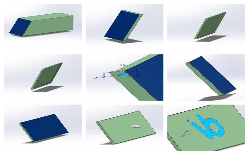
Here we start with the previously saved part Grage_door.sldprt while creating the Hull structure.
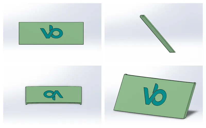
Using the Sketch and Extrude-Cut feature, the Basic shape of the door is created. Fillets are added to round the sharp edges of the Garage Door.
Using the Shell feature, the inner part of the garage door is created as shown in the above figure.
Using the Sketch and Extrude-Cut feature, the mounting hole on the garage door is created.
Using the Mirror feature, the body is mirrored about the mid-plane to create the complete Body.
Using, Delete face and Tangent Fill feature, the outer surface of the Garage door is converted to single surface.
Finally using Sketch and Extrude-Cut feature, the VB Design Studio Logo is cut out from the garage door surface as shown in the above picture.
5.Superstructure
Features Used:
- Sketch
- Sketch Picture
- Ruled-Surface
- Surface-Loft
- Surface-Trim
- Surface-Fill
- Surface-Extrude
- Surface-Knit
- Boss-Extrude
- Extrude-Cut
- Combine
- 3-D Sketch
- Sweep
- Chamfer
- Linear Pattern
- Dome
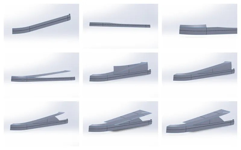
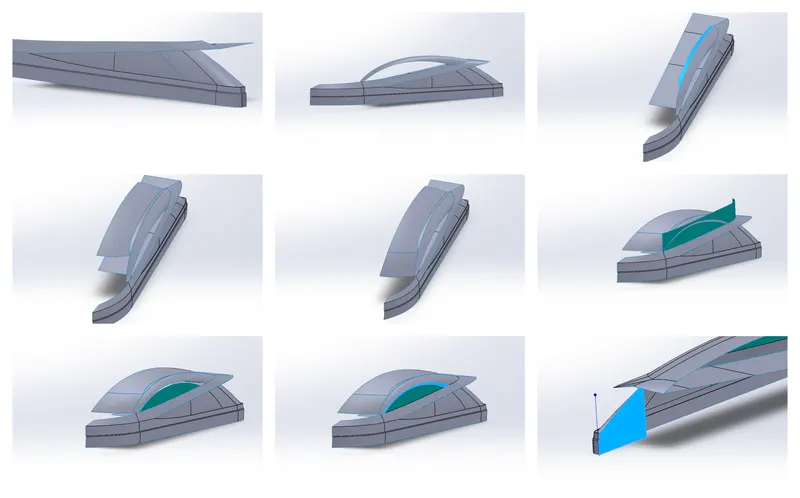
Similarly, The method we used to make the Hull structure is followed here, We use Surface tools make to make complicated shapes like the Hull and the Superstructure. Here in this procedure we use surafce toos like Surafce Extrude, Surface-Loft, Surface-Sweep, Ruled-Surface, Surfcace-Fill and Surface-Extend to create the surfaces according to the Sketch we have selected.
Surface-Trim feature is used to to cut and delete the unwanted surfaces. In thsi feature, it provides the option to selct the Cutting surface and the Surface to cut. Once the surface is split, we are given the option to select and delete the unwanted surface or Select and Keep the required Surface.
Surface-Knit feature is used to , as the name suggests , knit or merge the selected surface to make a single joined surface.
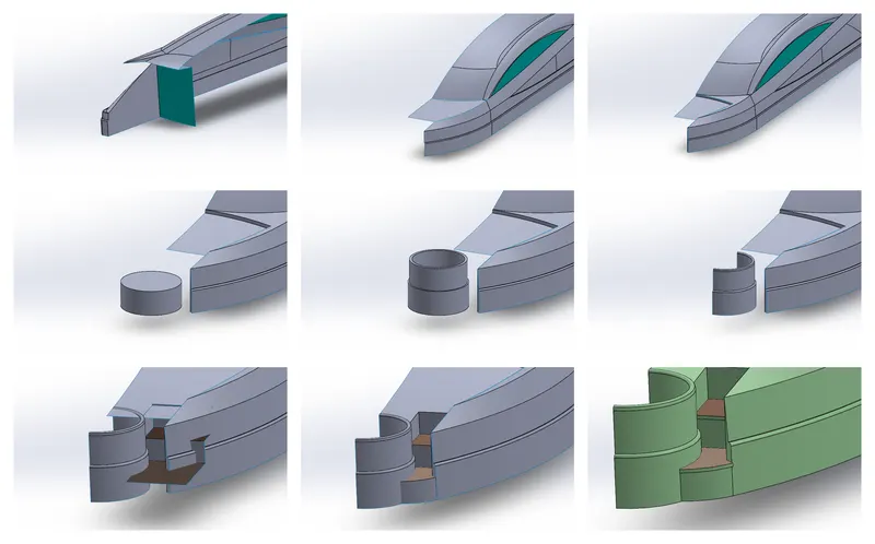
Using these Surface tools, the Basic Shape of the superstructure is made as shown in the above Figure.
The Jacuzzi is made using the Sketch and Extrude feature. Then the Hole is cut out using the Extrude-Cut feature. The Sharp edges are rounded using the Fillet Feature. Usign the Extrude-Cut feature, the Jacuzzi is cut into Half as we are modelling a symmetrical body, we will be mirroring it to the other side to complete the Model.
Using the Surface-Extrude and Surface-Trim tool, the Jacuzzi stairs are made as shown in the above picture.
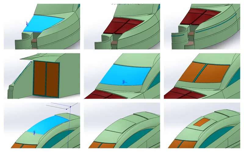
Using the Surface-Thicken feature, the Spa bed is extruded upwards, then using the Extrude-Cut feature, the bed is split into two parts. Fillets are added to round the sharp edges of the bed. The Dome feature is used to create the bump on the bed, this makes the bed look more realistic.
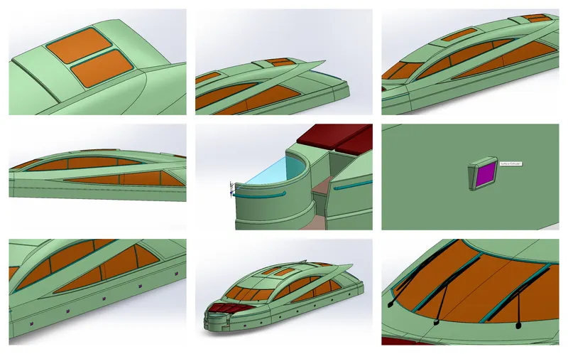
Using the Extrude Cut ad Extrude feature, the Windsheild,Top galsses and its Steel Framings are made. The Fillet feature is used to round the Railing edges. Similarly, using the same method, the side window and its framings are made.
Using Surafce-Extrude feature is used to create the Jacuzzi water surface.
Using the Extrude and Extrude-Cut feature, the side lights are created. It is important to not Merge the Side light body with the main structure, so that the silde light can be patterned along the main body using the Linear-Pattren feature.
Now using the Combine feature, all the separate bodies are Combined together to form a single Body, so that it can be mirrored along the Mid-plane using the Mirror feature to complete the model.
Extrude and Extrude-cut feature is used to make the windshield wipers. Loft and 3-D sketch feature is used to make the winper connecting handle.Finally, using the Fillets and Chamfer feature the sharp edges are rounded and beveled to create the intended shape.
6.Front Seat
Features Used:
- Sketch
- Ruled-Surface
- Surface-Loft
- Surface-Trim
- Surface-Fill
- Surface-Extrude
- Surface-Knit
- Surface-Revolve
- Boss-Extrude
- Extrude cut
- Mirror
- Fillet
- Chamfer
- Dome
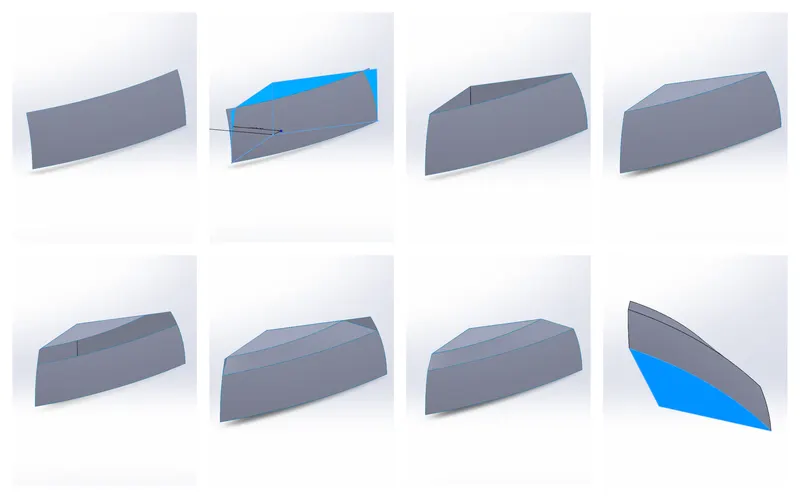
Similar to the procedure we used to make the Hull and Superstrycture, we use surafce toos like Surafce Extrude, Surface-Loft, Surface-Sweep, Ruled-Surface, Surfcace-Fill and Surface-Extend to create the surfaces according to the Sketch we have selected.
Surface-Trim feature is used to to cut and delete the unwanted surfaces. Using the Surface-Knit feature all the seperate surfaces are combined to make a single joined surface. Chamfer feature is used to bevel the side of the seat structure.
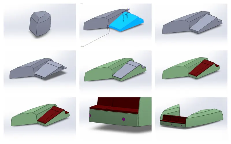
Revolve feature is used to extrude the Seat portion as shown in the Figure. Similarly to extrude the base portion of the seat and bed surface, Surface-revolve feature is used. Extrude-Cut feature is used to cut the body along the mid-plane, so the the body can be mirrored along the Mid-plane later when one side the model is fully completed.
Using the Extrdue-Cut feature, the sofa and bed is split into seperate bodies. Finally, using the Fillet feature ,the sharp edges are rounded to created the Sofa and the Bed.
Now the Extruded-cut feature is used to create the Front seat lights as shown in the above picture.
Finally, all the body is mirrored about the Mid-plane using the Mirror feature to complete the model.
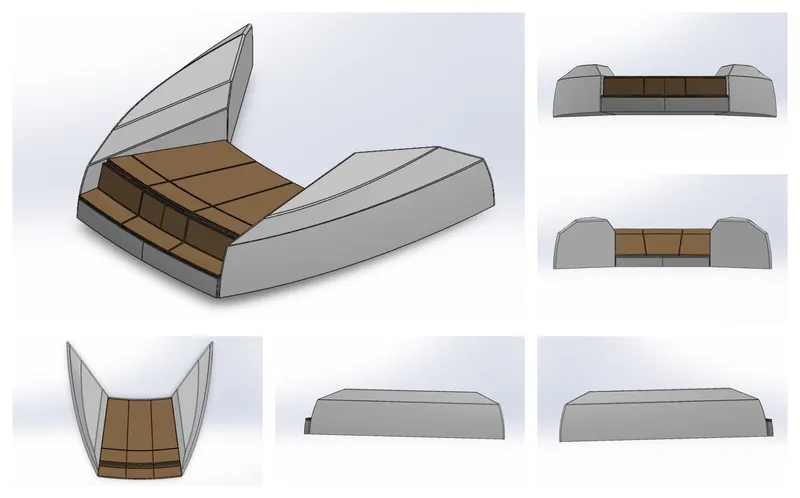
7.Front Seat
Features Used:
- Sketch
- Boss-Extrude
- Extrude cut
- Mirror
- Fillet
- Chamfer
- Revolve
- Dome
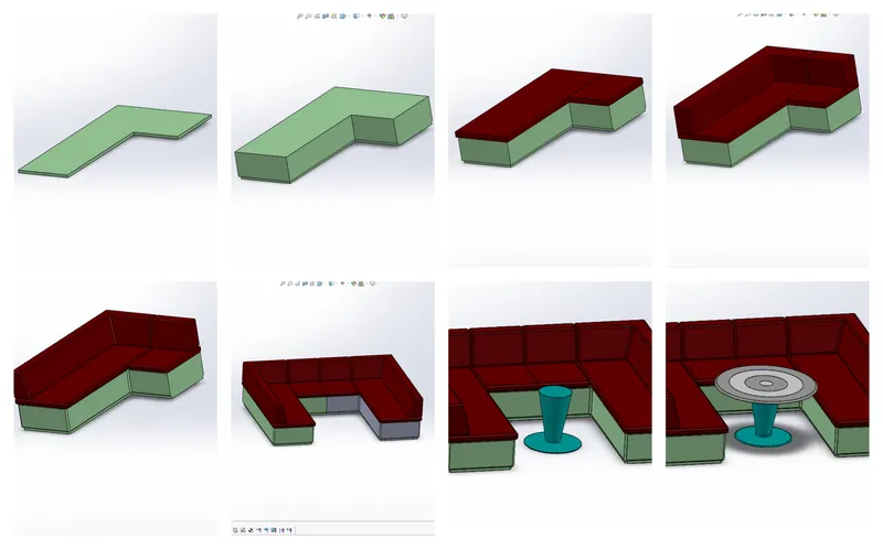
Here, again as the model is Symmetric , we only have to create the one half side of the model rest vcan the mirroed along the mid-plane to create the complete model. As the model is mostly regualr shapes , we do not require any surface modeling tools to create this model.
Using the Skecth and Extrude feature the base of the Sofa is made.Similarly, Seat deck, Seat cushions and Back cushions are made.
Fillet feature is used to round the sharp edges of the model. Chamfer feature is use dto bevel the Back cushion in the the required angle as shown in the above picture.
Finally, using the Mirror feature , the Sofa is mirrored along the mid-plane to create the complete model.
To create the Center-Table , Revolve feature is used and the sharp edges are rounded and beveled using Fillet and Chamfer feature.
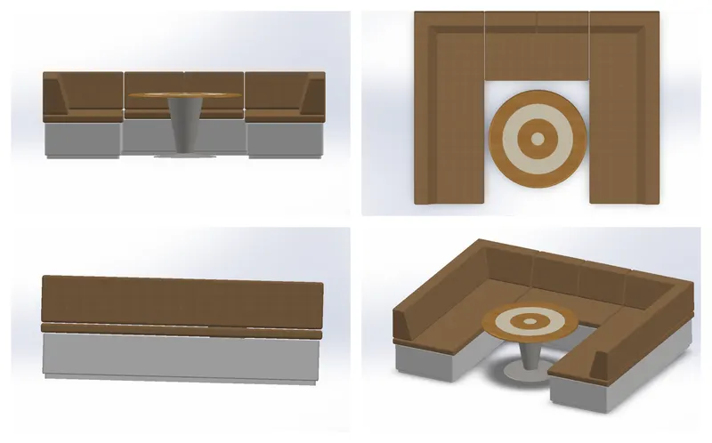
8.Rear Seat
Features Used:
- Sketch
- Ruled-Surface
- Surface-Loft
- Surface-Trim
- Surface-Fill
- Surface-Extrude
- Surface-Knit
- Surface-Revolve
- Surface-Offset
- Boss-Extrude
- Extrude cut
- Mirror
- Fillet
- Chamfer
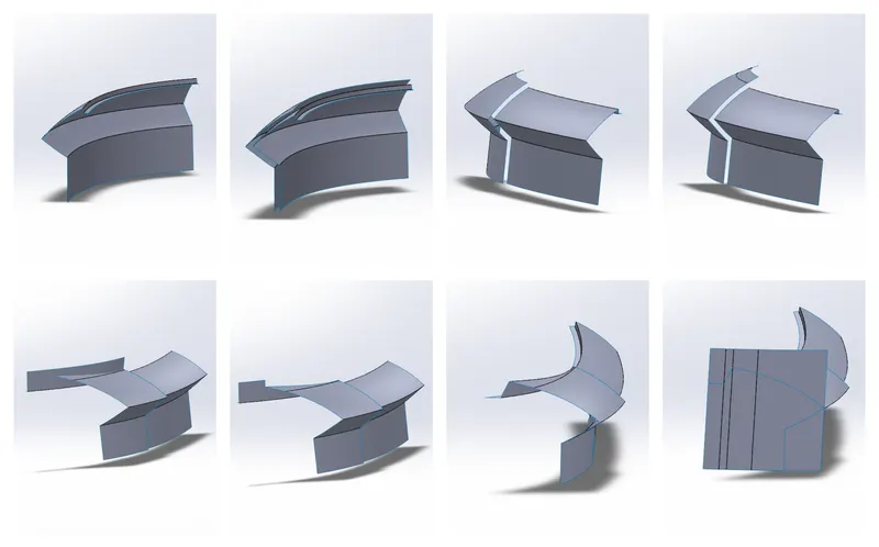
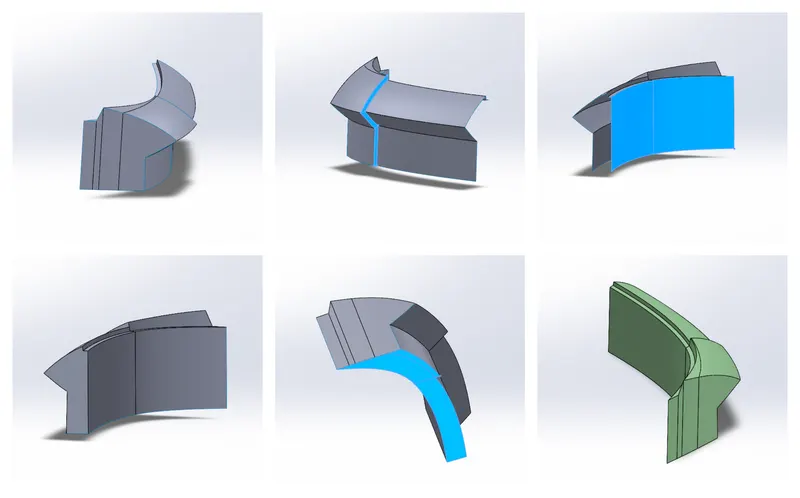
Similar to the procedure we used to make the Hull and Superstrycture, we use surafce toos like Surafce Extrude, Surface-Loft, Surface-Sweep, Surface-Offset, Surfcace-Fill and Surface-Extend to create the surfaces according to the Sketch we have selected.
Surface-Trim feature is used to to cut and delete the unwanted surfaces. Using the Surface-Knit feature all the seperate surfaces are combined to make a single joined surface and covert to solid body option is selected.
The solid body is then mirrored about the Mid-plane using the Mirror feature to complete Rear seat structure.
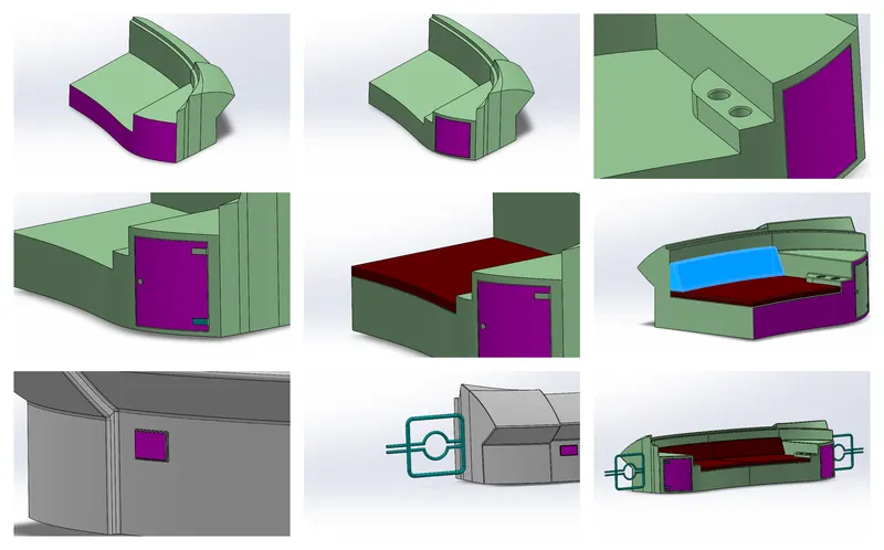
Using the Sketch and and Extrude feature, the seat platform is made.
Similarly, the cup holder platform is created using the Extrude feature, the Cup holder holes are created using the Exttrude-cut feature.
Using the Sketch and and Extrude feature, the seat cushion and the back cushion is created. Using the Fillet, the shrap edges of the cushions are rounded and using the Chamfer feature, the back cushion is beveled at an angle to produce the required shape.
To create the Storage compartment, Extrude-cut feature is used. The Compartment handle and the Hinges are created using the Extrude feature.
The Sektch and Sweep feature is used to create the Side Steel doors.
Using the Sketch and and Extrude feature, the rear seat lights arer created.
All the sharp edges are rounded using the the Fillet feature.
Finally, using the Combine feature, all the seperate bodies are combined to single part and then mirroed about the mid-plane to complete the Model.
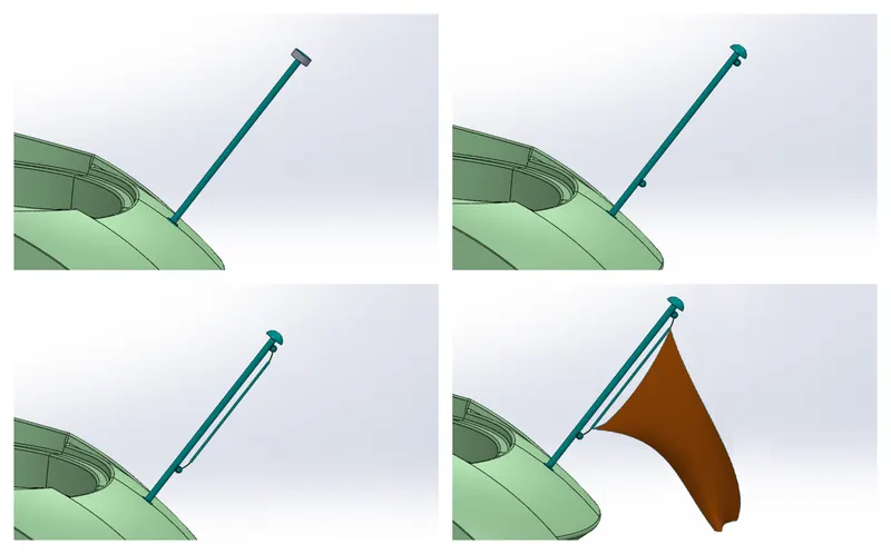
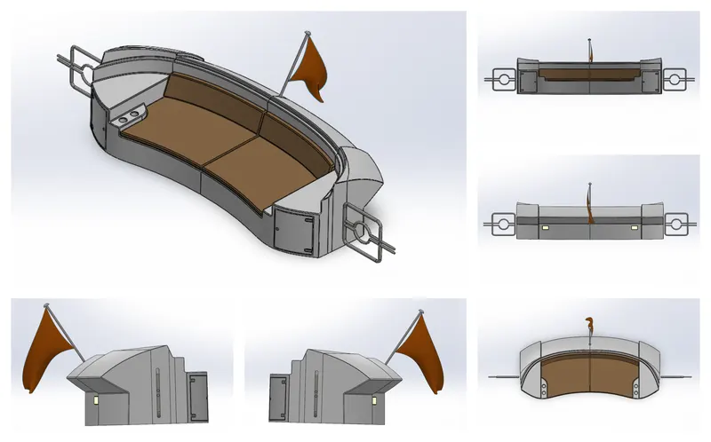
Flag pole is created using the Sketch and Revolve feature,then Using Sweep feature, the the flag thread is created.
Finally, uisng the 3-D sketch feature, 4 sides of the flag are drawn in reference to the blueprint.
The Flag pole body is combined with the main body using the Combine feature.
9.Radar Mast
Features Used:
- Sketch
- Boss-Extrude
- Extrude cut
- Mirror
- Fillet
- Chamfer
- Revolve
- Dome
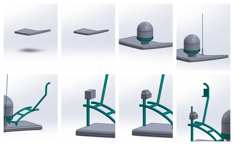
Using the Skecth and Extrude feature, the Base platform is extruded. Sharp edges are rounded using the Fillet feature.
Similarly, the Radar antenna is extruded using the same method.
Using the Skecth and Revolve feature, the marine Satellite Dome is created.
Using the Skecth and Extrude feature, the radar stand is created. Fillets are added to round the sharp edges and Chamfer feature is used to bevel the model in the required shape.
Using the Sketch and Sweep feature, the railing structure is created.
The Skecth and Extrude feature is used to created the Top light mounting platform.
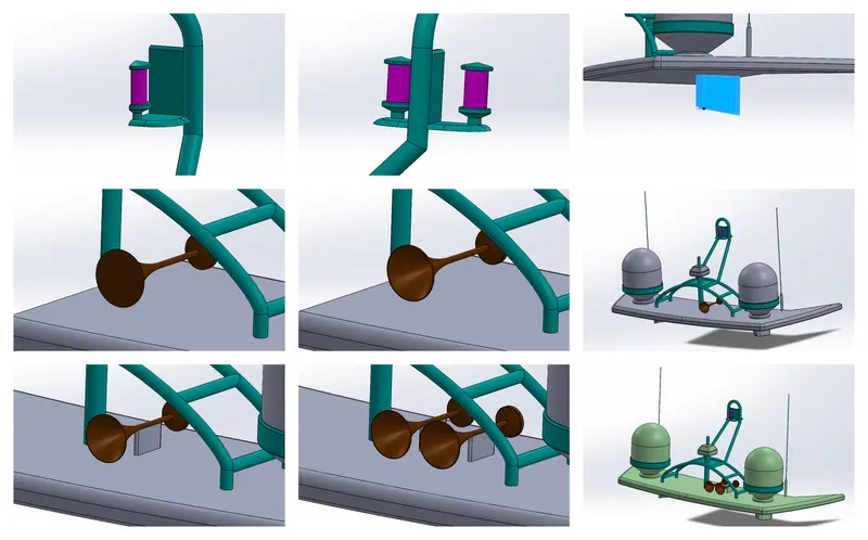
Using the Extrude feature, the legs for the radar platform is created. The Revolve feature is used to create the Top lights and the Air Horn of the Yacht.
The Shell feature is used to convert the solid body to hollow body with the mentioned thickness.
Using the Extrude feature, the leg of the Air horn is created.
The Mirror feature is used to mirror the Top Light to another side. Similarly, the Air Horn and its leg is copied to the other side as shown in the above picture.
Finally, the all the separate bodies are combined together using the Combine feature and then its is mirrored about the mid-plane using the Mirror feature to complete the whole structure.
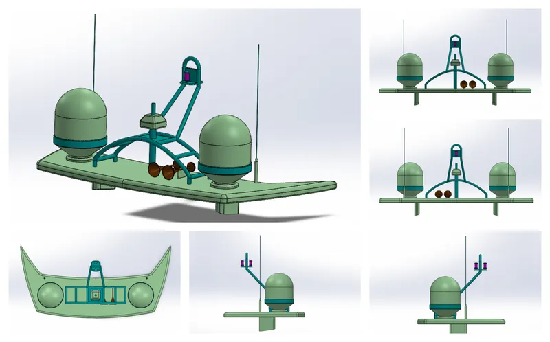
Assembly of all the Individual Parts into a Single Unit
In the Assembly modelling, each part is inserted and assembled to create the complete model of the American Chopper.
In an assembly, the analogy to sketch relations is Mates. Just as sketch relations define conditions such as tangency, parallelism, and concentricity with respect to sketch geometry, assembly mates define equivalent relations with respect to the individual parts or components, allowing the easy construction of assemblies. Mates define the allowable direction of linear or rotational motion of the components. The component can be moved within its degree of freedom.
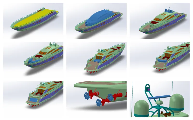
- Initially, the Hull is inserted into the assembly environment and is fixed at its default location.
- Similarly, the Superstructure, Front seat, Middle Seat, Rear seat and Radar Mast Assembly are inserted and fixed on to its default location. This is done because, for all these parts we have used the same Blueprint setup as the reference so , by default the location of these parts are already on position.
- To Fix the Garage door on to the Hull structure, a Coincident mate realtion is applied to the mid-plane of Garage door and the mid-plane of the Hull. To constrain the Garage door in the correct location , another Coincident mate relation is added between the Garage Hinge hole surface and Garage hinge rod surface.
- To fix the Propellor fan, a Coincident mate realation is added between the inner curved surface of the Propeller blade hole and the outer curved surfcace of the mounting rod. To constrain it to position another Coincident mate realation is applied between the top surface of the peopellor hole and interacting surface of the mounting rod. All the three propellers are fixed to its position using the same method.
- Finally, the Radar is fixed on to its position by adding a coincident mate realation between the Bottom surface of the Radar bottom hole and the Top surface of the mounting rod. To constrain its location , another Coincident mate is applied between the curved surface of the Radar bottom hole and the curved surface of the mounting rod.
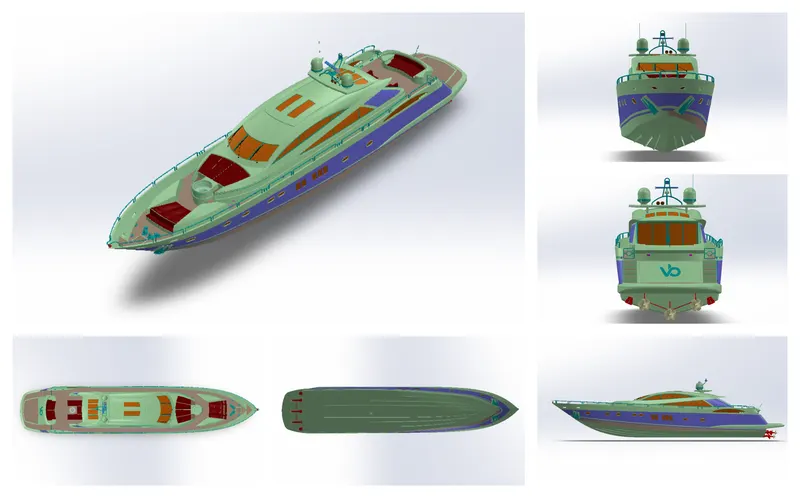
Rendering of the Sunseeker Predator 108 Yacht
Rendering or image synthesis is the process of generating a photorealistic or non-photorealistic image from a 2D or 3D model using a computer program. The resulting image is referred to as the render.
There are many softwares availble to do the process of rendering. Some of the Major rendering softwares are SolidWorks visualize, Keyshot, V-ray.
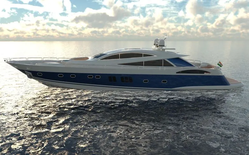
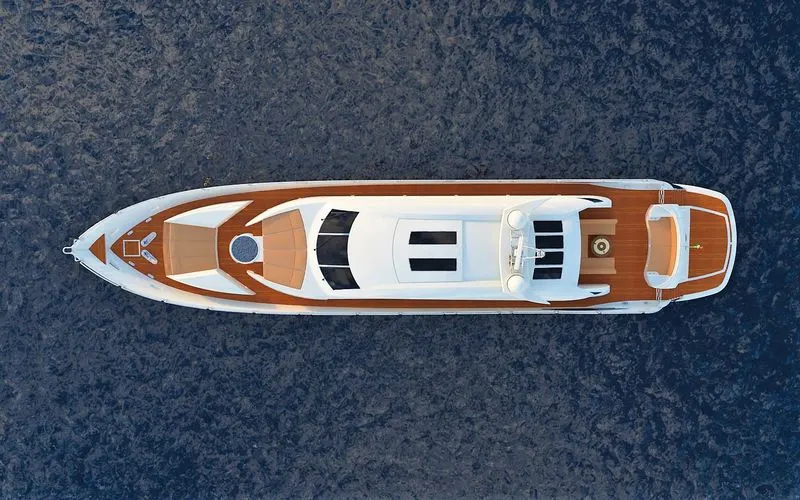
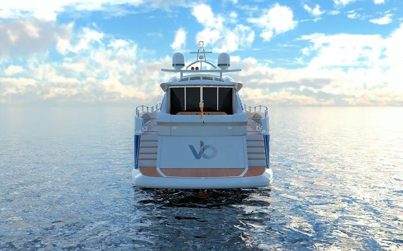
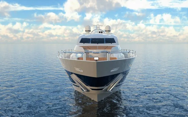
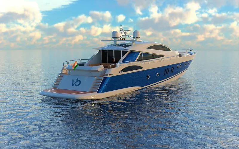
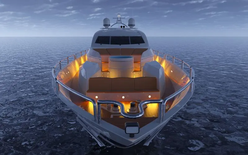
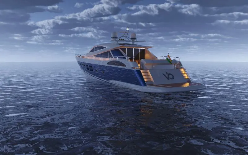
Here I have used Keyshot 10 for the rebdering of the Sunseeket Predator Yacht. KeyShot is real-time ray-tracing and global illumination program used to create 3D renderings, animations and interactive visuals. With the CPU-based architecture, photo realistic real-time rendering can be achieved even on simple laptops without the need for special graphics cards. It supports import for the greatest number of 3D file formats out of any rendering software, importing over 20 different file types, has an incredibly simple user interface with drag-n-drop material and environment presets, interactive labeling, texture mapping, physical lighting, animation and much more.
Initially, The model is imported into the Keyshot sofware. In the above ictures of the Yacht assembly, you can notice that I have separated each parts with different colours according to their material, This is good practice, as doing so helps the Keyshot Software to differentiate and group the parts with simliar material together, this saves a lot of time while applying material.
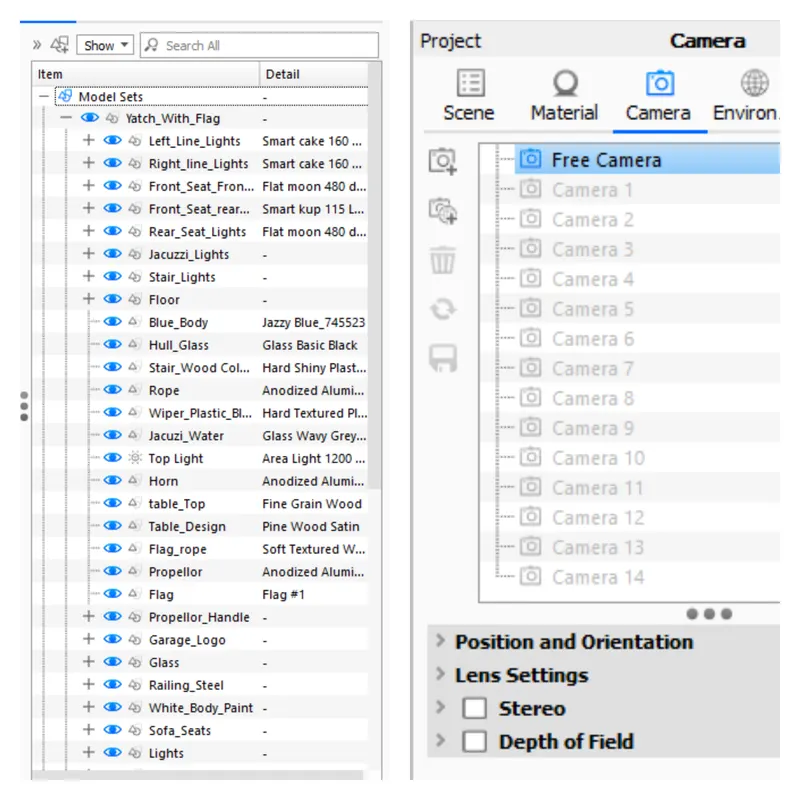
Keyshot has a wide variety of materials and lights in their material library, appropriate materials are added to each parts. IES lights are added into the model in required places.
In keyshot, additional geometry can be added using add geometry feature. Here for the Sea I have created a large cuboid and then placed the Yacht model such a way that its bottom looks submerged in the water. To create the Sea, I have applied a glass material with a Noise texture and scaled the texture size to an appropriate size.
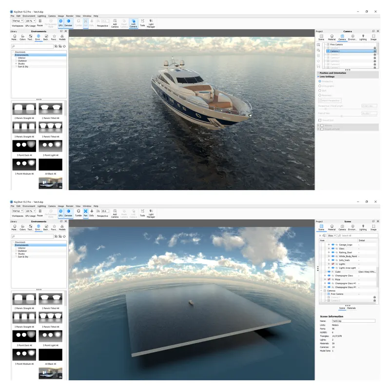
Once the model is set up with materials and decals, the environment and lighting can be set up. To create a Photo-realistic render, we use High-quality HDRi maps for our environment lighting. HDRi (High Dynamic Range Image) is a panoramic photo, which covers all angles from a single point and contains a large amount of data, which can be used for the illumination of a CG scene.
Multiple cameras can be set up with different views and angles. Once the cameras are set up, the positions of the cameras can be locked and all the camera views can be toggled between each other with a single click. Multiple scenes can be rendered using the queue to render or schedule render options.
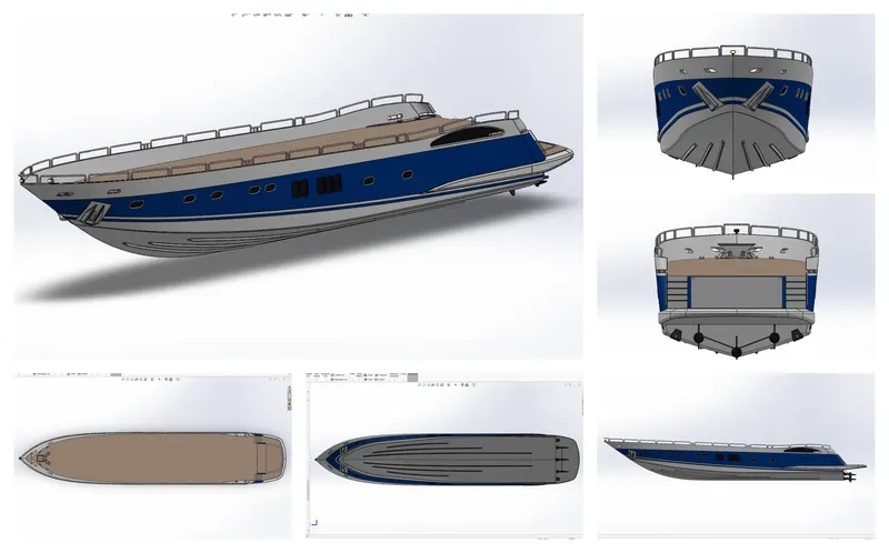
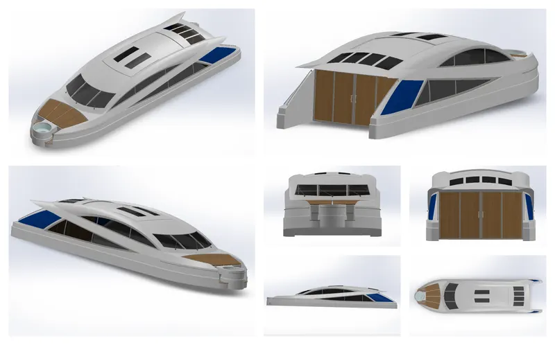
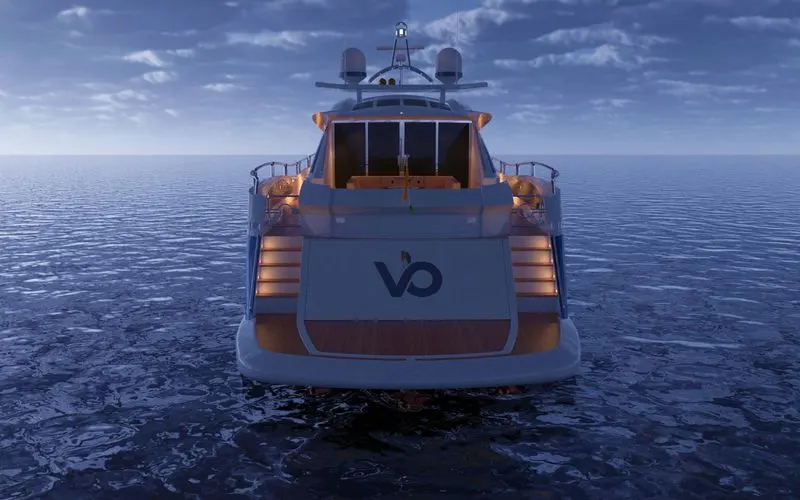
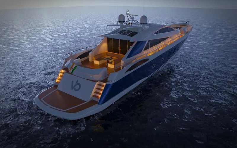
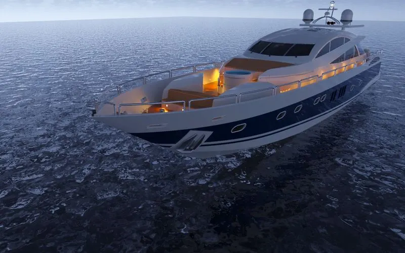
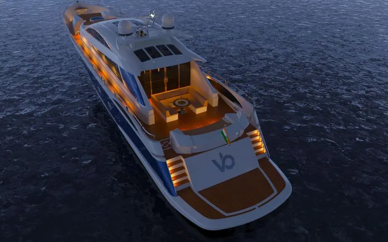
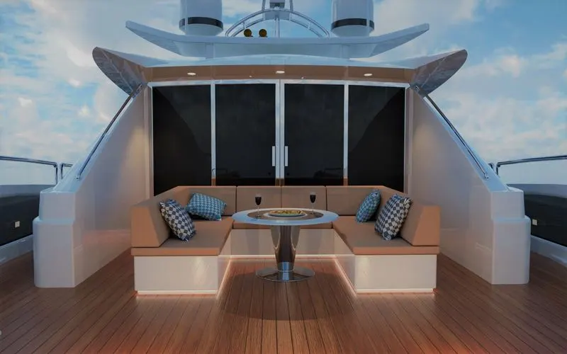
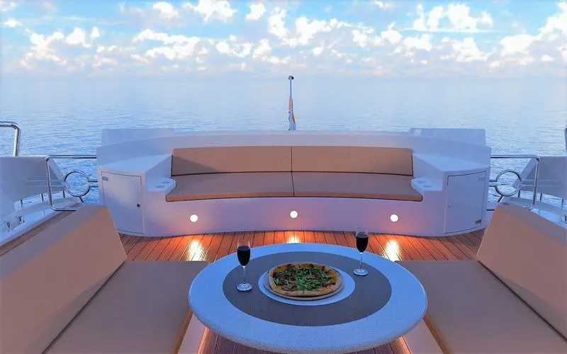
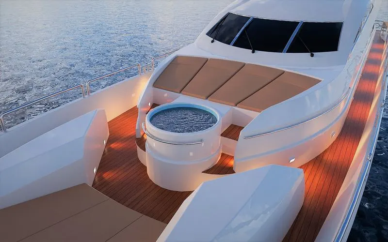
Some of the rendered images of the Sunseeker Predator 108 Yacht are as shown below :
Conclusion:
The main idea of this project was to learn the Solidworks software, understand its different tools, features and know-how these tools can be utilized in a professional environment. This project primarily focuses on the Surface modeling and its tools where any complicated shapes can be made easily.
A better understanding of - The modelling approach on how an existing product is converted into a 3-D model part by part from scratch and then assembling each component to complete the assembly is achieved through this project.
A better understanding of - How high-quality renders of the 3-D model are produced, How materials and textures are applied on the 3-D Models, How multiple cameras, environment and lightings are set up for the renders, How different parameters in the settings and features in the rendering software affects the render-outputs, all are acheived throuh this project.