Photo Realistic Rendering
3-D Modelling of an American Chopper
Introduction:
SolidWorks is a solid modelling computer-aided design (CAD) and computer-aided engineering (CAE) computer program published by Dassault Systems. It has the most efficient and powerful CAD design collection available for product and part assembly designers.
SolidWorks is a solid modeller and utilizes a parametric feature-based approach to create 3d models. Parameters refer to constraints whose values determine the shape or geometry of the model or assembly. Parameters can be either numeric parameters, such as line lengths or circle diameters, or geometric parameters, such as tangent, parallel, concentric, horizontal or vertical, etc. Numeric parameters can be associated with each other through the use of relations, which allows them to capture design intent.
Building a model in SolidWorks usually starts with a 2D sketch. The sketch consists of geometry such as points, lines, arcs, conics, and splines. Dimensions are added to the sketch to define the size and location of the geometry. Relations are used to define attributes such as tangency, parallelism, perpendicularity, and concentricity. The parametric nature of SolidWorks means that the dimensions and relations drive the geometry, not the other way around. The dimensions in the sketch can be controlled independently, or by relationships to other parameters inside or outside the sketch.
In an assembly, the analogy to sketch relations is mates. Just as sketch relations define conditions such as tangency, parallelism, and concentricity with respect to sketch geometry, assembly mates define equivalent relations with respect to the individual parts or components, allowing the easy construction of assemblies.
Drawings can be created either from parts or assemblies. Views are automatically generated from the solid model, and notes, dimensions and tolerances can then be easily added to the drawing as needed.
SolidWorks has also developed an add-in called PhotoView 360, that produces photo-realistic renderings of the models created in SolidWorks. The rendered image incorporates the appearances, lighting, scene, and decals included with the model. SolidWorks Visualize is a standalone application from SolidWorks that enables design teams to produce photorealistic marketing content that communicates a design’s vision, passion, and emotion.
Objectives:
The main objective of this project is to create a 3D-Model of an American Chopper Bike and create a Photo-realistic rendering of the created model.
The modelling part can be divided into two parts as follows:
- Creating individual parts using SolidWorks.
- Assembling all the individual parts to create the complete model.
The Rendering the model can be divided into three parts as follows:
- Applying the appropriate materials and decals into the model.
- Setting up the Positions, Cameras, Environment and Lights.
- Rendering high-quality images of the model using PhotoView 360 and SolidWorks Visualize.
Design Methodology:
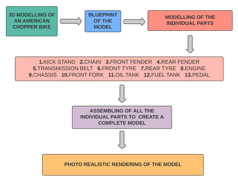
In this Project, we primarily focus on the visual aspects of the Model, so we can only try to achieve a fairly dimensionally accurate model in comparison to the real-life dimension. We use Blueprint of the American chopper for dimensional and proportional reference and other reference images of the chopper to understand the design aspects of the Chopper.
Blueprints are reproductions of scaled technical drawings that document an architectural or engineering design. It contains the technical drawing of different orthographic views of the product. The primary idea of the Blueprint/Plan is to bring out the exact shape and form of the product as intended by the designer.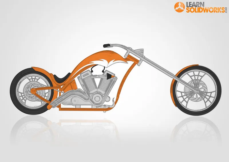
Blueprint can be set up using Sketch mode in SolidWorks, it is important to understand the scale of the Blueprint and adjust it to the accurate scale.
Individual parts are then modelled using SolidWorks in reference to the blueprint as separate part files. These individual parts file can be assembled with appropriate geometric relationships with each other using Mates to create the complete assembly. Mates create geometric relationships between assembly components. As you add mates, you define the allowable directions of linear or rotational motion of the components. You can move a component within its degrees of freedom, visualizing the assembly's behaviour.
The Assembled models are then applied with appropriate material and rendered using a 3-D rendering tool called SolidWorks Visualize. This step is analogous to painting a physical model or glueing materials and photographs onto it. This refers to the settings that control if the material is matte or glossy. We can also modify the roughness of surfaces, add textures and many other parameters to make them look realistic as possible.
Modelling of Individual Parts
1.The Transmission Belt
Features Used:
- Sketch
- Extrude Boss/Base
- Appearances
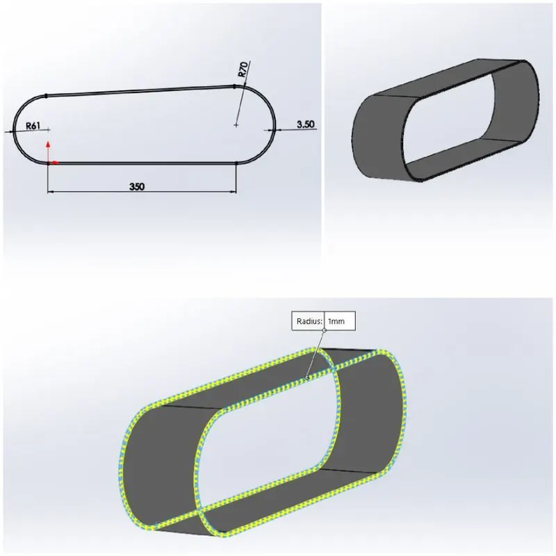
In SolidWorks Modelling, the initial step of modelling is to create a 2-D sketch of the Basic shape of the part. To do that we select the appropriate plane and use the Sketch feature to create the 2-D sketch of the basic shape as shown in the figure. Tools used to create the sketch are Line, 3-point Arc, Offset and Smart dimension.
To convert the created 2-D Sketch to 3-D, we use the Extrude Boss/Base feature. This feature helps you to extrude the 2-D sketch along its 3rd Axis, thus giving it its 3rd dimension. The Fillet feature is used to round off the flat edges of the 3-D model created. A Fillet radius of 1mm is applied to the edges as shown in the figure.
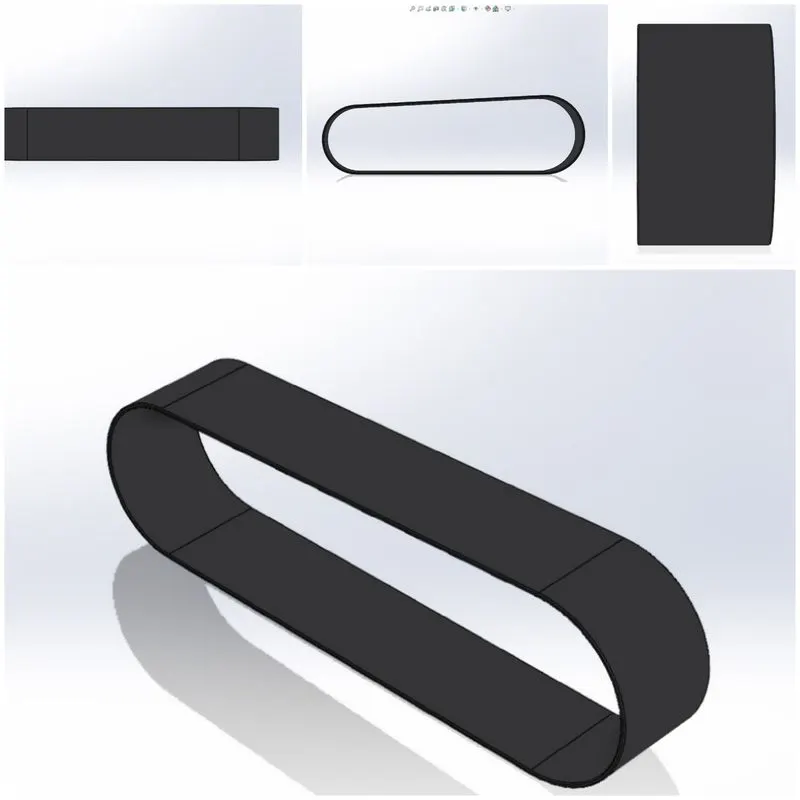
Using the Appearance feature, an appropriate material can be added to the model. This provides our model with better visual aspects.
2.KickStand
Features used:
- Sketch
- Loft
- Dome
- Extrude Boss/Base
- Extrude Cut
- Fillet
- Split
In the modelling of complex shapes, we can use multiple 2-D sketches in appropriate planes to define the shape of the model. In this particular case, we use 3 sketches to define the shape of our model. The sketches as shown in the figure below.
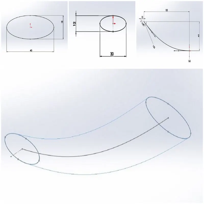
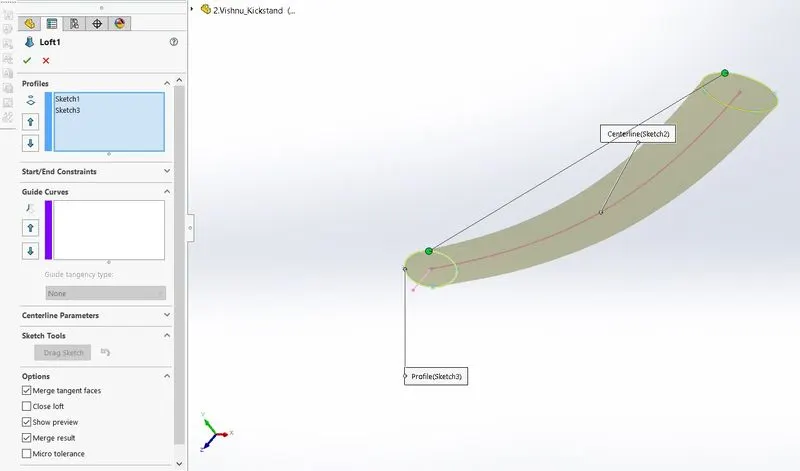
Now using the Loft feature, we can convert our 2-D sketches into the 3-D model. Sketch 1 and 3 are selected as the profiles to loft and Sketch 2 is used as the path/guide. Now the 2 profiles are connected along the mentioned path, thus creating a 3-D shape and intended.
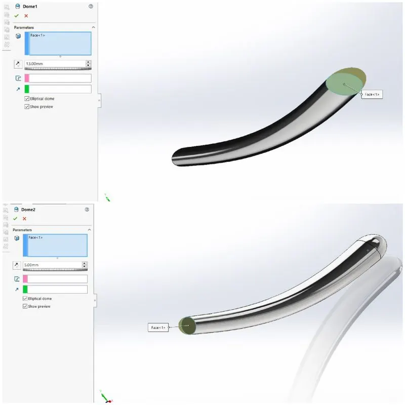
Using the Dome feature, a Dome can be created on the selected face. An appropriate height can be applied to the dome in the height section and also provide an Elliptical shape to the dome by selecting the elliptical dome option.
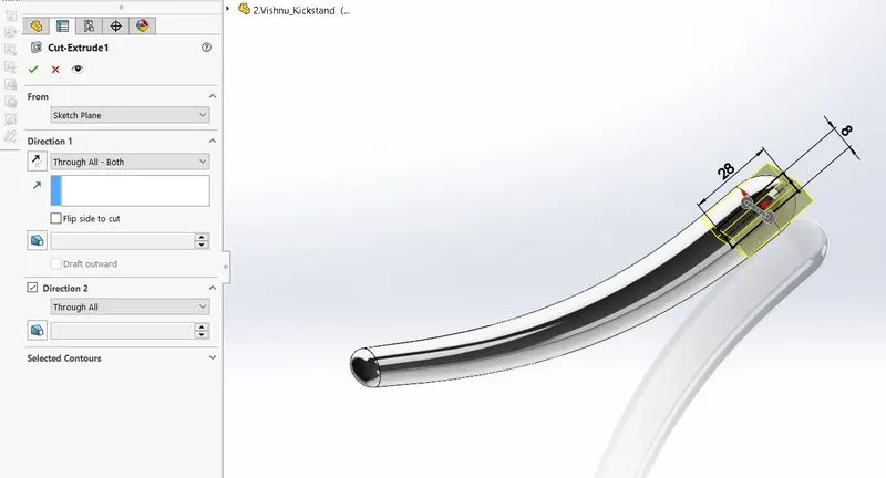
We use the Extrude Cut feature to cut or remove material from the 3-D model. Another sketch is used to define the shape of the cut. This feature is mainly used to create holes, channels, slots, etc. in the 3-D model.
The split feature used to split a body into multiple pieces by projecting an entity into the body. Sketch feature is used to define the entity which is used to split the model. The split feature also provides us with an option to either keep the split parts of the body or consume the selected parts.
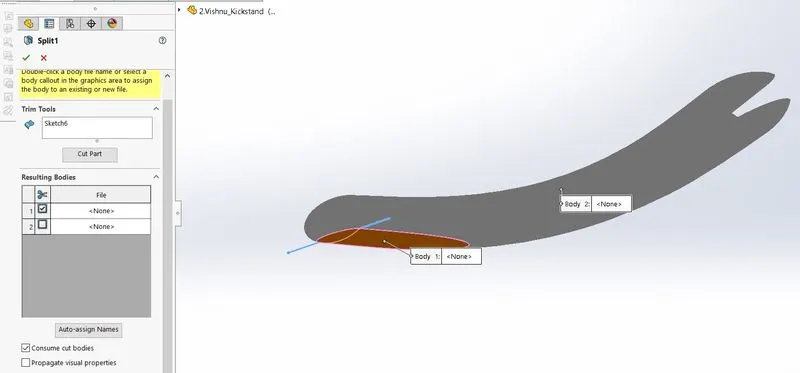
Using the Extrude Boss/Base feature, we can create a connecting rod for the kickstand. Again we use the sketch feature to define the shape of the extrude.
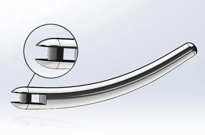
Using the Fillet feature, Edges can be rounded with an appropriate radius as shown in the figure below.
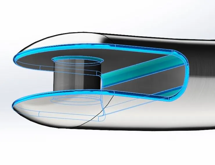
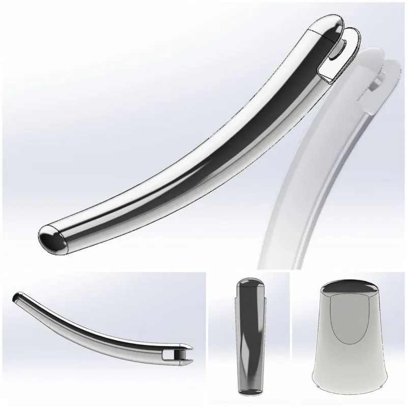
Finally using the Appearance feature, the Chrome material is applied to the model.
3.Front Fender
Features used:
- Sketch
- Revolve
- Split
- Fillet
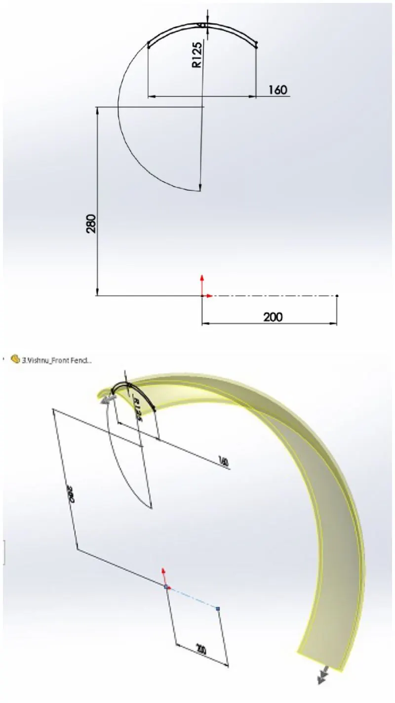
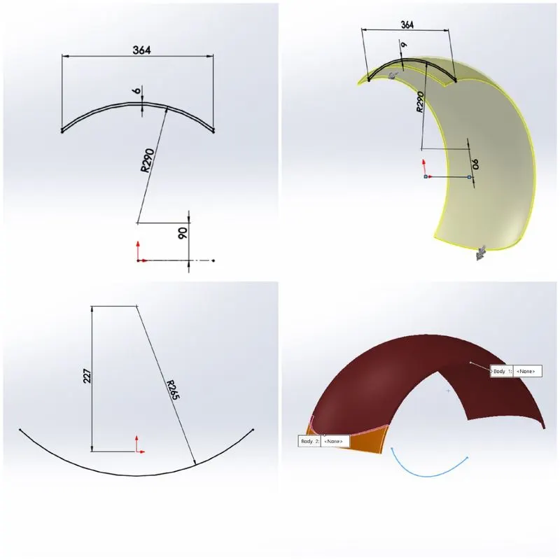
Initially, the 2-D sketch of the sectional profile of the fender is drawn using the Sketch feature. This Sketch is revolved along 5 degrees in direction 1 and 130 degrees in direction 2 using the Revolve feature.
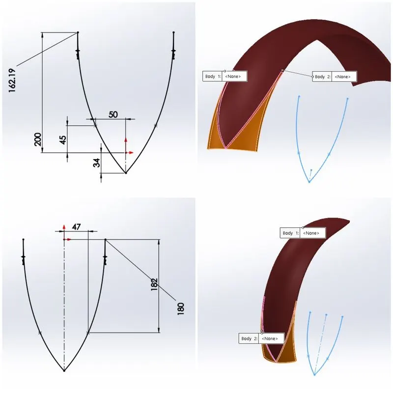
The Split feature is used to create the pointy shape at the end of the fenders. The sketch of the profile is made in the sketch feature to define the shape of the split, the unwanted part is deleted using the consume body option.
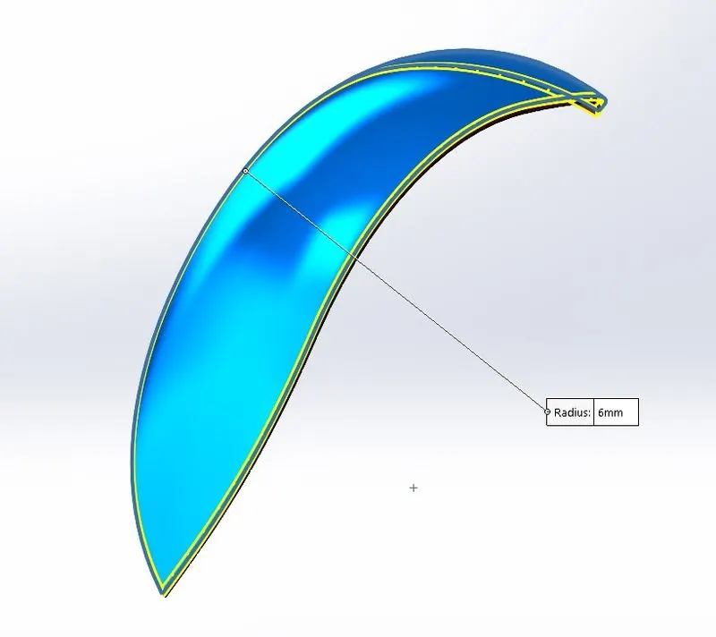
The Fillet feature is used to round the sharp edges of the fender. Instead of selecting each edge to be rounded, we can make use of the face selection feature available in SolidWorks, which allows us to select all the edges surrounding the selected face in a single click.
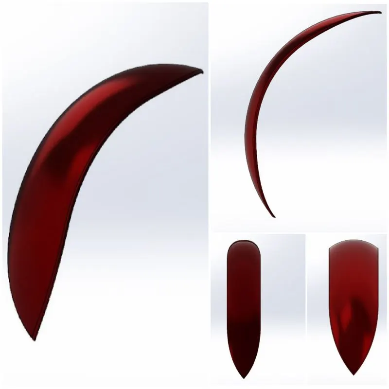
Finally, using the Appearance feature an appropriate material can be added to the fender for better visual aspects.
4.Front Fender
Features used:
- Sketch
- Revolve
- Split
- Fillet
- Shell
Using the Sketch feature, the sectional profile of the rear fender is drawn. This Sketch is revolved along 10 degrees in direction 1 and 140 degrees in direction 2 using the Revolve feature. The split feature is used to cut the end of the rear fender in the desired shape. A 2-D sketch of the cutting profile is made using the Sketch feature. The unwanted part is deleted using the consume body option available in the split feature.
The Fillet feature is used to round the corners and sharp edges of the rear fender. The Shell feature is used to hollow out a part, leaves open the faces you select, and creates thin-walled features on the remaining faces. Here, we select the inner face and apply a thickness of 4mm.
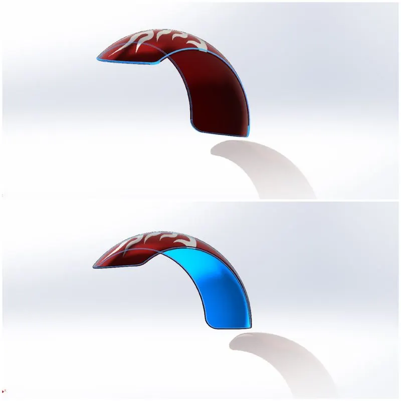
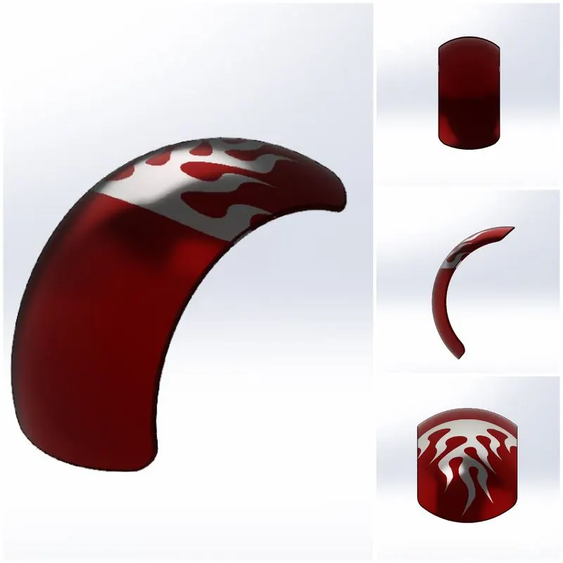
Finally, appropriate material is applied to the fender using the Appearance feature.
5.Chain
Features used:
- Sketch
- Blocks
- Extrude Boss/Base
- Curve driven Pattern
- Fillet
- Mirror
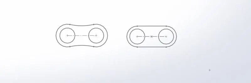
Initially, the 2-D profile of the chain is drawn using the Sketch feature as shown in the Figure.
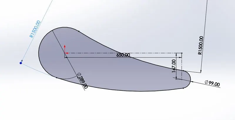
To create the outer chain link and inner chain link, we use the Block feature. Block feature helps us to save a lot of time as the same sketch are used multiple times and it also reduces the no. of sketches created thus making our part-tree less complicated.
Extrude Boss/Base feature is used to provide the 2-D sketch with its 3rd dimension. Sharp edges are then rounded using the Fillet feature.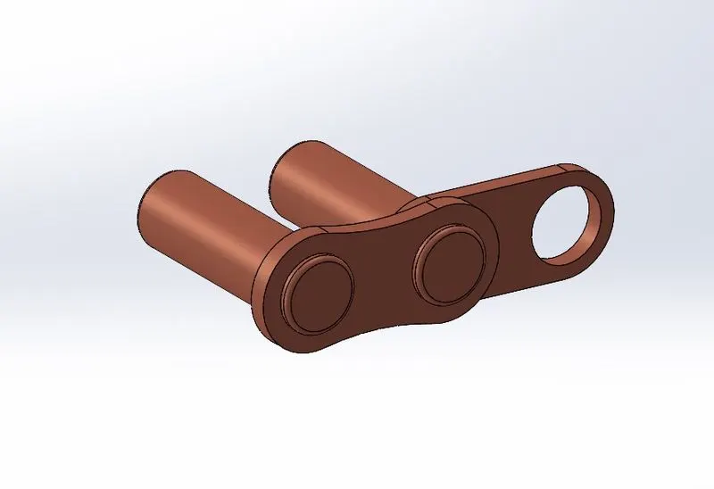
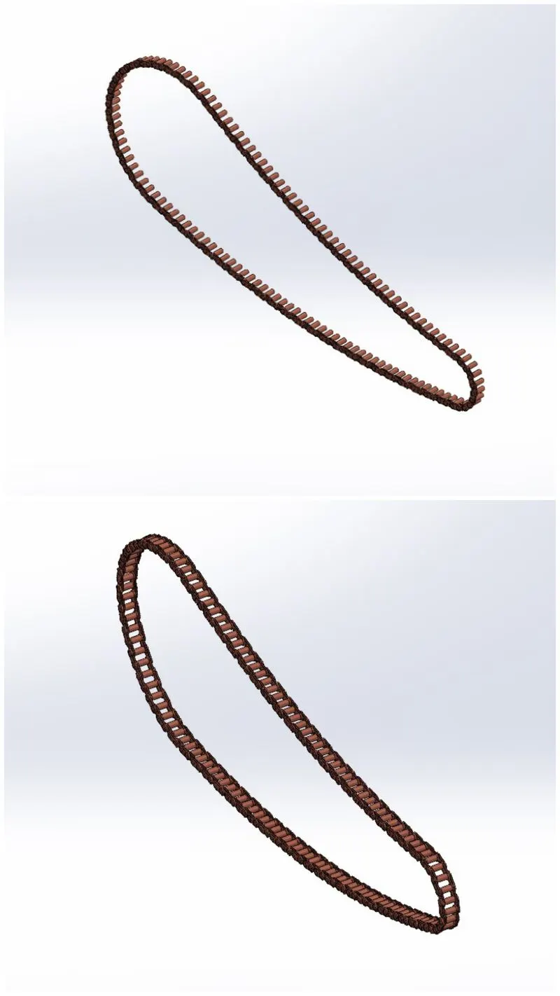
We use the Curve driven pattern feature to create the chain-links along the profile we created in the first sketch. The extruded features are selected as the pattern entity and the sketch-1 is selected as the Curve or Path to be followed. All the outer chain-links and inner chain-links are mirrored about the Mid-Plane using the Mirror Feature to complete the model.
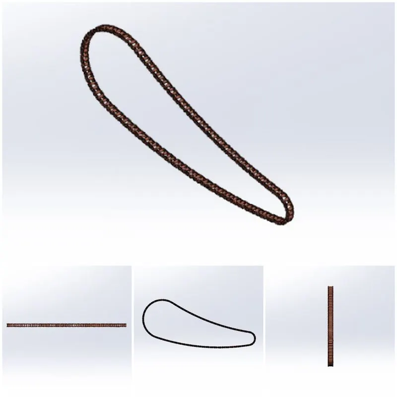
Finally using the Appearance feature, appropriate material is added to the model.
6.Fuel Tank
Features used:
- Sketch
- Extrude Boss/Base
- Fillet
- Shell
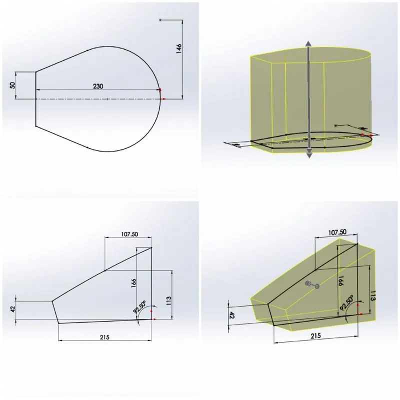
In the modelling of complex shapes, we can use multiple 2-D sketches in appropriate planes to define the shape of the model. In this particular case, we use 2 sketches to define the shape of our model. The sketches as shown in the figure below. These two sketches are extruded using Extrude Boss/Base feature.
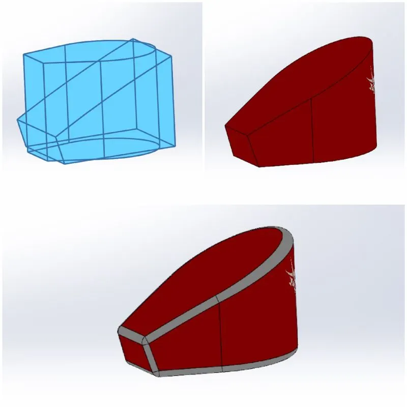
These two extruded bodies are then combines using the Combine feature. The combine feature provides you with 3 options to perform 1. Add 2.Subtract 3.Common. Here we use the Common option to create our model. Appropriate fillets are given to sharp edges using the Fillet feature.
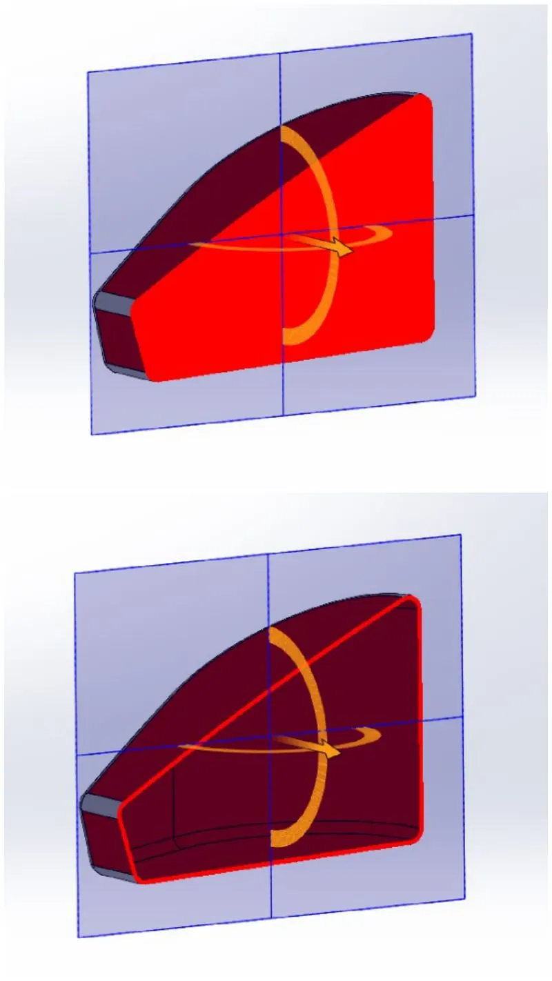
The Shell feature is used to hollow out a part and creates thin-walled features on the remaining faces. The thickness of the shell can be provided inside the shell feature.
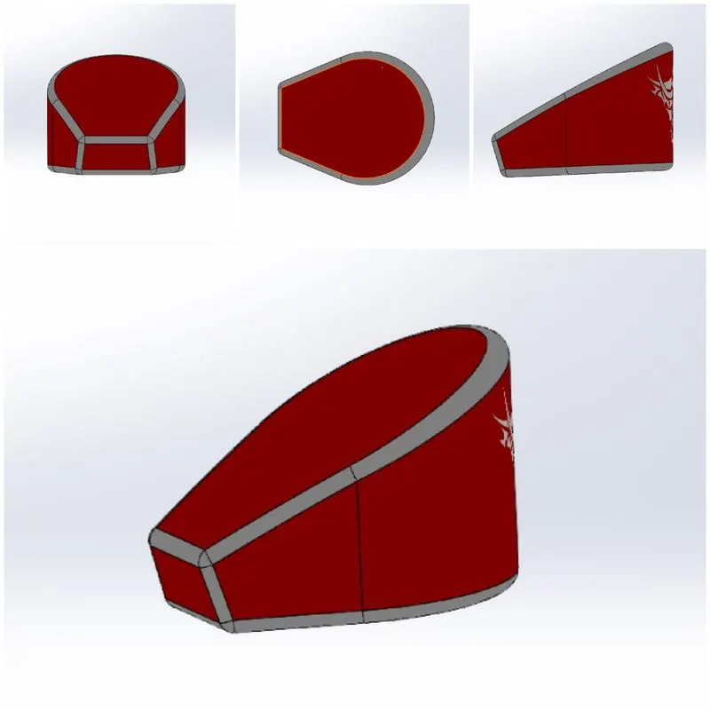
Finally using the Appearance feature, appropriate material is added to the model.
7.Pedal
Features used:
- Sketch
- Extrude Boss/Base
- Revolve
- Fillet
- Linear Pattern
- Chamfer
- Dome
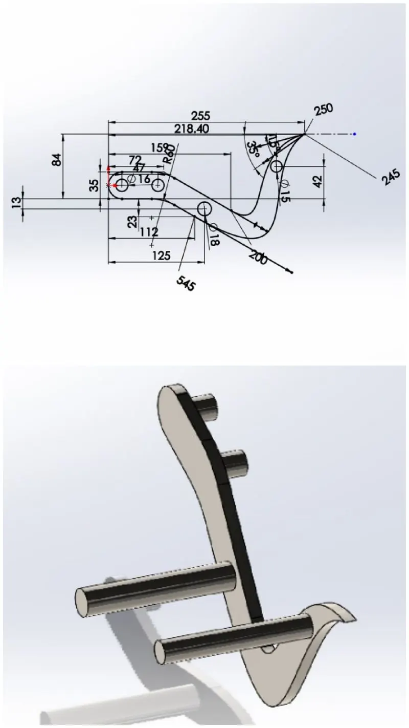
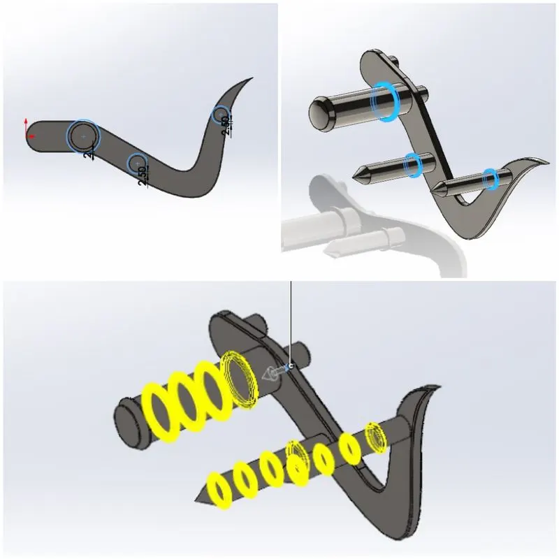
Using the Sketch feature, the 2-D profile of the pedal is drawn as shown in the figure below. The Sketch created is used to extrude using the Extrude feature to provide it with its 3rd dimension. Here the Extrude function is used twice with the same sketch to create the model as shown in the figure below. Parts of the same sketch are used each time using the select-contour option available in the Extrude feature.
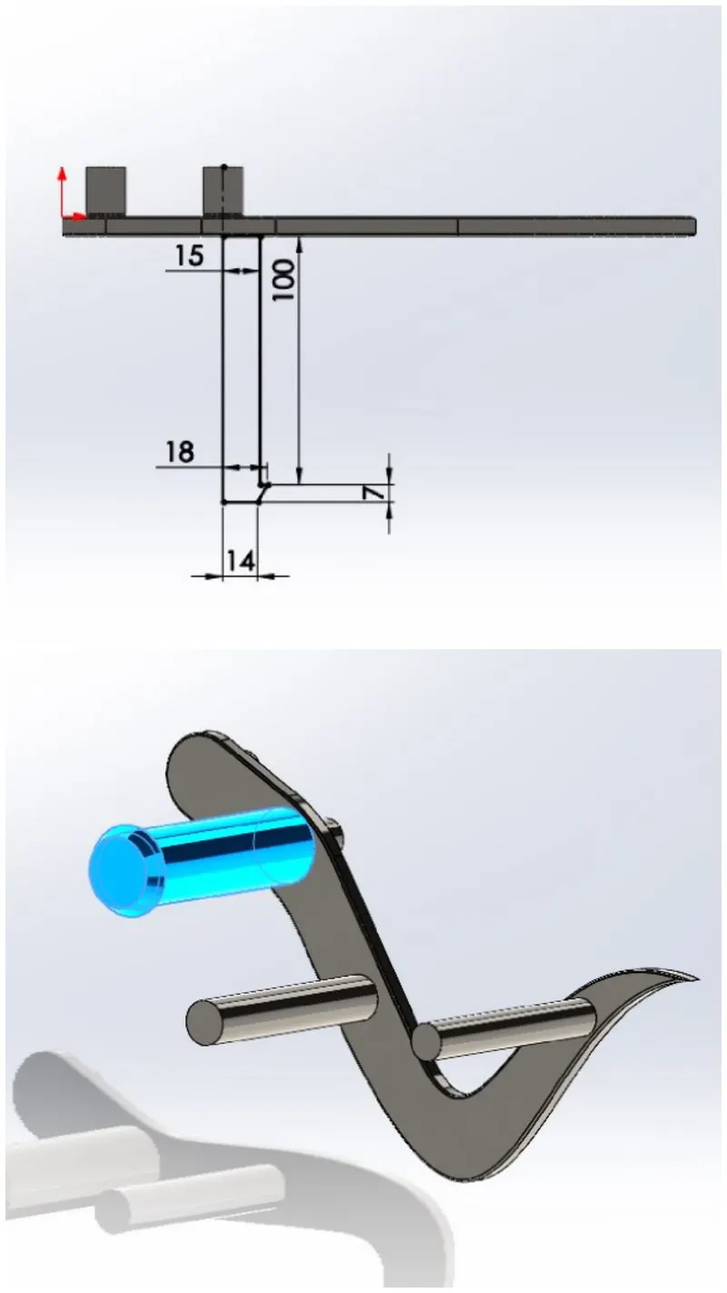
Another 2-D sketch is drawn as shown in the figure and is converted to 3-D using the Revolve feature.
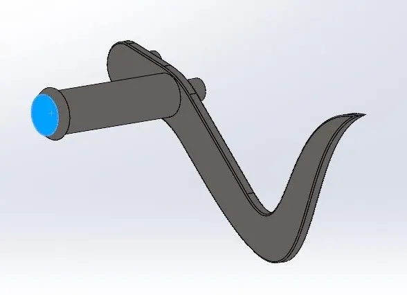
Using the Dome feature, a Dome can be created on the selected face and a height of 3 mm can be given to it.
Using the Chamfer feature, conical shapes can be achieved as shown in the figure. We select Asymmetric as chamfer parameter and the appropriate value is applied in the Distance 1 and Distance 2 section.
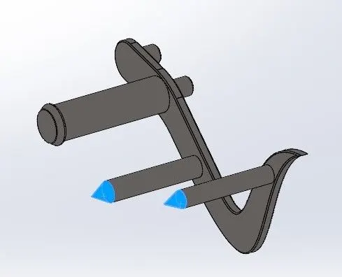
Another 2-D sketch is drawn using the offset feature, and the extruded using the extrude feature as shown in the figure. The newly extruded part is selected as the Pattern entity and Edge 1 is selected as the path. The spacing distance and the no. of entities can be added inside the Linear pattern feature.
The Fillet feature is used to round the sharp edges. All the sharp edges are selected and an appropriate fillet radius value is applied.
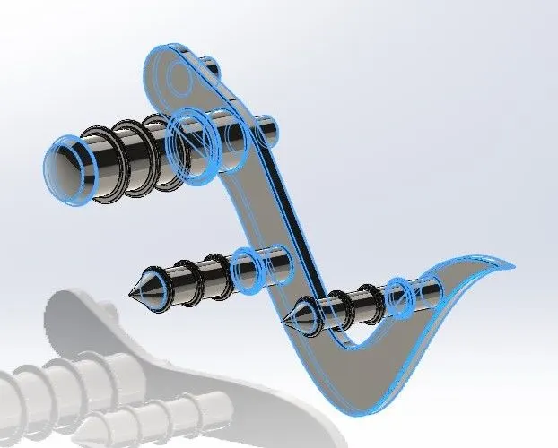
Finally using the Appearance feature, appropriate material is added to the model.
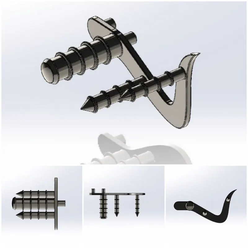
8.Front-Wheel
Features used:
- Sketch
- Extrude Boss/Base
- Extruded Cut
- Revolve
- Revolve cut
- Fillet
- Circular Pattern
- Chamfer
- Appearances
The front wheel can be modelled into 4 parts/bodies, 1. The Rim 2.Tyre 3.Disc Brake 4. Brake Calliper
The 2-D sectional profile of the rim is drawn using the Sketch feature and is converted to 3-D using the revolve feature.
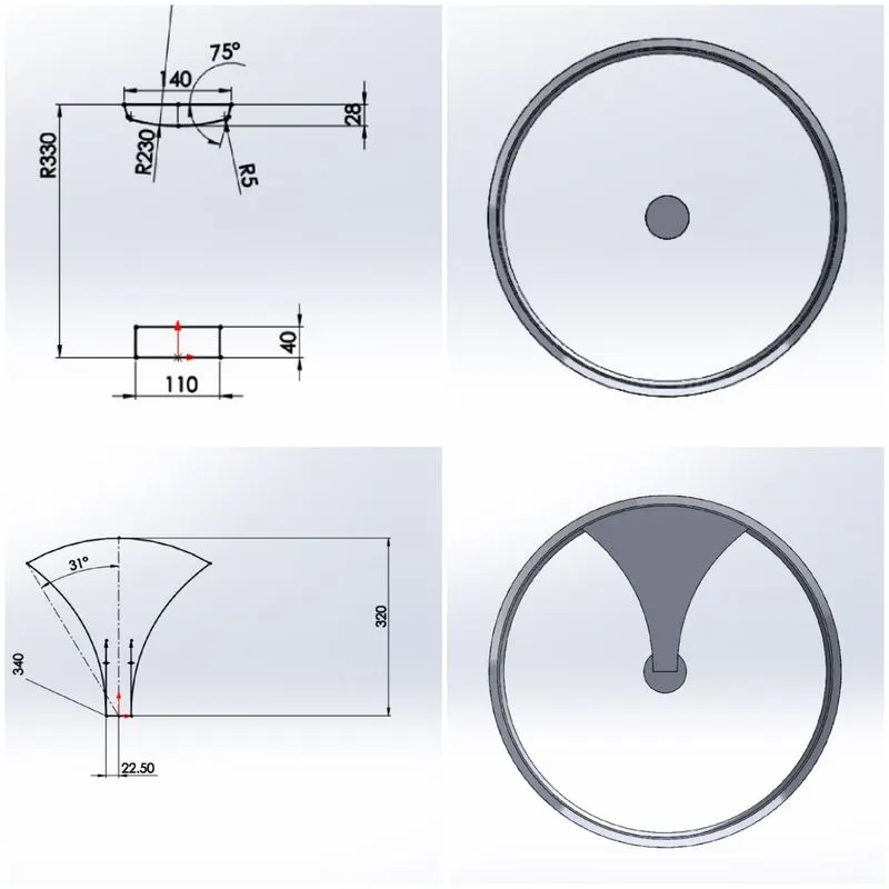 Similarly, The Sketch of the 2-D design pattern inside the rim is created and converted to 3-D using the Extrude Boss/Base feature. The curvature to the design pattern is given using the Revolve cut feature, the curvature profile is drawn and used in the Revolve cut feature and the radius of the rim is selected as the revolve path. The Fillet feature is used to round the sharp edges in the Model.
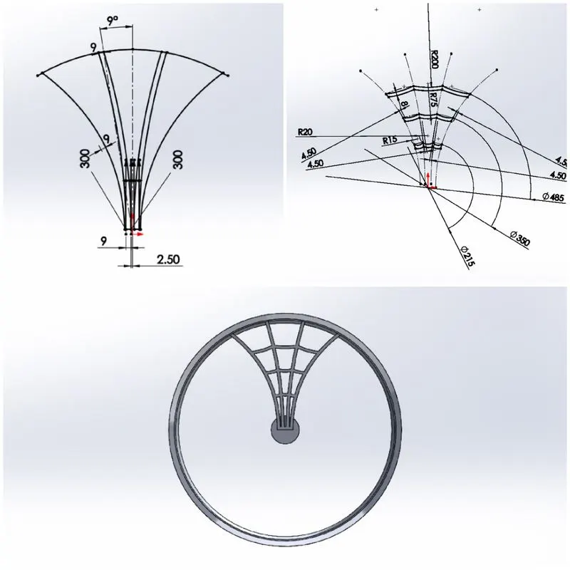
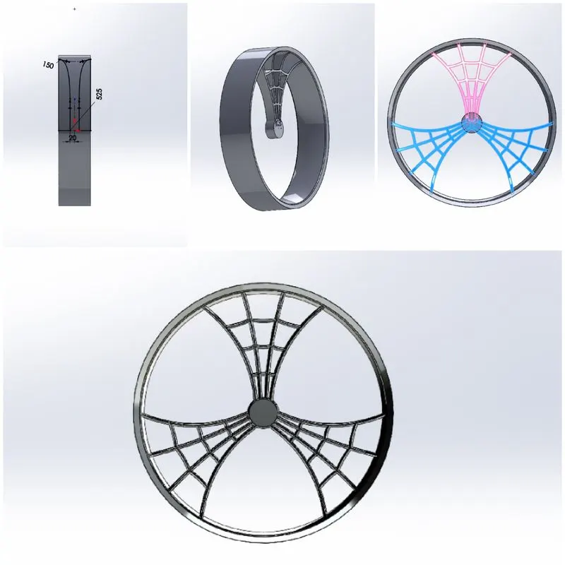
The created inner rim design feature is then patterned using the Circular pattern feature, the design feature to be patterned and the no. of instances to be created are selected, the equal spacing option is selected to create an equally spaced design pattern. The Combine feature is used to combine all the individual bodies into a single body.
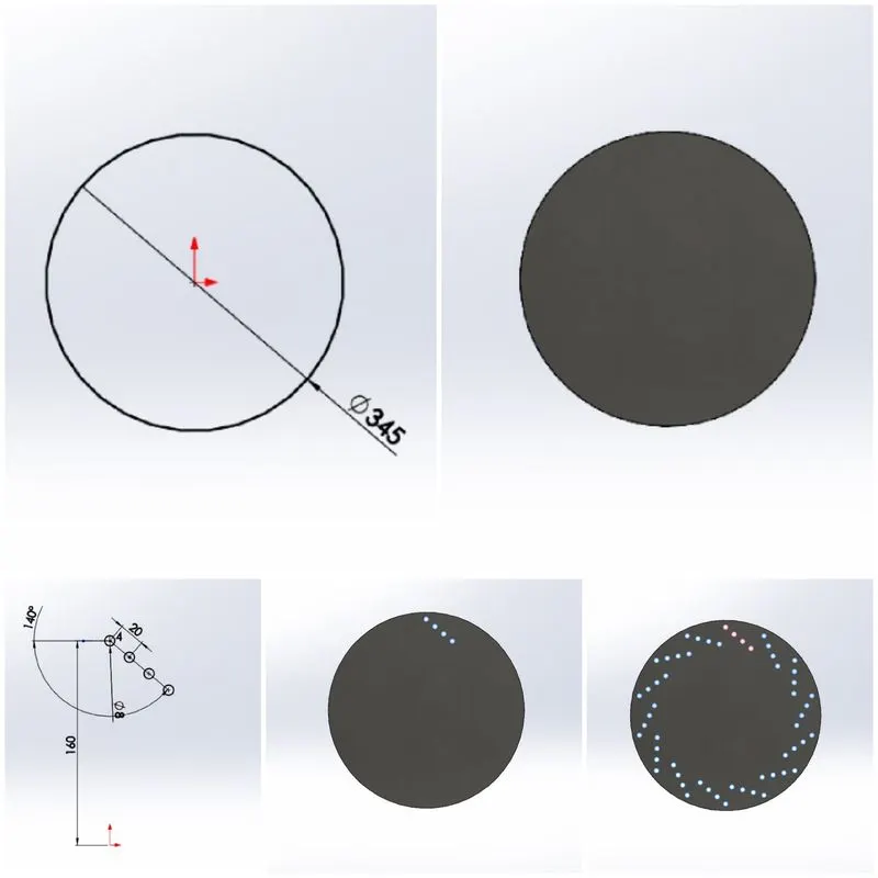
The 2-D sketch of the Disc Brake is drawn using the sketch feature and is then converted to 3-D using the Extrude Boss/Base feature. Another 2-D sketch of the design pattern is created and using the Extrude cut feature, the design is cut from the Disc brake as shown in the Figure. Using the Circular pattern feature, the design is patterned over the surface with equal spacing to complete the design.
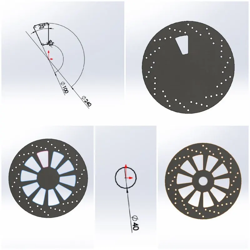
The profile of the Brake calliper is drawn in the form of a 2-D sketch and is extruded using the Extrude Boss/Base feature.
A chamfer is made on both sides of the calliper using the Chamfer feature and Fillets are added to all the sharp edges of the body using the Fillet feature.
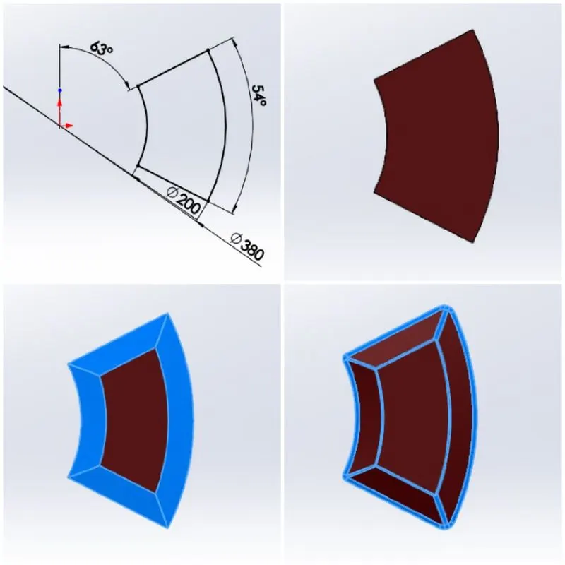
The sectional profile of the tyre is created using the Sketch feature, This is revolved using the Revolve feature to convert the sketch to a 3-D model.
The Design pattern to be created on the tyre is drawn as a 2-D sketch using the Sketch feature. Using the Extrude Boss/Base feature, the design pattern is extruded from the tyre. Fillets are added to round the sharp edges of the design pattern created using the Fillet feature.
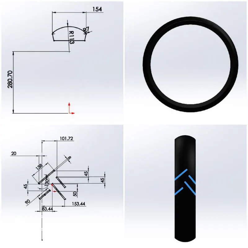
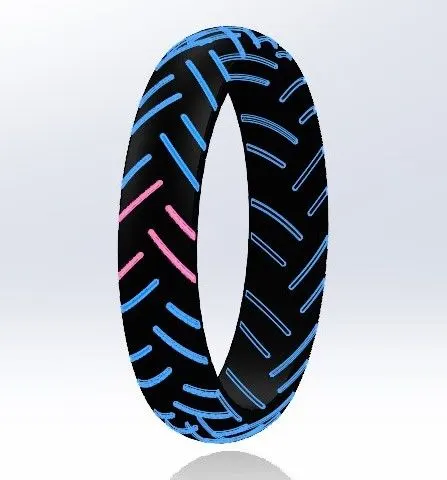
Using the Circular pattern feature, the tread design created is patterned all over the surface of the tyre with equal spacing as shown in the figure.
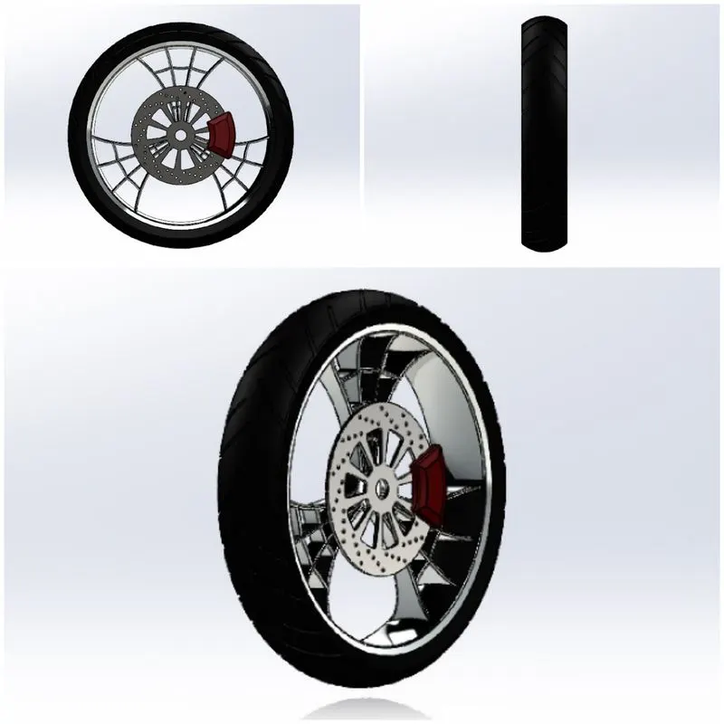
Finally using the Appearances feature, each part is applied with appropriate materials to complete the model.
9.Rear-Wheel
Features used:
- Sketch
- Extrude Boss/Base
- Extruded Cut
- Revolve
- Revolve cut
- Fillet
- Circular Pattern
- Chamfer
- Appearances
To create the Rear-Wheel, the same approach followed in the creation of the Front-wheel is applied here.
The Rear-wheel can be modelled into 5 parts/bodies, 1. The Rim 2.Tyre 3.Disc Brake 4. Brake Calliper 5.Sprocket
The 2-D sectional profile of the rim is drawn using the Sketch feature and is converted to 3-D using the revolve feature. The Sketch of the 2-D design pattern inside the rim is created and converted to 3-D using the Extrude Boss/Base feature.
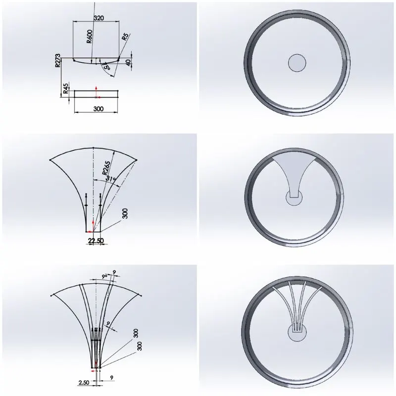
The curvature to the design pattern is given using the Revolve cut feature, the curvature profile is drawn and used in the Revolve cut feature and the radius of the rim is selected as the revolve path. The Fillet feature is used to round the sharp edges in the Model.
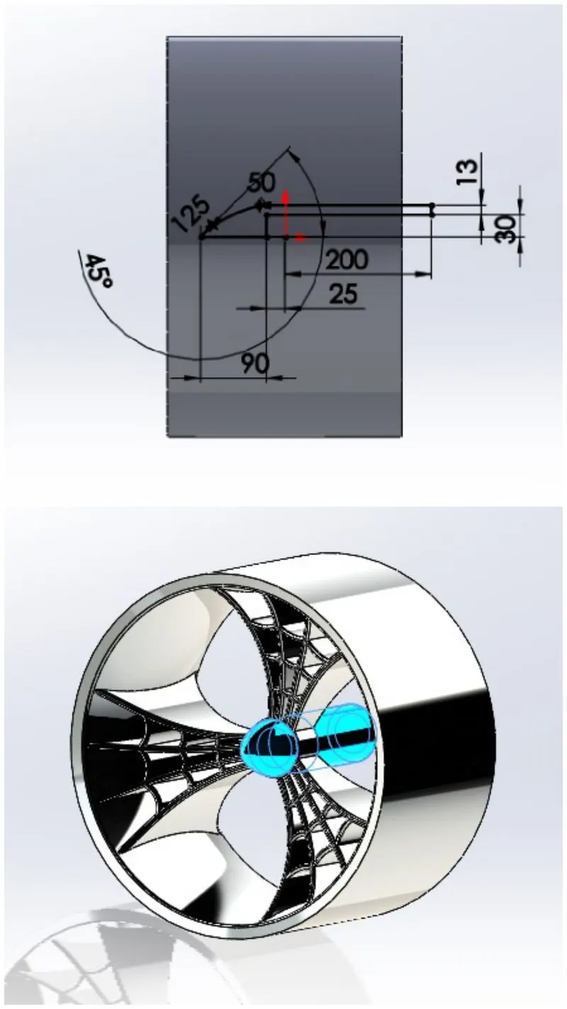
The created inner rim design feature is then patterned using the Circular pattern feature, the design feature to be patterned and the no. of instances to be created are selected, the equal spacing option is selected to create an equally spaced design pattern. The Combine feature is used to combine all the individual bodies into a single body.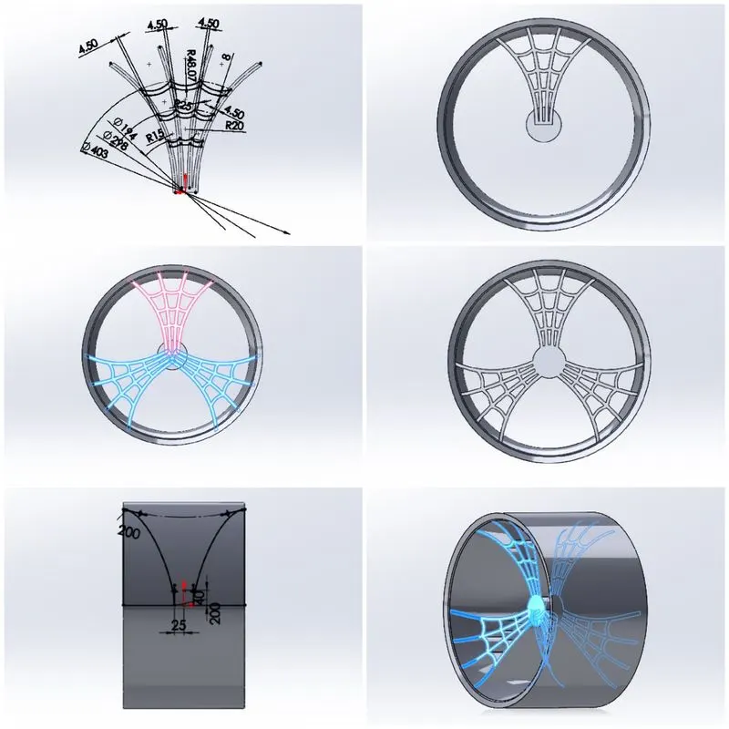
The centre-piece of the Rim is created using the Revolve feature. The profile to be revolved is Sketched using the sketch feature.
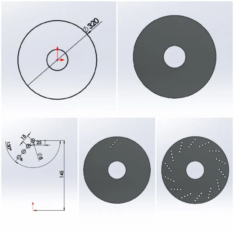
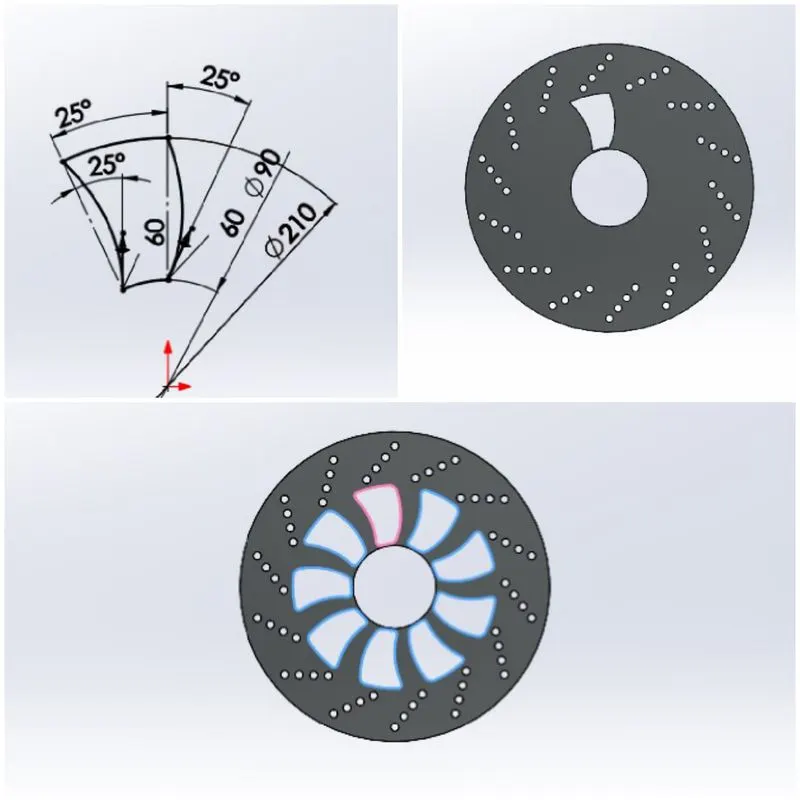
The 2-D sketch of the Disc Brake is drawn using the sketch feature and is then converted to 3-D using the Extrude Boss/Base feature. Another 2-D sketch of the design pattern is created and using the Extrude cut feature, the design is cut from the Disc brake as shown in the Figure. Using the Circular pattern feature, the design is patterned over the surface with equal spacing to complete the design.
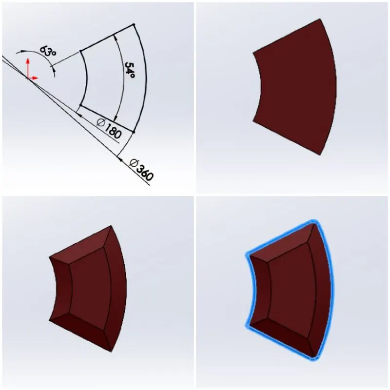
The profile of the Brake calliper is drawn in the form of a 2-D sketch and is extruded using the Extrude Boss/Base feature.
A chamfer is made on both sides of the calliper using the Chamfer feature and Fillets are added to all the sharp edges of the body using the Fillet feature.
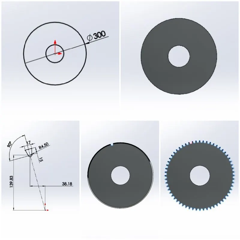
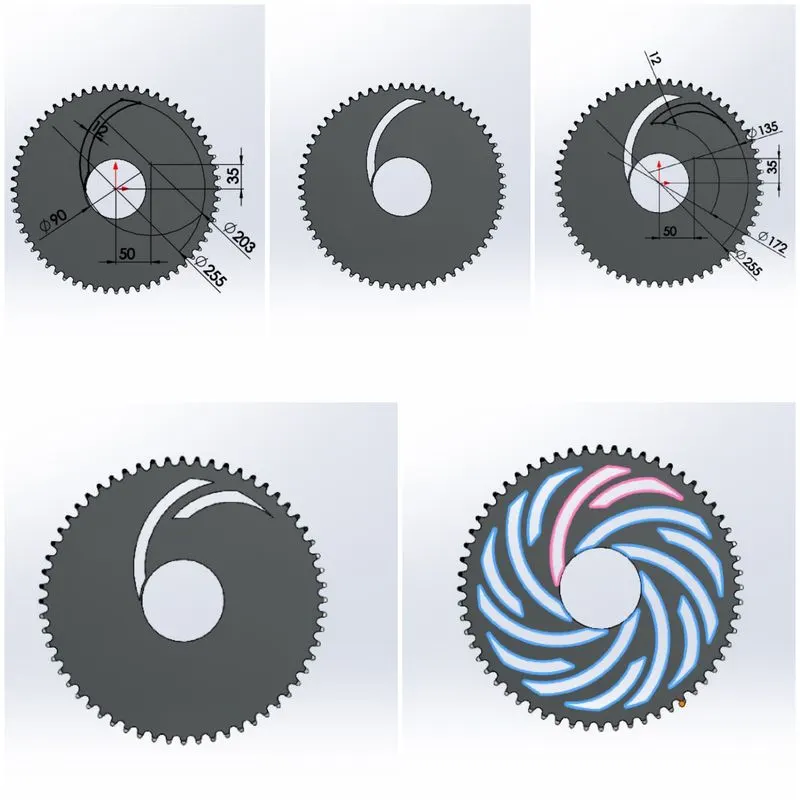
The 2-D sketch of the Sprocket is drawn using the sketch feature and is then converted to 3-D using the Extrude Boss/Base feature. Another 2-D sketch of the design pattern is created and using the Extrude cut feature, the design is cut from the Disc brake as shown in the Figure. Using the Circular pattern feature, the design is patterned over the surface with equal spacing to complete the design. The Fillet feature is used to round the sharp edges of the model.
The sectional profile of the tyre is created using the Sketch feature, This is revolved using the Revolve feature to convert the sketch to a 3-D model.
The Design pattern to be created on the tyre is drawn as a 2-D sketch using the Sketch feature. Using the Extrude Boss/Base feature, the design pattern is extruded from the tyre. Fillets are added to round the sharp edges of the design pattern created using the Fillet feature.
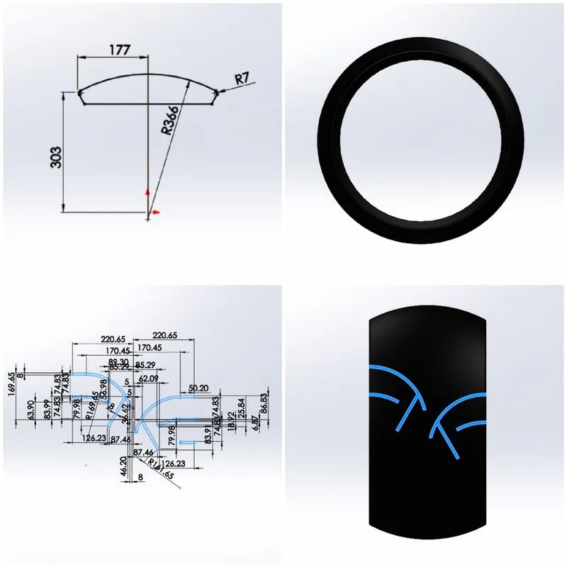
Using the Circular pattern feature, the tread design created is patterned all over the surface of the tyre with equal spacing as shown in the figure.
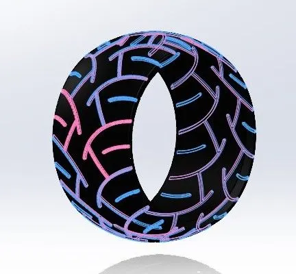
Finally using the Appearances feature, each part is applied with appropriate materials to complete the model.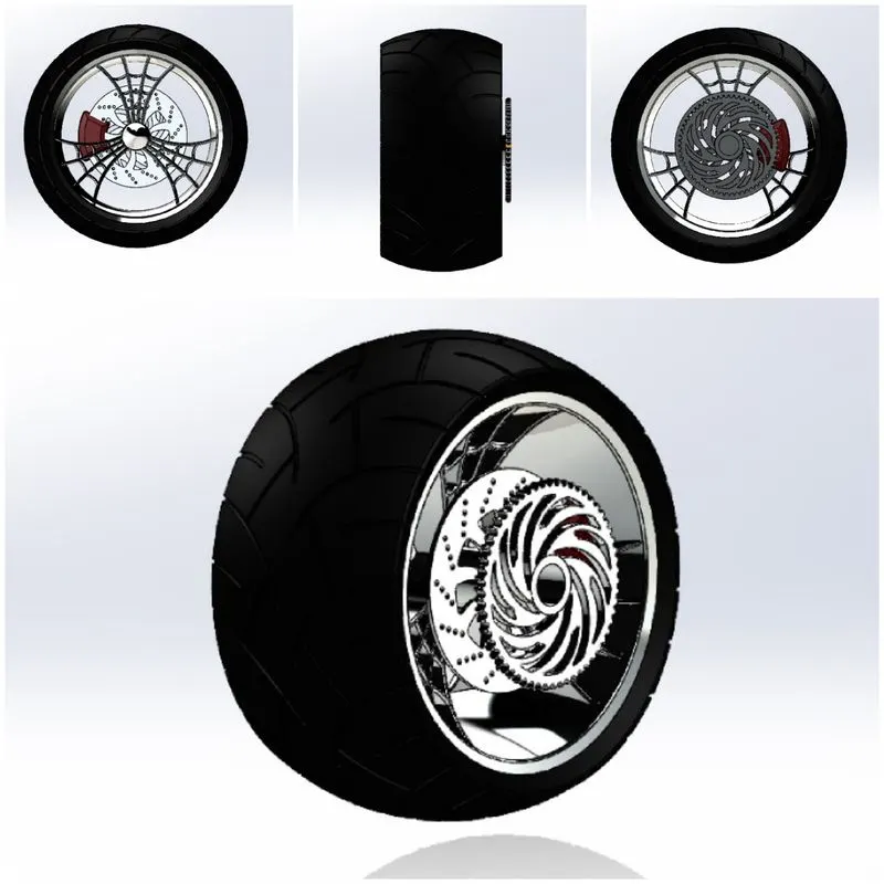
10.Front-Fork
Features used:
- Sketch
- Revolve
- Extrude Boss/Base
- Extruded Cut
- Revolve cut
- Fillet
- Projected curve
- Linear Pattern
- Sweep
- Mirror
- Combine
- Appearances
The modelling of the Front fork can be divided into 3 parts, 1.Fork 2.Headlight 3.Handle and 4.Brake lever.
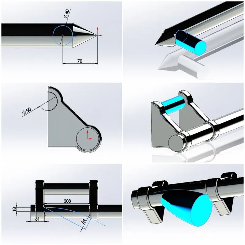
Using the Sketch feature, a 2-D sketch of the profile of the fork is drawn and then converted to 3-D using the Revolve feature. Another 2-D sketch of the profile of the Fork joint is drawn and converted to 3-D using the Extrude Boss/Base feature. Sharp edges are rounded using the Fillet feature. An additional copy of the fork joint is created at a certain distance using the Linear pattern feature as in the figure below.
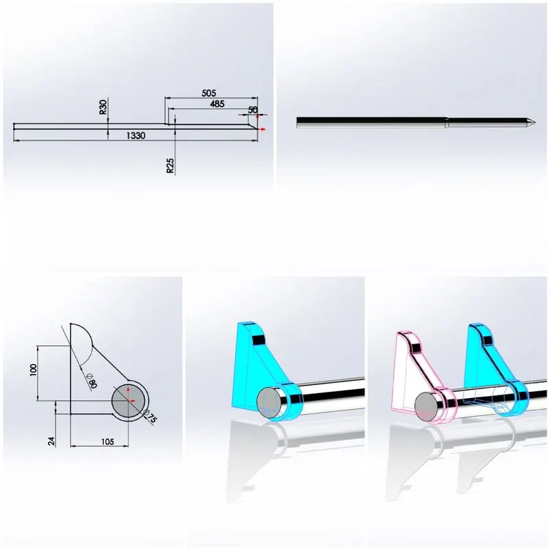
Similarly using the Sketch, Extrude Boss/Base, the rest of the Fork is completed and Using the Sketch and Revolve feature the basic shape of the Headlight is created.
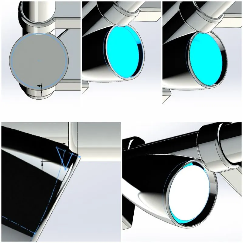
Using the Sketch and Extrude Cut feature, a cut is made on the surface of the headlight created.
Using the Dome feature, a curvature is given to the Headlight lens.
Using the Sketch and Revolve cut feature, the Headlight lens is given a depth as shown in the figure. U sign the fillet feature, fillets are added to round the sharp edges.
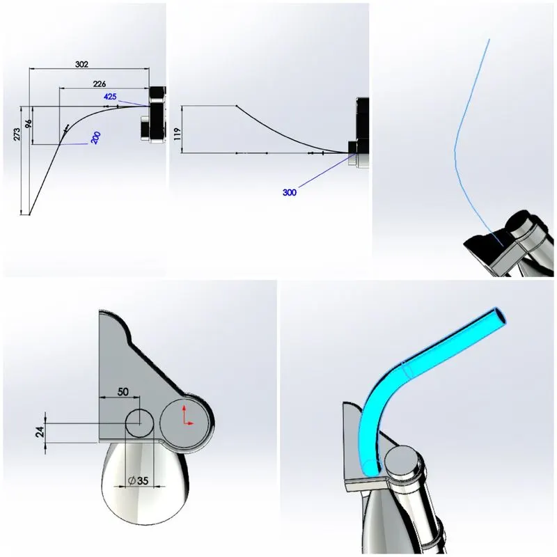
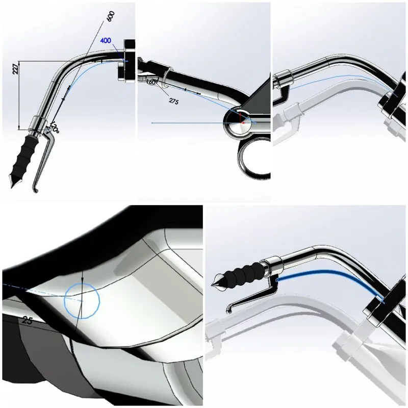
Using the Sketch and Projected Curve feature. The curvature axis of the Handlebar is created. 2-D sketch of the circular profile of the handlebar is created and using the Sweep feature, the circle is swept along the curvature axis created.
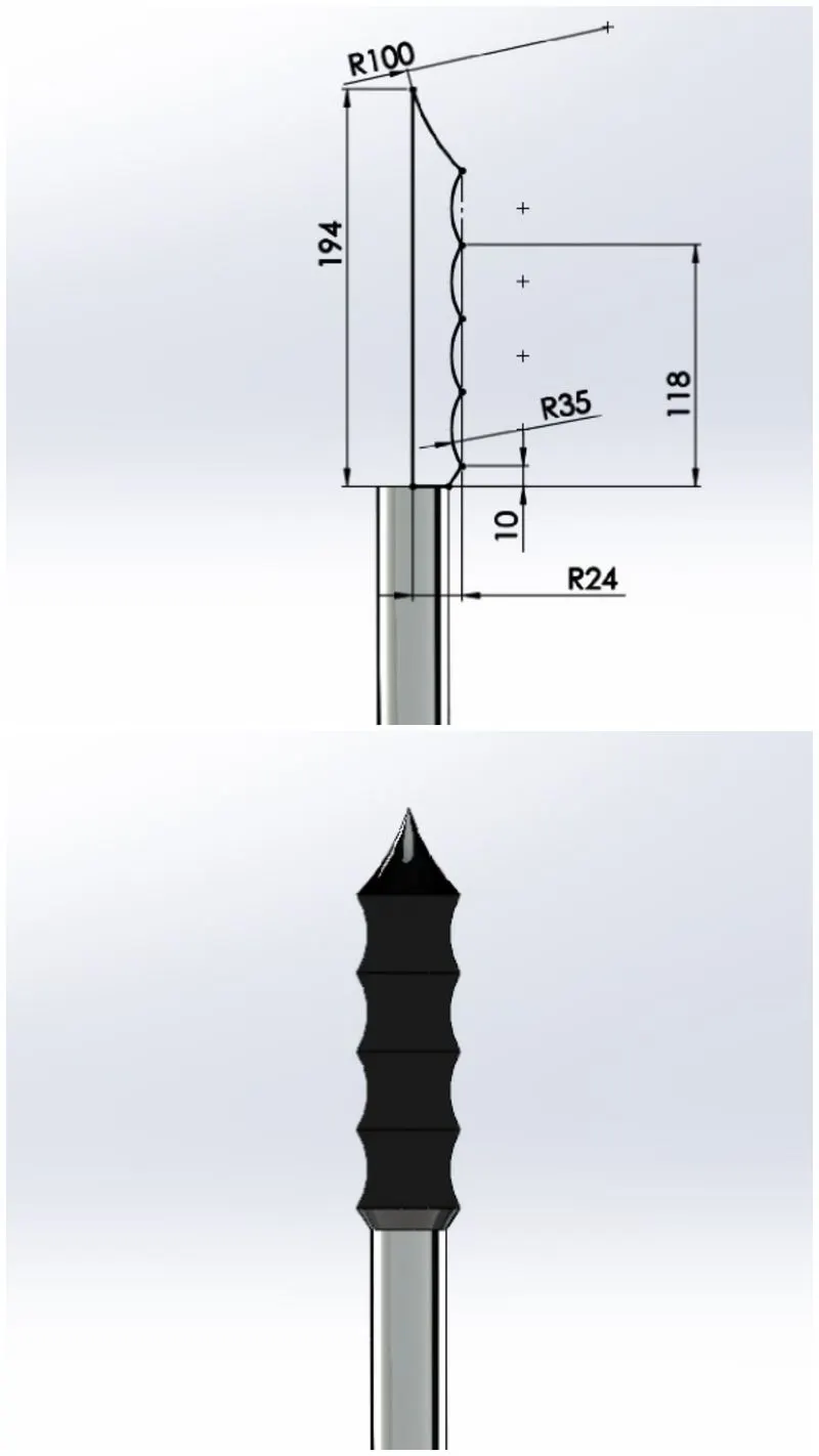
Using the Sketch and Revolve feature, the Grip of the handlebar is created.
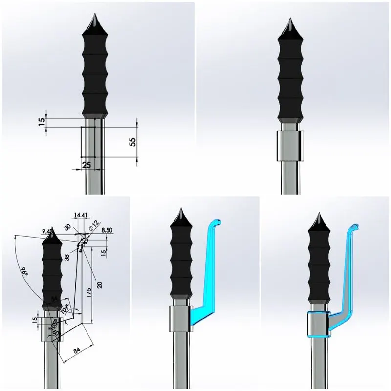
Using the Sketch and Revolve feature, the clamp of the Brake is created. Using the Sketch and Extrude Boss/Base feature, The Brake lever is created and sharp edges are rounded using the Fillet feature.
Using the Sketch and Projected Curve feature, the axis of the Brake cable is created. The circular profile of the cable is drawn using the Sketch feature and Using the Sweep feature, the circular profile is swept along the cable axis to create the Brake cable.
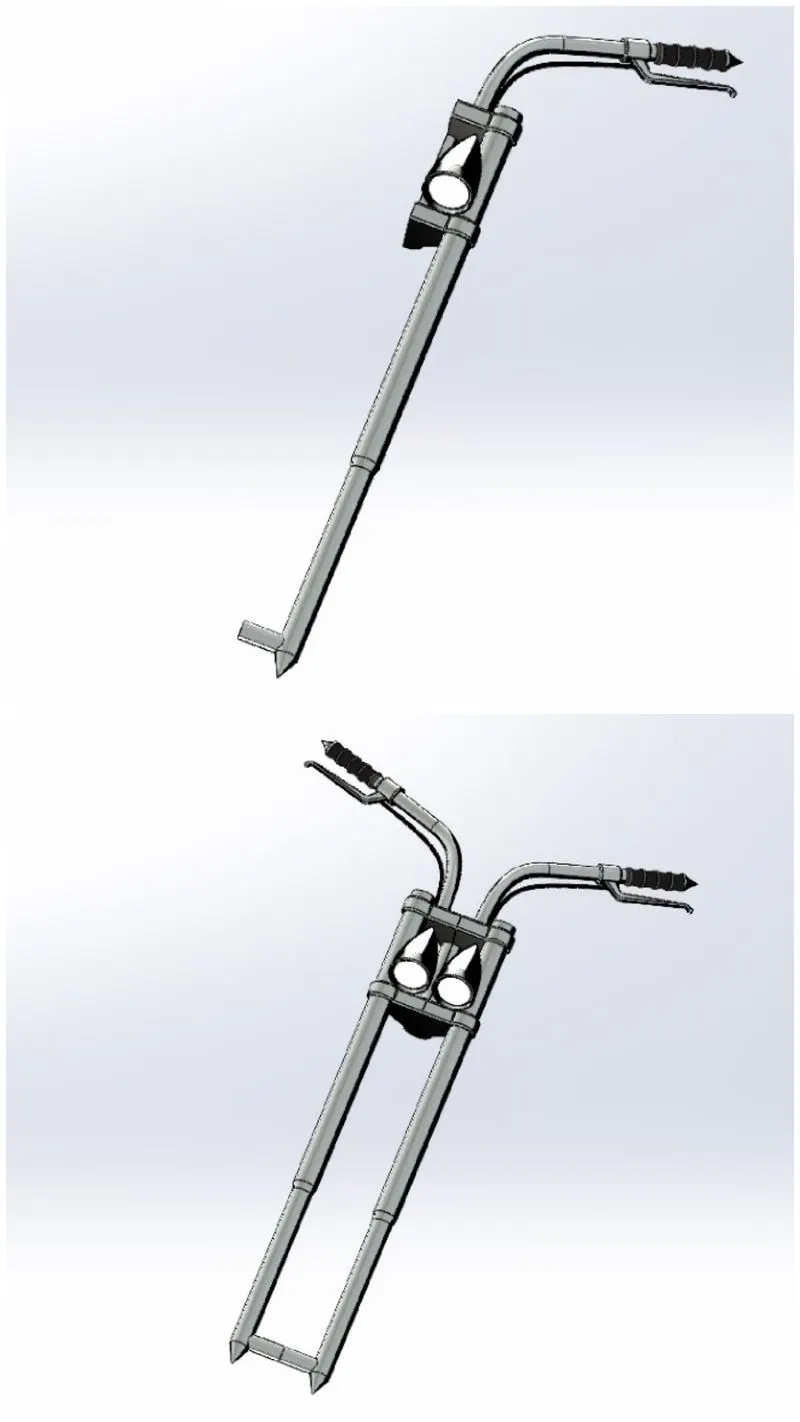
Using the Mirror feature, all the created models are mirrored about the centre to create the complete model. Using the Combine feature, the mirrored part is joined together with the created part to finish the model.
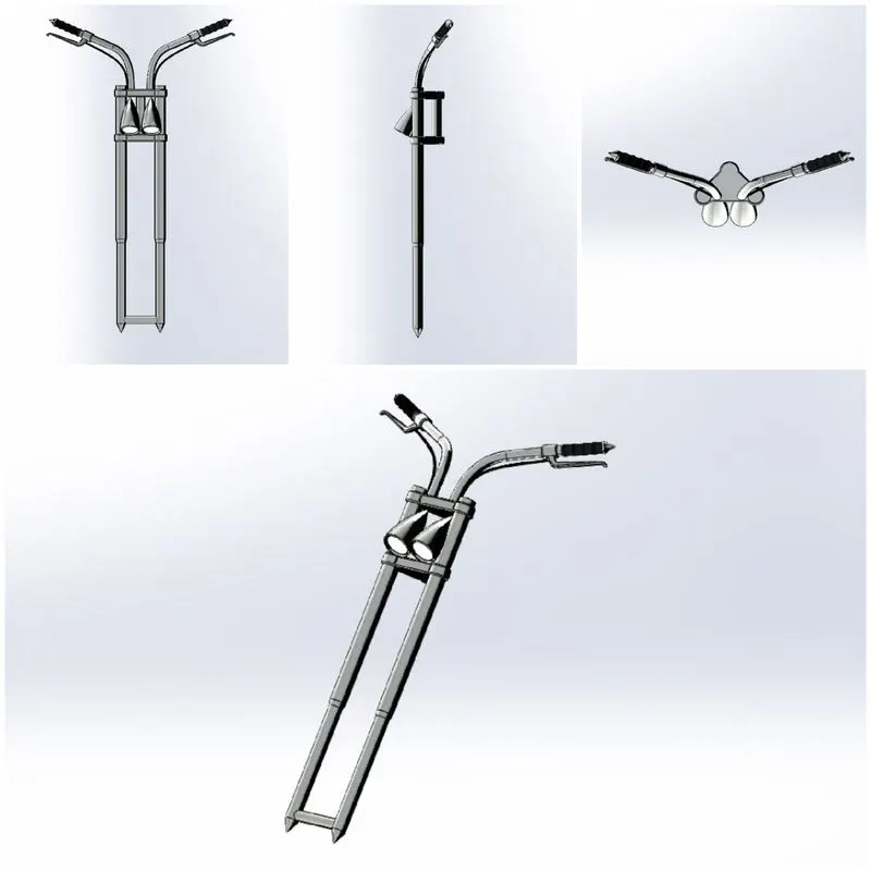
Using the Appearance feature, appropriate materials are applied to the model.
11.Chassis
Features used:
- Sketch
- Projected Curve
- Sweep
- Mirror
- Extrude Boss/Base
- Extruded Cut
- Split
- Revolve
- Fillet
- Chamfer
- Combine
- Appearances
Using the Sketch and Projected Curve feature, the 3-D curvature of the axis is drawn. Using the Sketch feature the circular profile of the tube is created and is swept along the 3-D axis of the curvature created using the Sweep feature.
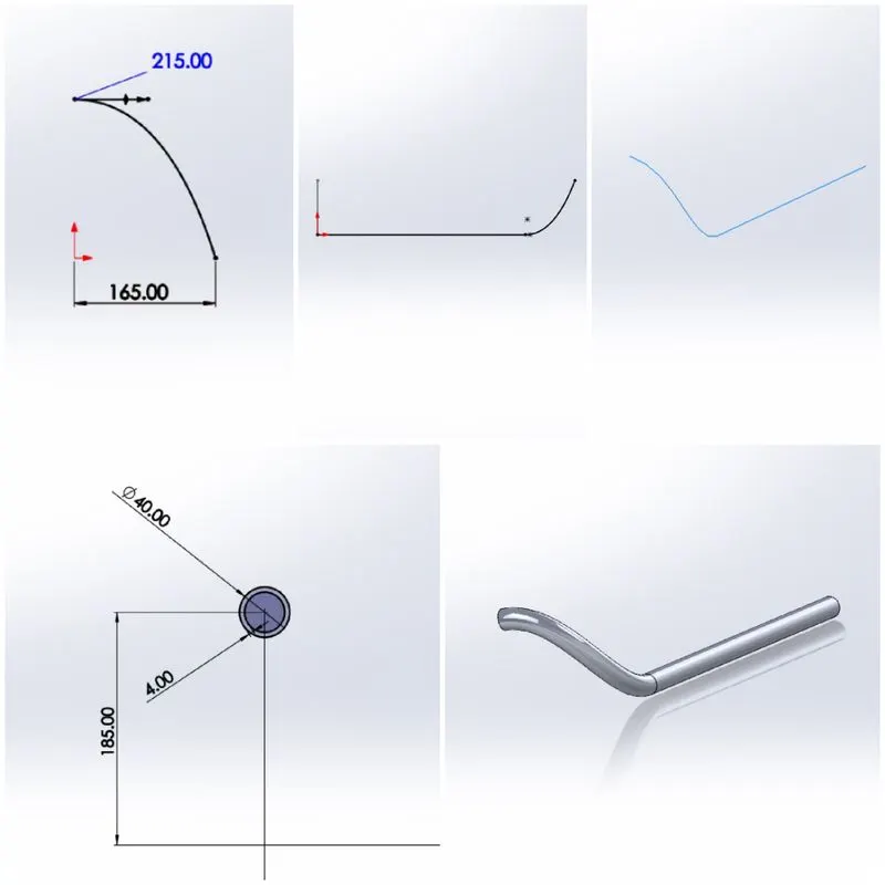
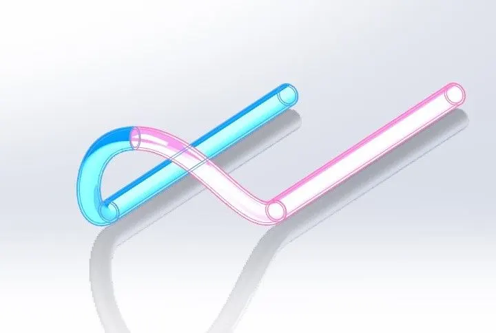
The created feature is mirrored to the other side using the Mirror feature. The Merge option is enabled to join the two separate entities into a single entity.
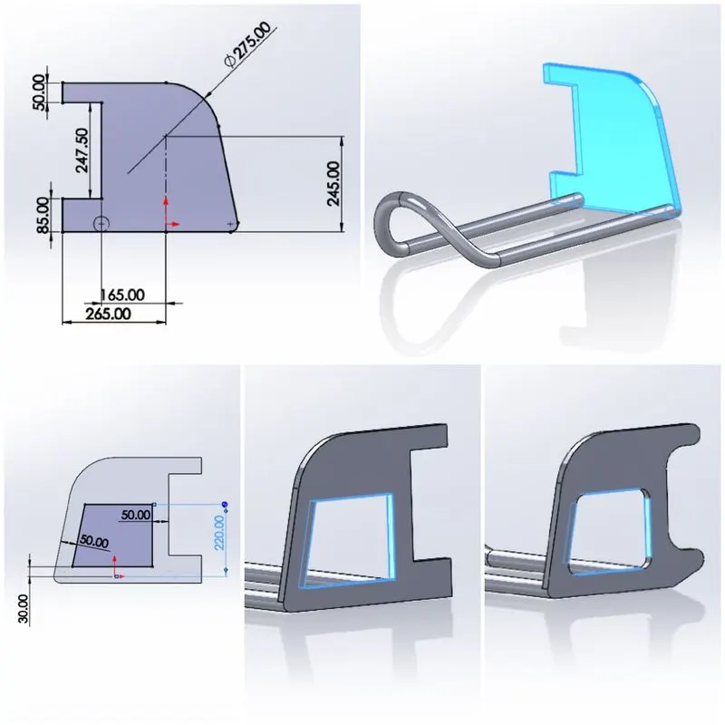
Using the Sketch and Extrude Boss/Base feature, the part of the Chassis is created as shown in the figure below. The Sketch and the Extrude Cut feature is used to create cut as shown in the figure below. The Fillet feature is used to round the sharp corners of the cut created.
Using the Sketch and Sweep feature, the tubes of the chassis are created as shown in the figure below.
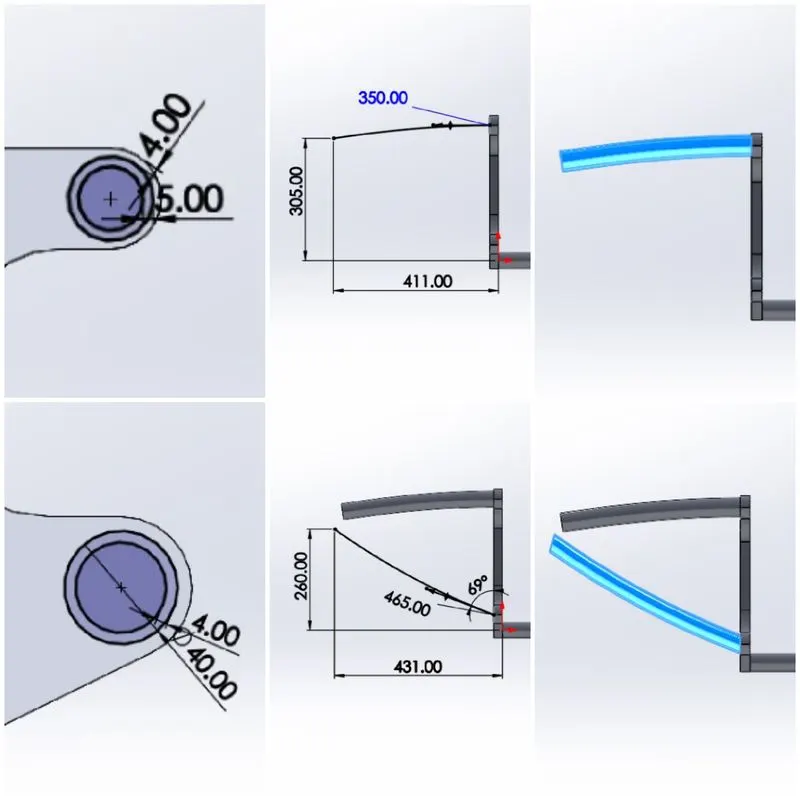
Using the Sketch and Extrude Boss/Base feature, the parts of the chassis are created as shown in the figure below.
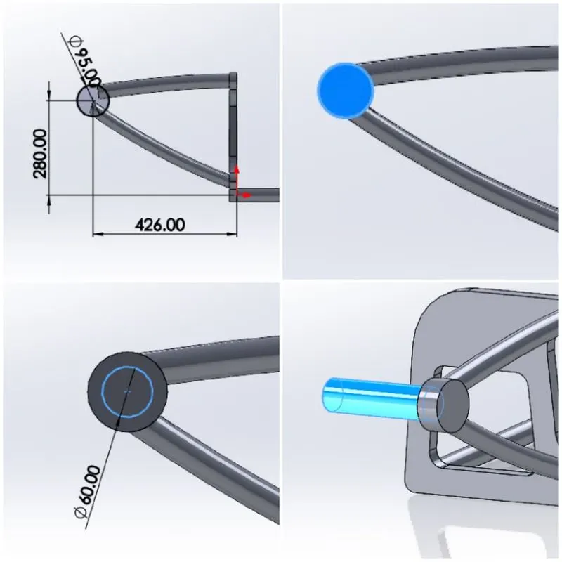
Using the Sketch and Sweep feature, the tubes of the chassis are created as shown in the figure below.
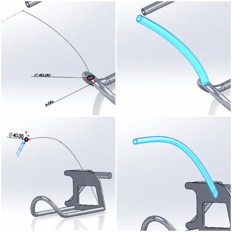
Using the Sketch and the Revolve feature, the tube where Front Fork is clamped is created.
Using the Sketch and the Extrude Boss/Base feature, the part where the Pedals of the chopper are clamped is created. Similarly, the base where the engine is mounted is created using the same method.
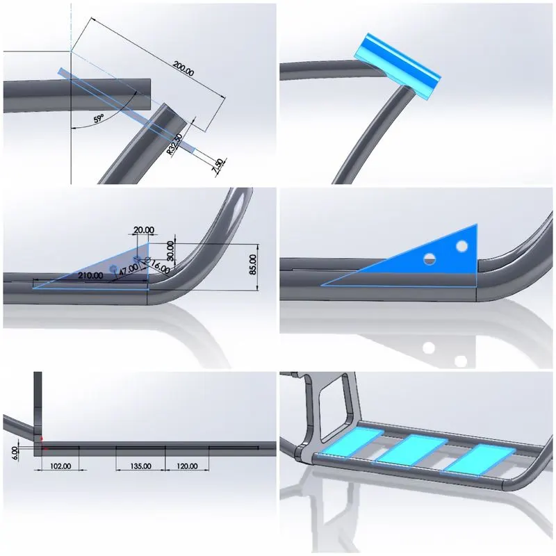
Using the Fillet feature, the sharp corners of the part where the pedals are clamped is rounded and the part is mirrored to the other side using the Mirror feature.
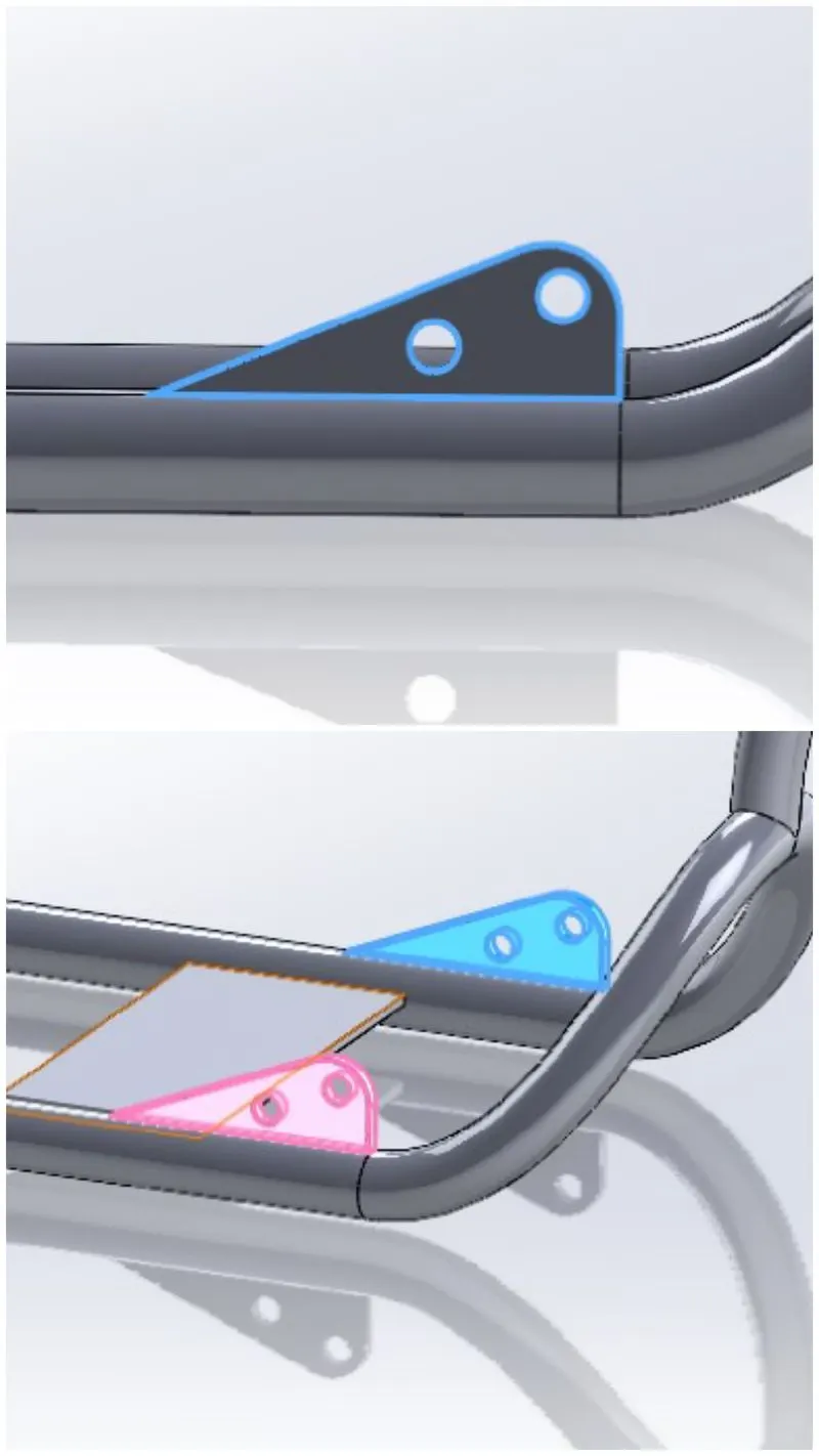
Using the Sketch and the Extrude Boss/Base feature, the part where the Kickstand of the chopper is clamped is created.
Using the Fillet feature, the sharp corners are rounded and the clamping hole is created using the Sketch and Extrude Cut feature.
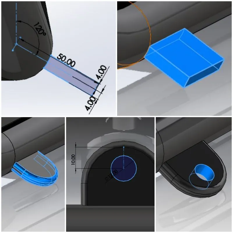
All the part are combined into a single body using the Combine feature. Finally, appropriate material is added to the chassis using the Appearance feature.
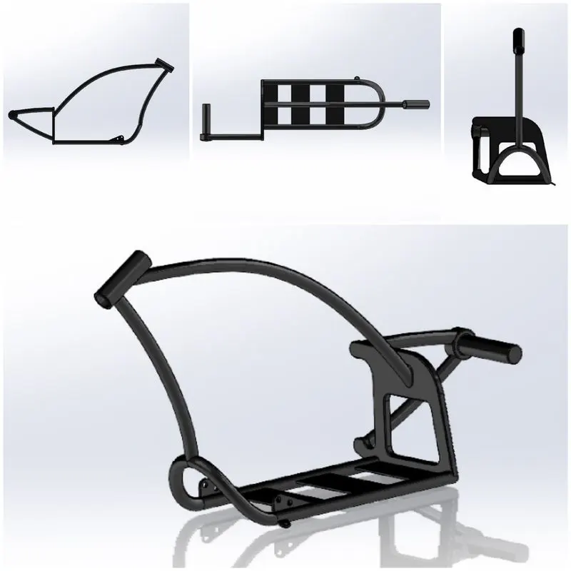
12.Engine
Features used:
- Sketch
- Projected Curve
- Sweep
- Mirror
- Extrude Boss/Base
- Extruded Cut
- Split
- Revolve
- Fillet
- Chamfer
- Combine
- Appearances
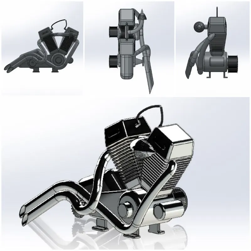
Using the Sketch and Extrude Boss/Base feature, the basic shape of the engine is created as shown in fig. below.
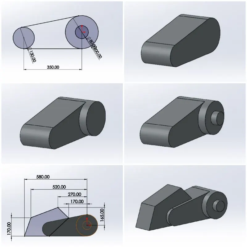
Using the Fillet feature, the sharp edges are rounded. Then using the Sketch and Revolve feature, the transmission pulleys are created as shown in the figure below.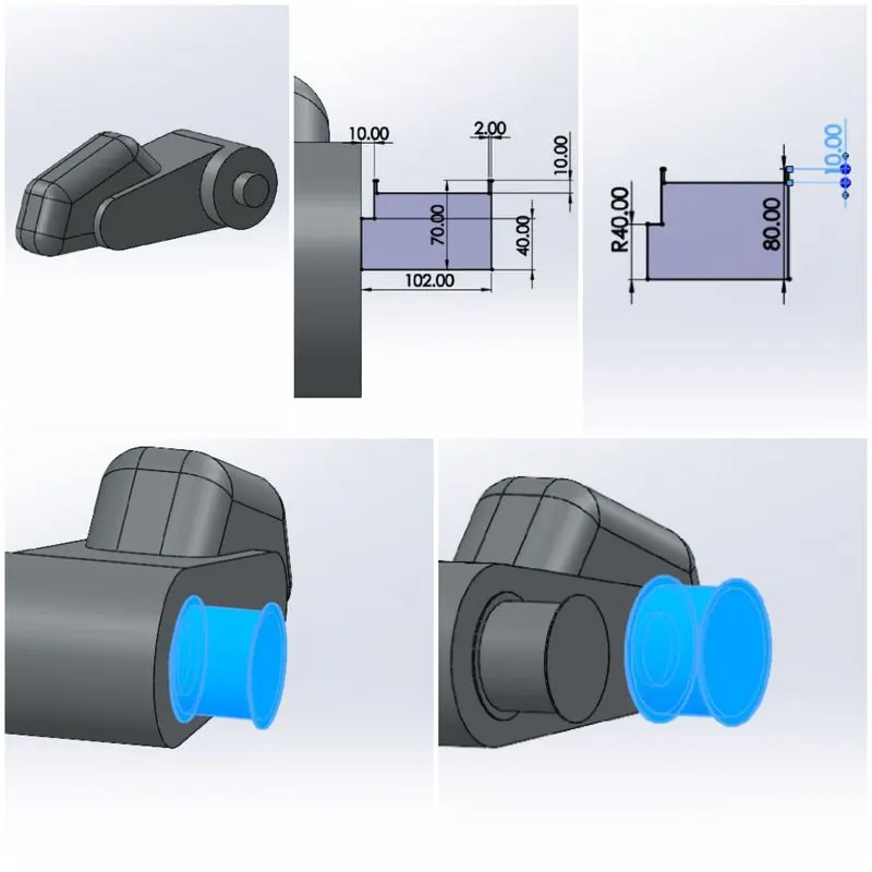
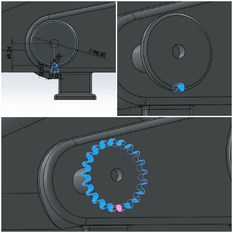
Using the Sketch and Extrude feature, the gear tooth is created and then the gear teeth are patterned using the Circular pattern feature.
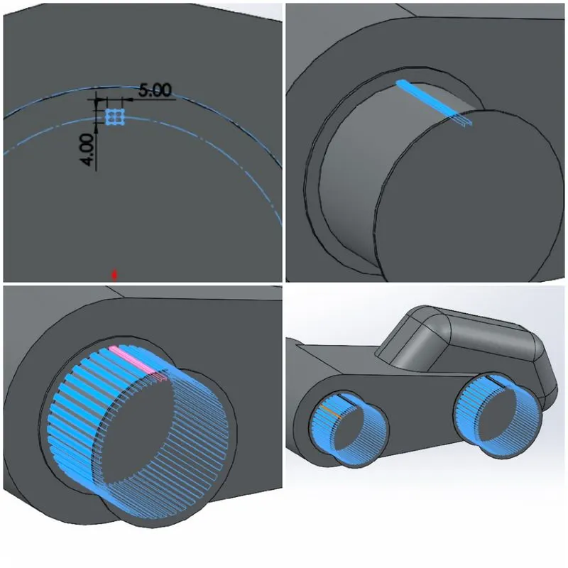
Using the Sketch and Extrude cut feature, the design pattern is cut out from the body as shown in the figure below.
Using the Sketch and Extrude Boss/Base feature, another feature of the engine is created.
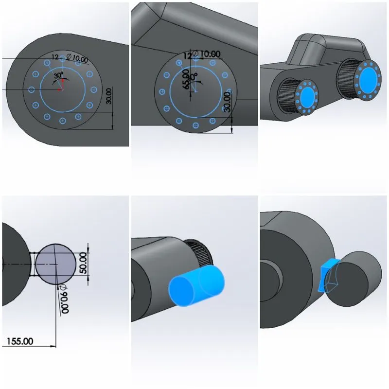
Using the Sketch and Extrude Boss/Base feature, the cylinder of the engine is created.
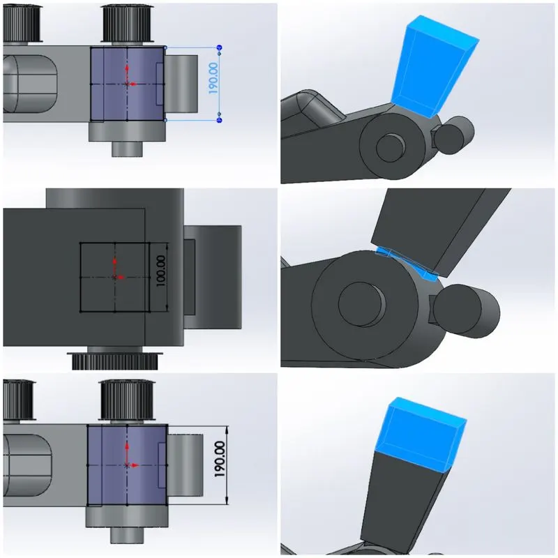
Using the Fillet feature, the sharp edges are rounded. Then using Sketch and Extrude Cut feature, the cooling fin of the engine is created and then the fins are patterned using the Linear pattern feature.
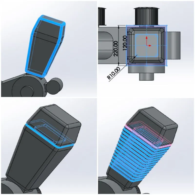
Using the Sketch, Extrude Boss/Base and Fillet feature, the fuel valve is created. Using the Mirror feature, the second cylinder is created.
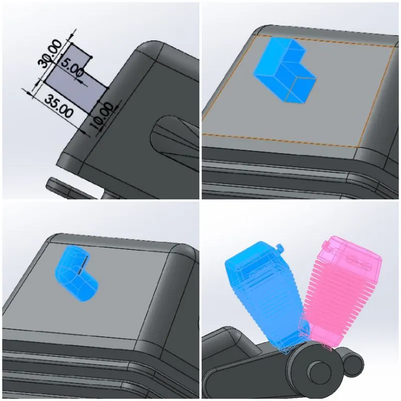
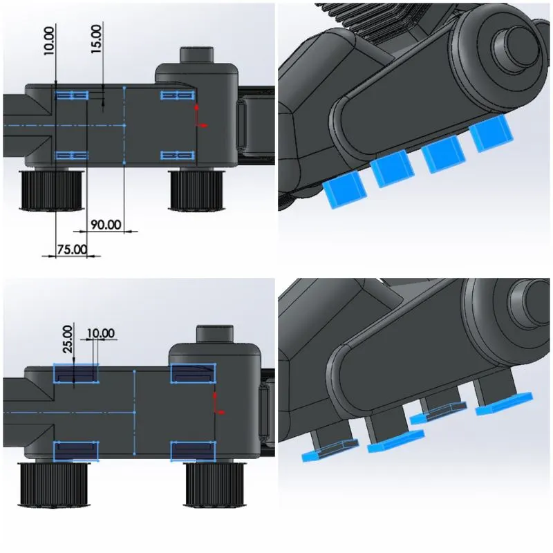
Using the Sketch and Extrude Boss/Base feature, the mounting legs and base of the engine are created.
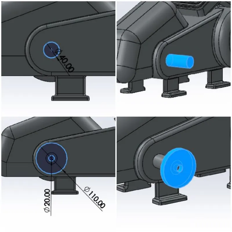
Using the Sketch and Extrude Boss/Base feature, the transmission gear is created.
Using the Sketch and Extrude cut feature, the gear tooth is created and using the Circular pattern the gear teeth are created.
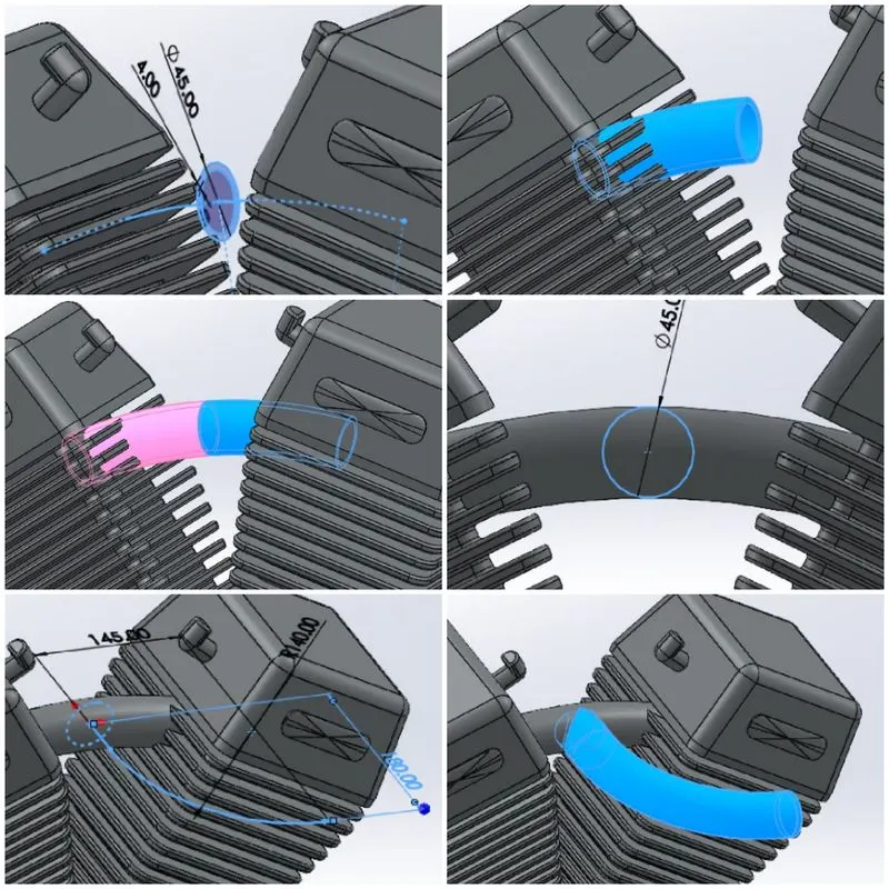
Using the Sketch, Sweep and Mirror feature, the connection tube between the two cylinders are created.
Similarly, using the Sketch and Sweep feature, the initial part of the exhaust pipe is created.
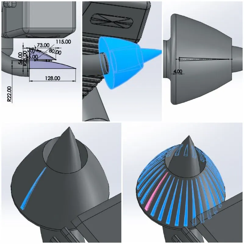
Using the Sketch and Revolve feature, the basic shape of the Air filter is created.
Using the Sketch and Extrude cut feature, the Air inlet gap is created and using the Circular pattern the air inlet gaps are created.
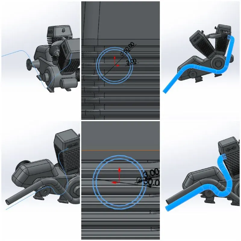
Using the Sketch and Projected curve feature, the 3-D axis of the exhaust pipe is created and using the Sketch and Sweep feature the exhaust pipe is created.
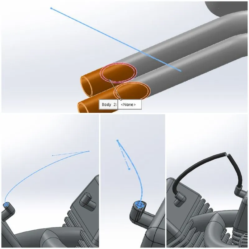
Using the Split feature, the ends of the exhaust pipes are cut at an angle and the residue cut part is deleted using the Consume body option.
Using the Sketch, Projected curve and Sweep feature, the fuel pipes are created.
Using the Combine feature, all the separate parts of the engine are joined into a single body.
Using the Fillet feature, the sharp edges of the engine are rounded.
Finally using the Appearance feature, materials are added to the Engine.
13.Fuel Tank
Features used:
- Sweep-Surface
- Trim-Surface
- Loft-Surface
- Fill-Surface
- Extrude-Surface
- Mirror
- Surface Knit
- Fillet
- Sweep-Cut
- Shell
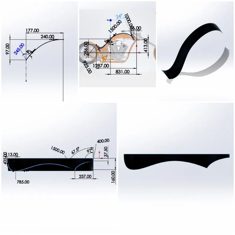
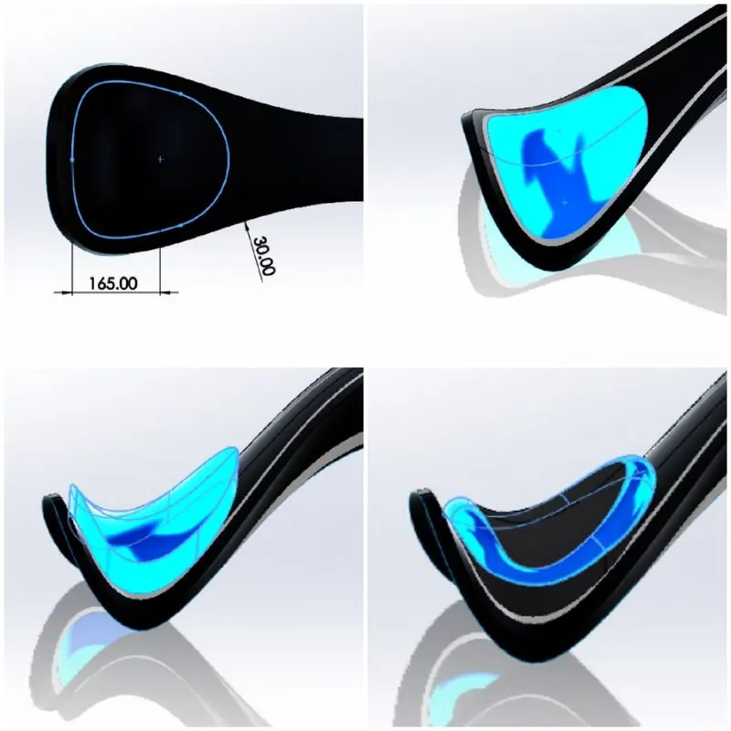
Using the Sketch and Sweep-Surface feature, the upper surface of the fuel tank is created. The Sweep surface feature helps to generate a surface from a surface curve positioned along a path. Here, Sketch 1 is as the sweeping profile and Sketch 2 is used as the Sweeping path.
Using the Sketch and Trim-Surface feature, the 2-D sketch of the top profile of the tank is created and is used to trim the previously created surface in the shape of the 2-D sketch drawn.
Using the Sketch and Projected Curve feature, 3-D curves are created. These 3-D curves are converted to surface using Loft-Surface and Fill-Surface feature. The Loft-surface feature is used to generate a surface from multiple 3-D curves or existing edges with smooth tangency between the selected edges. The Fill-Surface feature helps to generate a surface within any number of sides with a defined boundary.
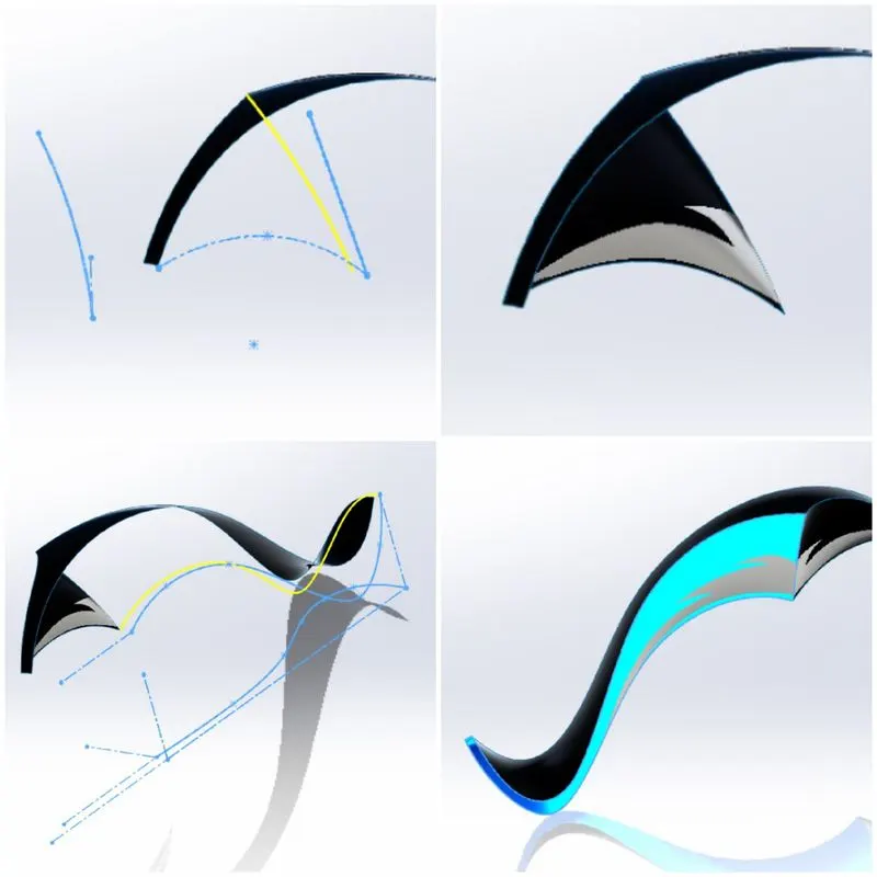
Using the Mirror feature, the above-created surface is mirrored about the mid-plane to provide the fuel tank with complete shape.
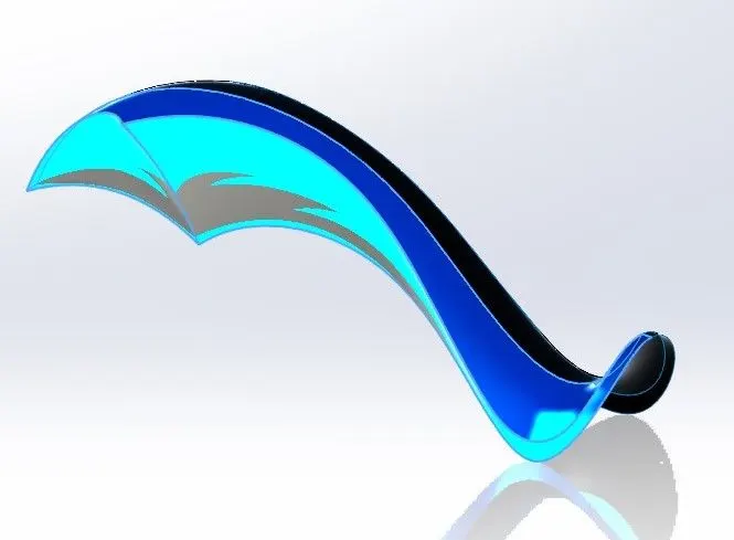
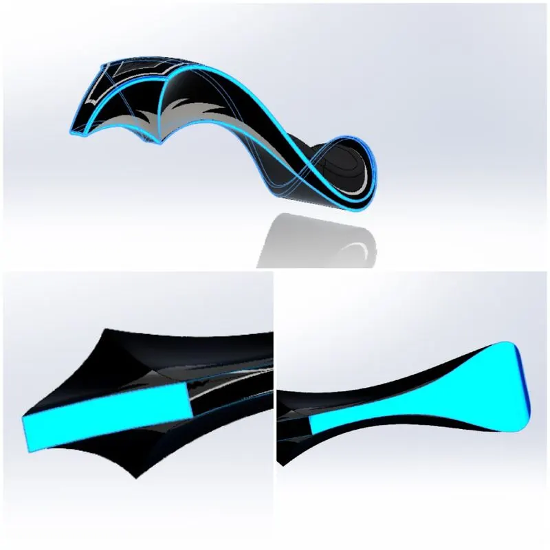
Using the Sketch, Split-Line and Extrude Surface feature, the seat of the American chopper is created.
The Split-line feature helps to project and split a surface in the shape of the 2-D sketch created. The Extrude-Surface feature helps to convert the 2-D surface into 3-D, it also provides the option to specify the height and direction of the extrusion. The sharp edges of the seat are rounded using the Fillet feature.
Using the Fillet feature, the sharp edges of the fuel tank are rounded.
The Bottom part of the fuel tank is enclosed with the surface using Fill-Surface and Loft-Surface feature.
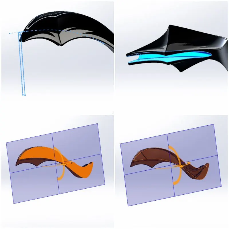
A cavity is made on the fuel tank to accommodate the chassis tube placed below the fuel tank. This cavity is made using the Sketch and Sweep-Cut feature. In the Sweep-cut feature, the 2-D sketch of the cutting profile and the path are created individually using the sketch feature, this cuts the fuel tank in the required shape to accommodate the chassis.
The Surface-Knit feature enables us to join multiple surfaces into a single body.
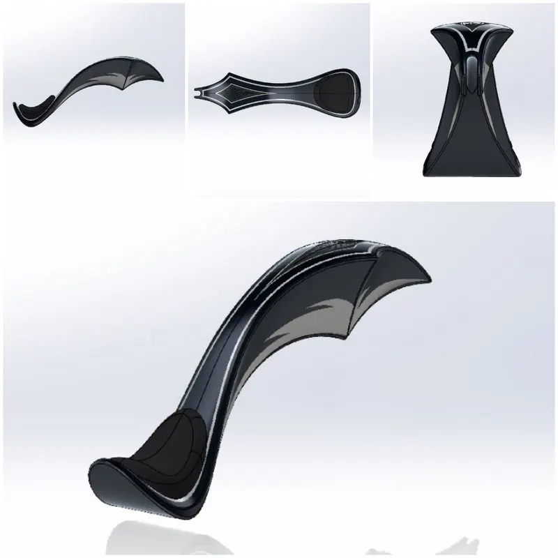
The Shell feature is used to covert the solid body into a hollow body as shown in the figure below.
Finally using the Appearances feature, appropriate material is added to the model.
Assembly of all the Individual Parts into a Single Unit
In the Assembly modelling, each part is inserted and assembled to create the complete model of the American Chopper.
In an assembly, the analogy to sketch relations is Mates. Just as sketch relations define conditions such as tangency, parallelism, and concentricity with respect to sketch geometry, assembly mates define equivalent relations with respect to the individual parts or components, allowing the easy construction of assemblies. Mates define the allowable direction of linear or rotational motion of the components. The component can be moved within its degree of freedom.
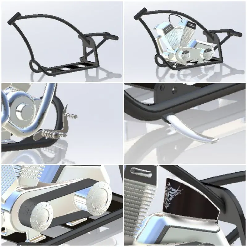
- Initially, the Chassis is inserted into the assembly environment and is fixed at its default location.
- The Engine is then inserted into the assembly. Using the Coincident and the Distance mates, the engine is fixed onto the chassis
- The Pedal is inserted into the assembly. Using the Concentric and the Coincident mates, the pedal is fixed onto the chassis.
- The Kickstand is inserted into the assembly. The Kickstand is fixed onto the chassis using Concentric, Coincident, Limit-angle and Tangent mates.
- The Transmission belt is inserted into the assembly. It is fixed onto position using Concentric, Width and Angle mates.
- The Oil tank is inserted into the assembly. It is fixed onto position using Coincident mate.
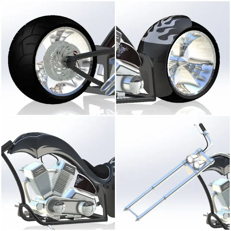
- The Rear wheel is inserted into the assembly and fixed onto its position using Concentric, Coincident and Parallel mates.
- The Rear fender is inserted into the assembly and fixed onto its position using Concentric, Coincident and Parallel mates.
- The Fuel tank is inserted into the assembly and fixed onto its position using Distance and Coincident mates.
- The Front fork is inserted into the assembly and fixed onto its position using Concentric, Width, Limit-angle and Coincident mates.
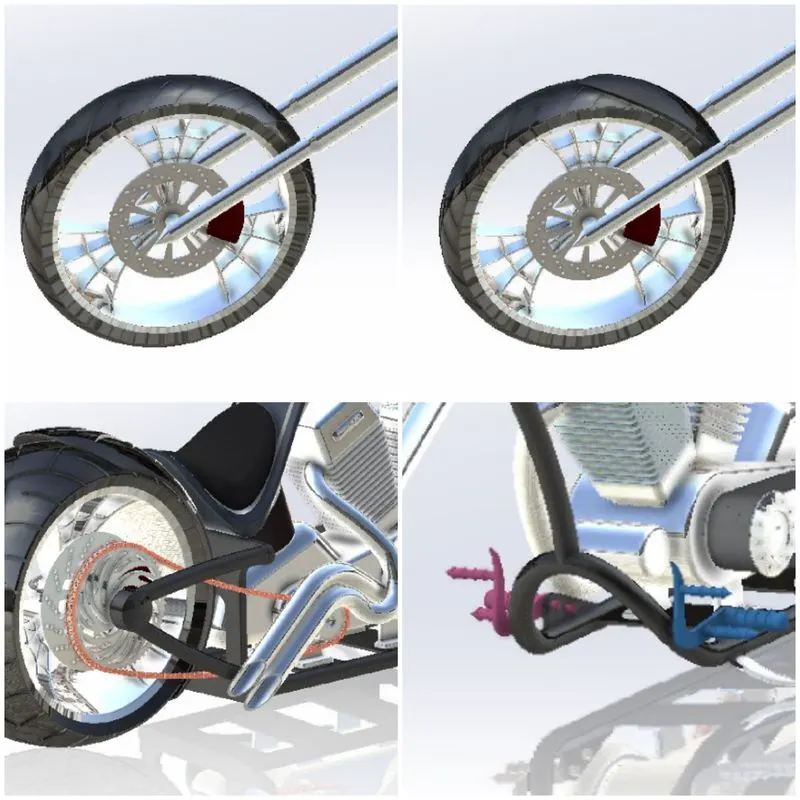
- The Front wheel is inserted into the assembly and fixed onto its position using Concentric, Coincident and Tangent mates.
- The Front fender is inserted into the assembly and fixed onto its position using Coincident mate.
- The Chain is inserted into the assembly and fixed onto its position using Concentric, Width and Parallel mates.
- Using the Mirror component feature, the previously fixed pedal is mirrored to the other side.
The complete assembly of the American Chopper is as shown in the figure below.
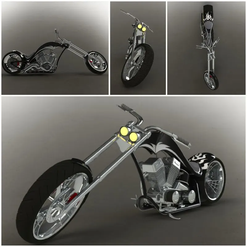
Rendering of the American Chopper model
Rendering or image synthesis is the process of generating a photorealistic or non-photorealistic image from a 2D or 3D model using a computer program. The resulting image is referred to as the render.
SolidWorks has developed an add-in called PhotoView 360, that produces photo-realistic renderings of the models created in SolidWorks. The rendered image incorporates the appearances, lighting, scene, and decals included with the model. SolidWorks Visualize is a standalone application from SolidWorks that enables design teams to produce photorealistic marketing content that communicates a design’s vision, passion, and emotion.
Initially, The model is applied with appropriate materials. Then the Decals are added to the parts.
Once the model is set up with materials and decals, the environment and lighting can be set up. To create a Photo-realistic render, we use High-quality HDRi maps for our environment lighting. HDRi (High Dynamic Range Image) is a panoramic photo, which covers all angles from a single point and contains a large amount of data, which can be used for the illumination of a CG scene.
Multiple cameras can be set up with different views and angles. Once the cameras are set up, the positions of the cameras can be locked and all the camera views can be toggled between each other with a single click. Multiple scenes can be rendered using the queue to render or schedule render options.
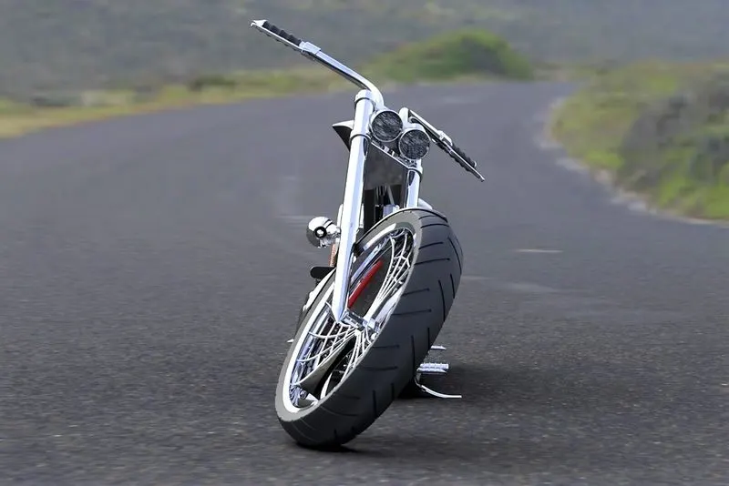
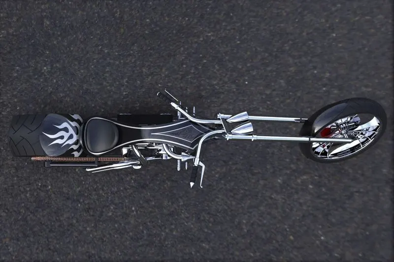
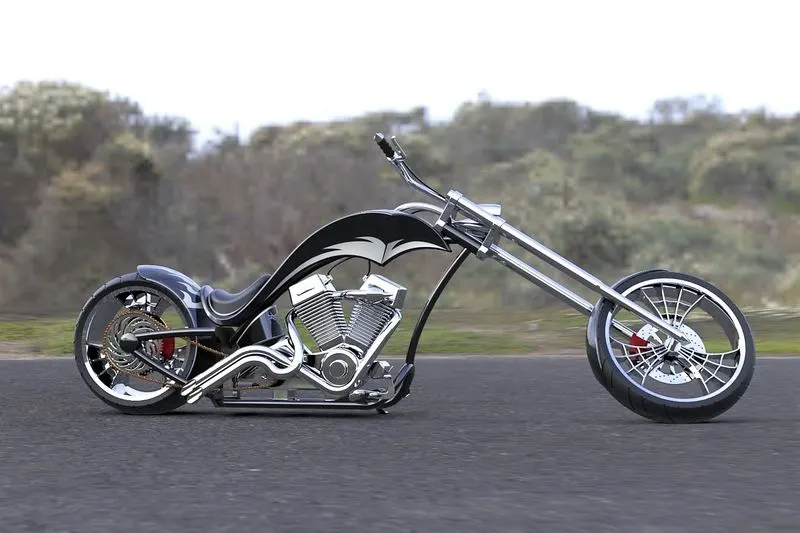
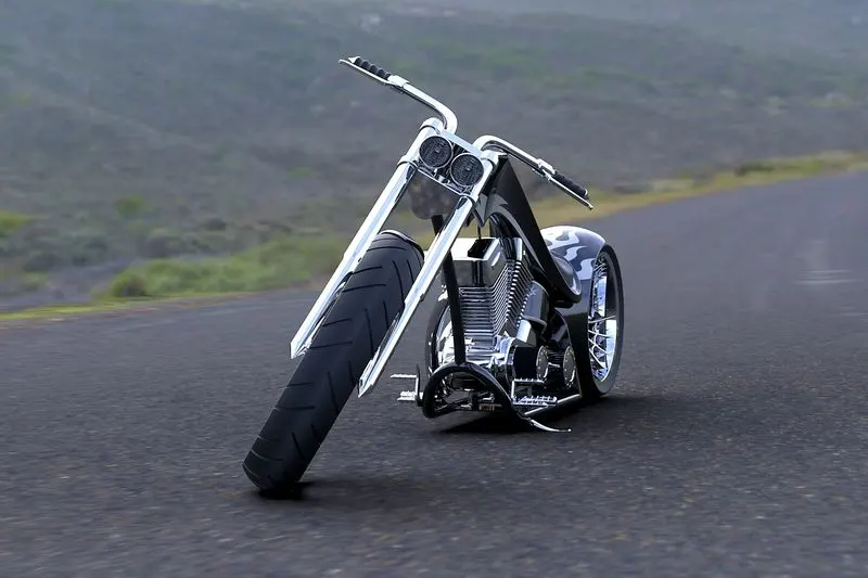
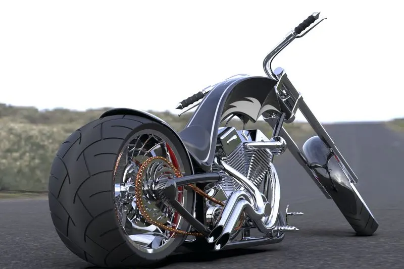
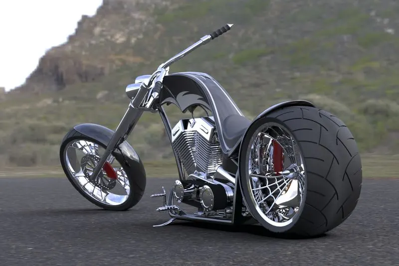
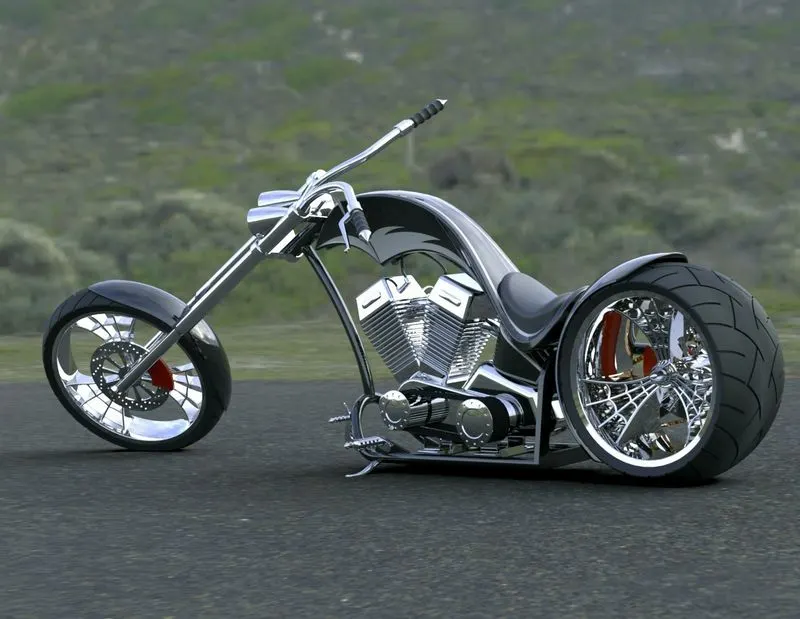
Some of the rendered images of the American Chopper are as shown below :
Conclusion:
The main idea of this project was to learn the Solidworks software, understand its different tools, features and know-how these tools can be utilized in a professional environment.
A better understanding of - The modelling approach on how an existing product is converted into a 3-D model part by part from scratch and then assembling each component to complete the assembly is achieved through this project.
A better understanding of -How high-quality renders of the 3-D model are produced, How materials and textures are applied on the 3-D Models, How multiple cameras, environment and lightings are set up for the renders, How different parameters in the settings and features in the rendering software affects the render-outputs are achieved through this project.