Radar Mast & Final Assembly of Yacht
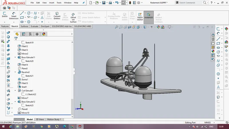
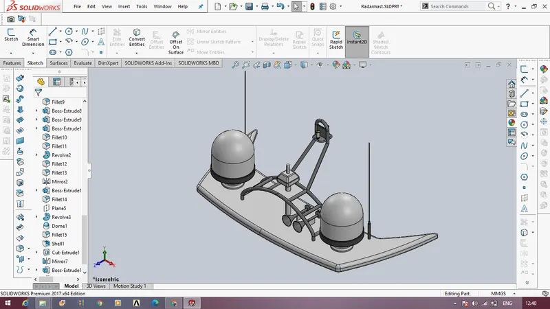
The following snapshots are regarding the feature tree of radarmast.
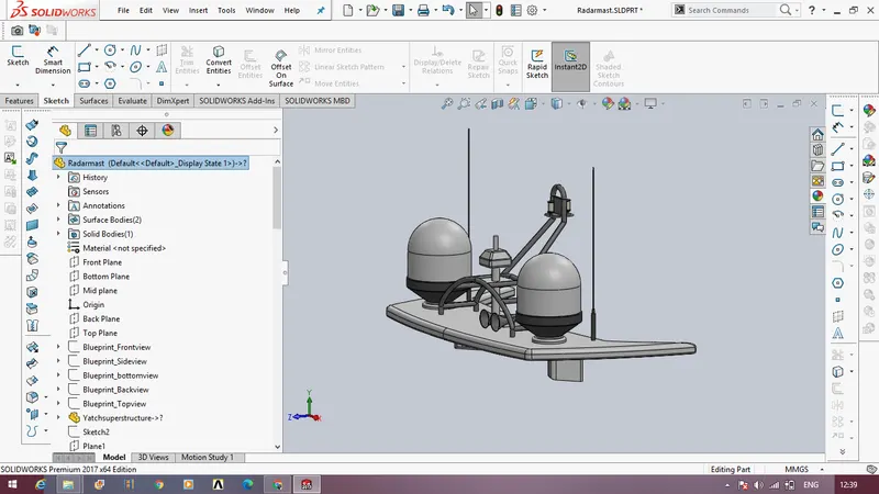
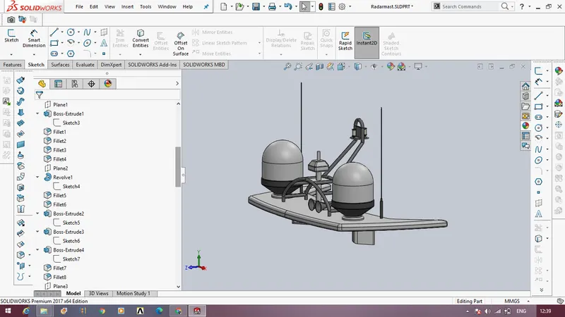
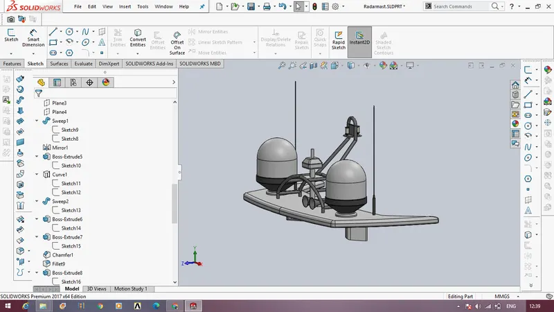
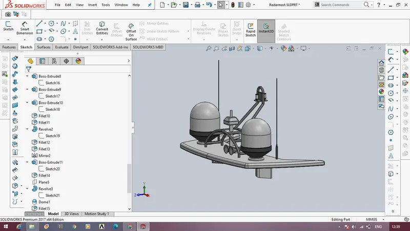
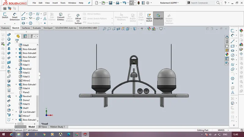
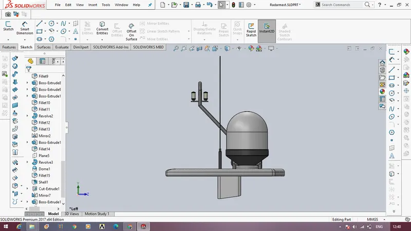
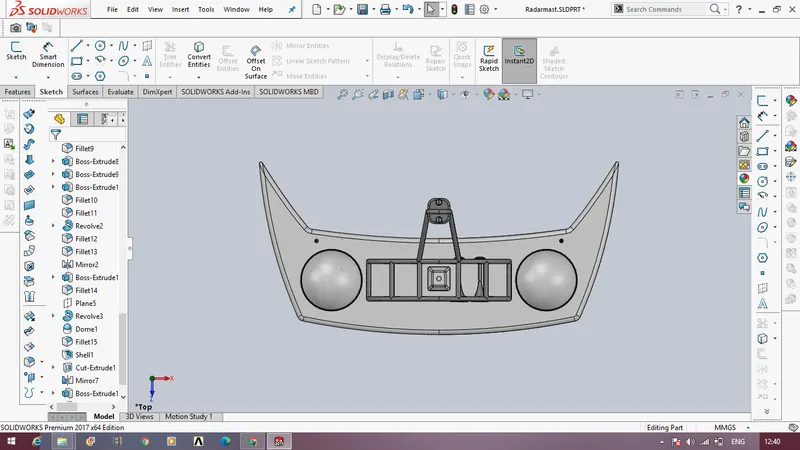
The following snapshots are regarding the different views of the radarmast.
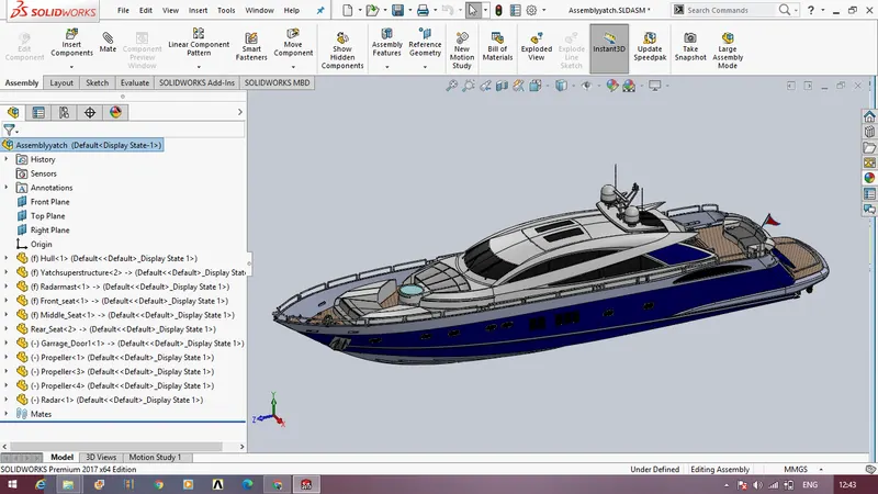
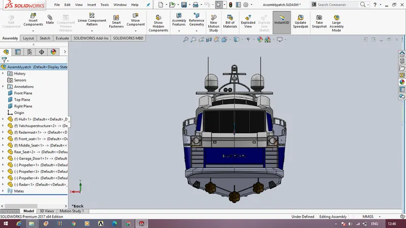
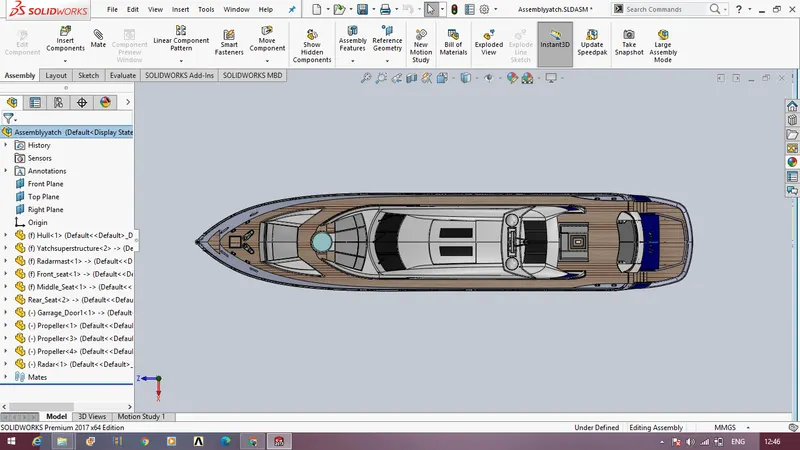
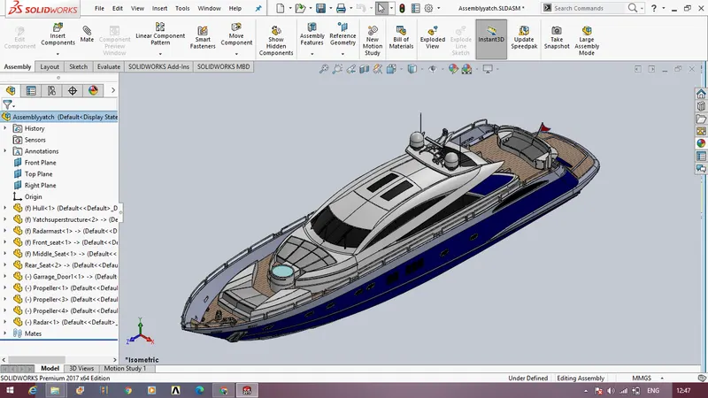
The following are the snapshots of feature tree of assembly of the yacht.
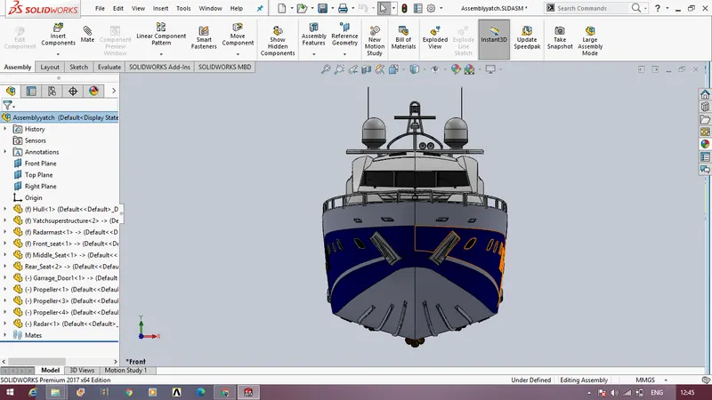
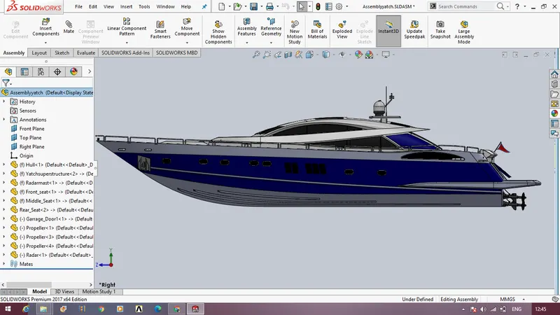
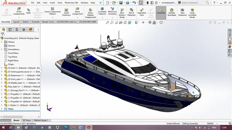
The following snapshots are are different views of the assembly of the yacht.
REPORT WRITING
TITLE : MODELING OF YACHT SUPERMODEL
OBJECTIVE :
The aim of building this yacht super model using solidworks is to get know about several design tools and the parameters that come under designing a solid model using the software. This assembly also teaches how to tackle various problems and how to render the solid model into real time conditions.
INTRODUCTION :
The solidworks software is a solid modeling computer-aided design program which comprises of various tools to build a model . This software is used for planning , visual ideation ,modelling ,prototyping and project management.
Through this project of modeling an yacht super model model various tools have been put into use. It also includes various problem solving techniques and it helps to identify errors and rectify them . The whole of this model includes giving the basic idea of design and also regarding the usage of individual tools and their usages. Through this course it enables to us to know about the various parameters that come before designing a component . Skill Lync program has designed this course in such a way that it is very easy for the beginners to understand and get along with the usage of the software. This report gives a detailed explanation regarding the methodology used in doing this yacht super model.
DESIGN METHODOLOGY :
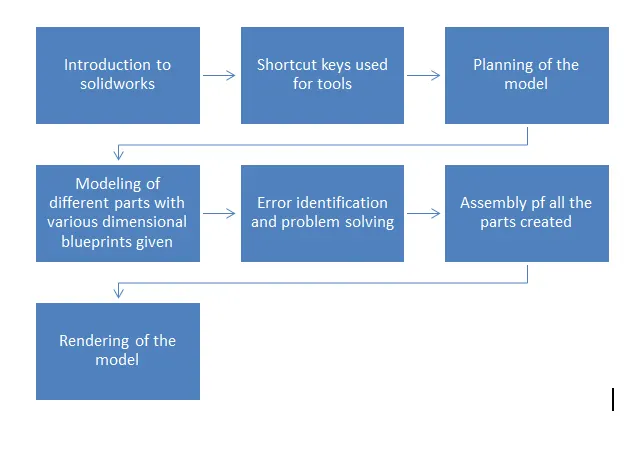
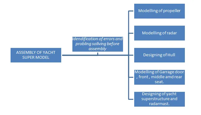
The design approach of the model is explained using the following flowchart.
EXPLANANTION FOR PARTS :
Creating this yacht super model involves designing of various parts which includes using of various surface body and solid model tools.
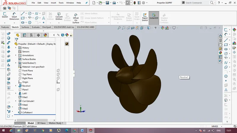
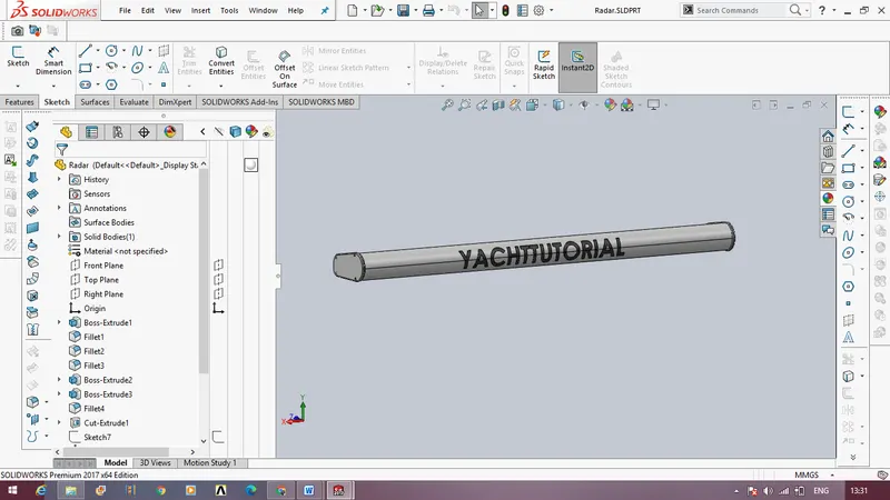
- The designing of yacht supermodel starts off with the designing of the propeller and followed by designing og the radar.
- The designing is done based on the blueprint setup given, the whole model is placed and designed upon the blueprint setup.
- The hull of the yacht is created which covers the bottom part of the supermodel , along with minor details and appearances and the half created hull is then mirrored.
- From the hull part created a garage door is designed. Next keeping the base surface of the hull , the front,middle and rear seats are designed.
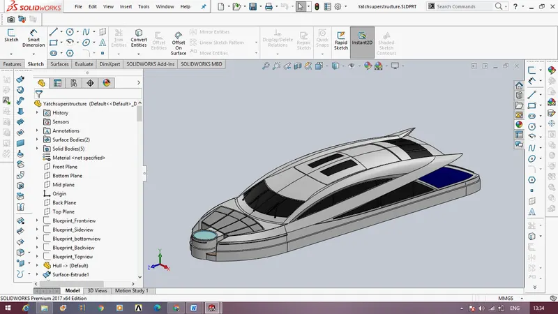
- The next design covers the major part of the model , that is the superstructure of the yacht, it includes usage of various surface tools and thin sheet metal component structures. This superstructure is to be made with lot of precision without any gaps which makes it easy for merging and knitting the surfaces. This superstructure gives out good looks for the yacht with minor details as well.
- The next creation is of radarmast which is the upper part of the yacht which includes light, place for radar and antennas.
- The final step is the Assembly of the yacht. In this step keeping the blueprint as the default alignment the various parts designed of yacht are assembled together along with mates, once the assembly is completed different color speculations are given to the yacht according to various parts, the propellers are also attached accordingly.
- The further step is continued with renders using photoview 360 placing the yacht model in real time conditions and making it look natural by including the shining surfaces and all the reflections to be included along with camera views.
- The next step is to set the background for the yacht and render it using solidworks visualize.
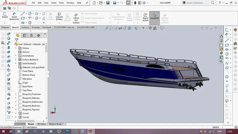
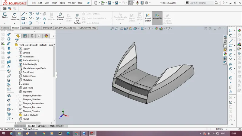
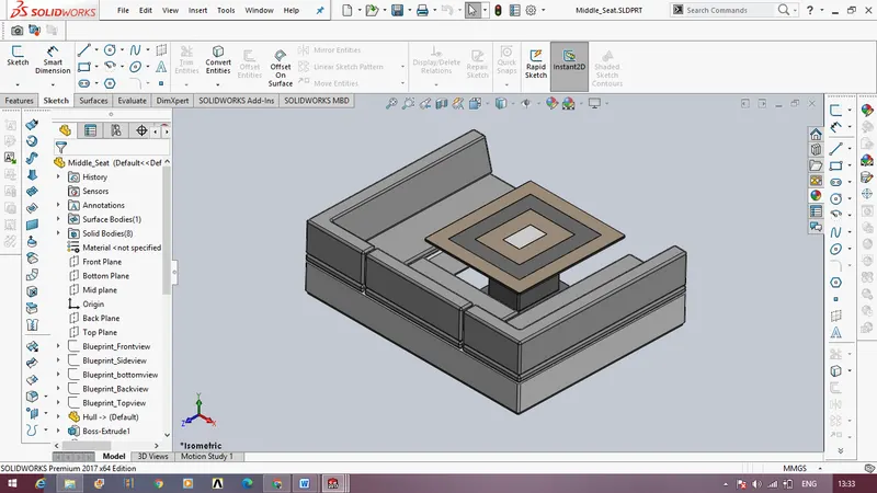
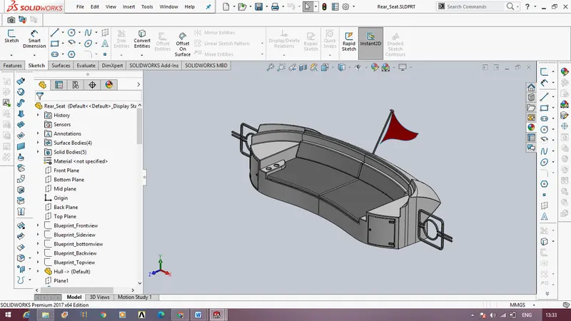
By working to create this model it includes various usage of tools and problem solving methods which helps to learn the solidworks software. The process of designing is neatly organised so that the designing is done step by step and also with better understanding, even the minute details plays important role in designing an object.
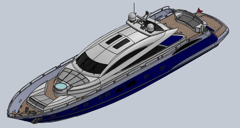
RENDERED IMAGES OF YACHT
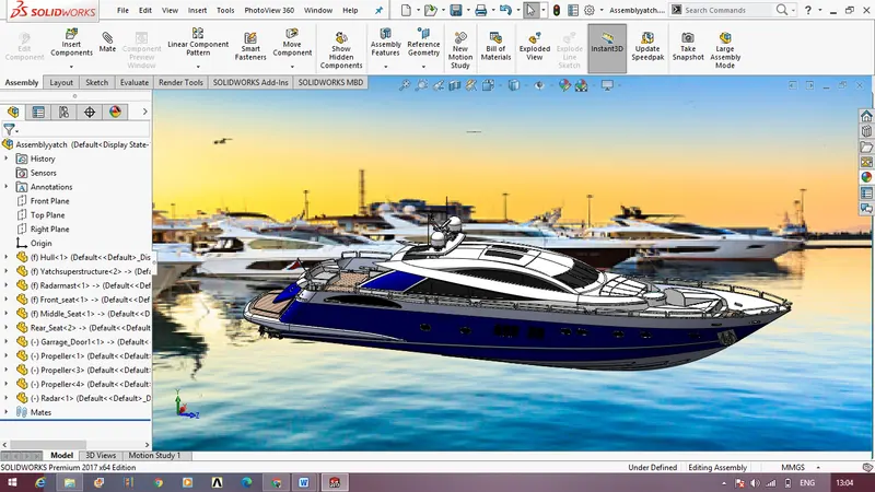
Due to technical issues of the computer, solidworks visualize is not supported, hence the renders are only done through photoview 360 and in photoview 360 also there are some tools that are not supported due to the incapabilities of the system.
CONCLUSION :
The report covered the preview of our learning path and study materials. The use of solidworks has many advantages. It can help to reduce the time it takes to produce the drawing needed in the working environment.
Solidworks software is the most amazing range of mechanical computer aided design tool. It is now considered to be the best according to industry standards that can be obtained for a wide array of designing mechanical engineering services and other industrial purposes. This software is utilized to provide some useful and practical designing software that will allow users to visualize as well as create prototypes of a product in reality and quick time.