Radar Mast & Final Assembly of Yacht
Title: Assembly and Rendering of a Sunseeker Predator Yacht.
Aims and Objectives: The project aims to design a photorealistic yacht. This would be done by accomplishing the following Objectives:
- Design Individual parts of the yacht
- assemble the parts
- Setting the yacht properly for rendering
- Photorealistic rendering of parts and Assembly
Introduction:
The process of developing a system, component, or method to suit desired goals is known as engineering design. It is a decision-making process (often iterative) in which engineering technologies and mathematics are used to transform resources in the most efficient way possible to fulfill a defined goal.
Establishing objectives and criteria, synthesis, analysis, and comparison are all important aspects of the design process.
• Mechanical design refers to the development of mechanical components and systems, such as machines, goods, buildings, gadgets, and instruments.
• Mechanical design, for the most part, relies on mathematics, materials, and engineering-mechanics sciences, as well as engineering drawings and the ability to speak vocally to articulate your ideas clearly.
• Mechanical considerations
This project is about the design of a yacht using solid works from making sketches to solid and surface modeling and making Photorealistic rendering.
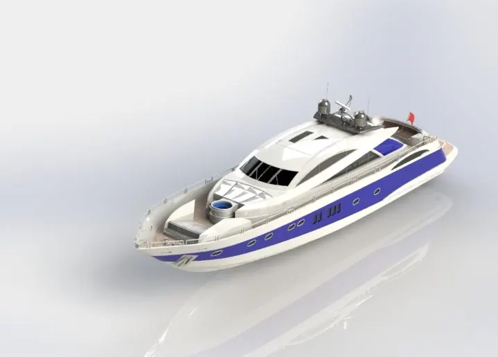
Figure1: Finished Yacht Model
Design Methodology/approach
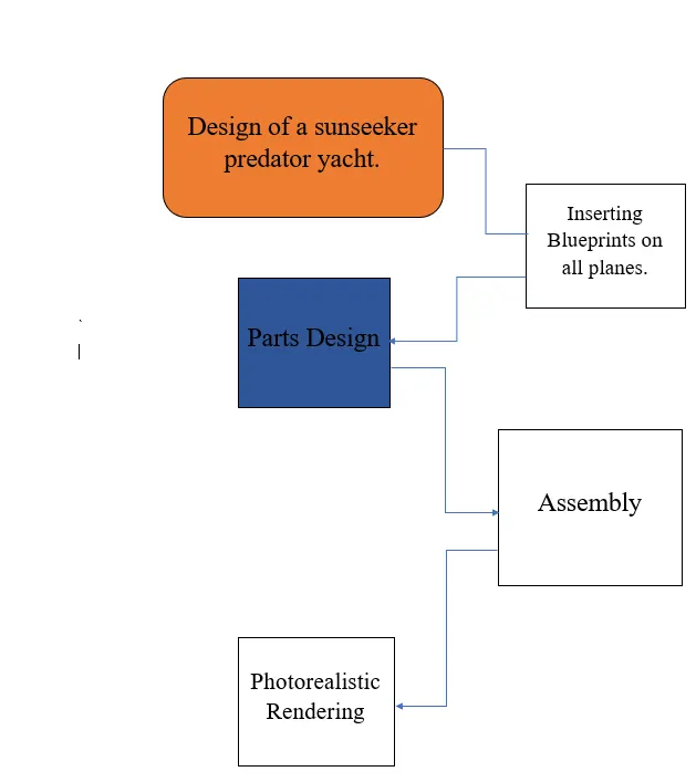
Figure2: Design Methodology Flow chat
The design Methodology will be explained below beginning with the design of individual parts along with an explanation of the features used in the Design. This Project made use of surface modeling which will be described in the design of the Hull and Superstructure respectively.
Setting up the Blueprints
A Blueprint is a technical sketch or a design plan used as the basis of designing a component. Mostly one with complex geometrical shapes. Five blueprints were used in this model representing different views. The front view, Back view, Side view, top view, and Bottom view respectively. The Blueprints were placed on the Top plane, Bottom plane, Front Plane, and Two Other Created Planes like the middle plane and Back Plane.
New Plans can be created in part or assembly documents. These Planes may be used to sketch, produce a section view of a model, and serve as a neutral plane in a draught feature, among other things.
Creating New Planes:
Insert > Reference Geometry > Plane (Reference Geometry toolbar) or Plane (Insert > Reference Geometry > Plane).
Select an object for First Reference or select edge faces in the PropertyManager.
Based on the data, the program generates the most likely plane.
Planes could also be generated by offsetting current existing planes.
Setting up an image/Blueprint on a plane:
- In an open sketch, click Sketch Picture. (Sketch toolbar) or click Tools > Sketch Tools > Sketch Picture.
- In the dialog box, browse to the picture file and click Open. ...
- Set the properties on the first page of the Sketch Picture PropertyManager as necessary. ...
- Click.
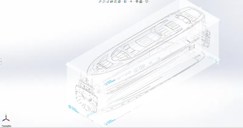
Figure3: Blueprints Setup.
This BluePrint setup is saved as it would be used for modeling some parts of the Yacht.
Parts Design
The Parts of the ship were designed putting into consideration other parts for easy assembly. This is Known as DESIGN FOR ASSEMBLY
Design for assembly (DFA) is a method of creating items that are easy to put together. When a product has fewer parts, it takes less time to build, which lowers assembly costs. Furthermore, if the components are designed with characteristics that make it easier to grab, move, orient, and insert them, assembly time and costs will be reduced. Reducing the number of pieces in an assembly has the additional benefit of lowering the overall cost of the parts in the assembly. This is where the majority of the cost savings from using design for assembly are realized. However, this project does not consider the cost of manufacturing. The Geometries of parts have to fit into each other properly without constraint or loose ends.
The Parts to be Designed includes:
- Propellers
- Radar
- Hull
- Garage Door
- Front Seat
- Middle Seat
- Rear Seat
- SuperStructure and
- Radar Mast
The Modelling of these parts will be explained below. (Note: Features Explained in Modelling a Part will not be repeated if used on other Parts.)
Propellers
A Propeller is a mechanical device that consists of a spinning shaft with two or more wide, angled blades attached to it for moving a boat or aircraft. This model will make use of 3 propellers made of Brass. This is a solid model and Features used Includes;
- Sketch: This is used to make 2D drawings on Planes. That would form the basis of design.
- 3D Sketch
 : The 3D sketch tool, like its 2D version, produces geometry by defining a profile using points, lines, splines, and any other sketchable shape. 3D sketching differs from traditional sketching in that it may exist on numerous planes at the same time, rather than just one.
 - Revolve: By rotating one or more profiles around a centerline, revolves add or remove material. You may make revolved bosses and bases, as well as revolved cuts and surfaces. A solid, a thin feature, or a surface can be used as a revolving feature.
- Loft
 : loft feature allows you to create complicated geometry with just one feature. It accomplishes this by interpolating surfaces between distinct model cross-sections. Sketches, faces, or edges can all be used as cross-sections. These cross-sections are referred to as "Loft Profiles" in the loft interface.
 - Fillet: Fillet/Round gives the portion a rounded internal or exterior face. All edges of a face, choose groups of faces, chosen edges, and edge loops can all be filleted. Fillets could also be added to sketches.
- Circular pattern
 : This is used to Create numerous instances of one or more features using circular patterns that can be spaced equally around an axis. Other Patterns include Linear Pattern, Curve Driven patterns, Sketch Driven patterns, Table driven patterns, Fill Patterns, and Variable Patterns.
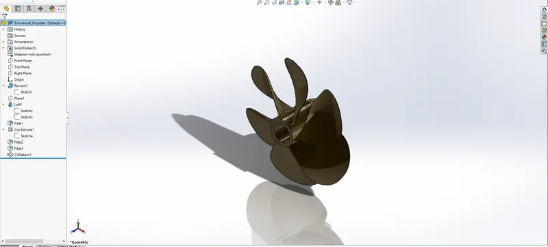
Figure 4: Propeller Design
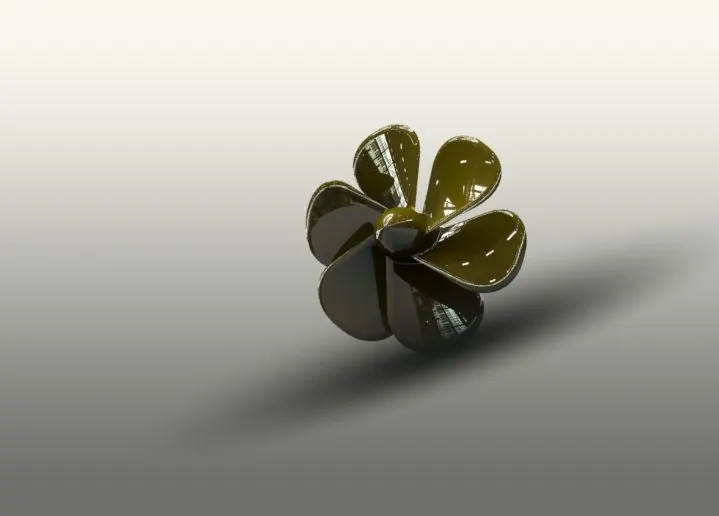
Figure 5: Rendered Propeller Design
The Radar
This is a System that uses radio waves to detect the existence, direction, distance, and speed of airplanes, ships, and other objects by sending out pulses of radio waves that are reflected in the source. This could also be used for Communication and Finding Direction. The Features used to model this Includes:
- Boss-Extrude
 : The Boss-Extrude/Base functionality creates a 3D model with the sketch or face you choose.
 - Cut-Extrude
 : The material is removed from the component using the extruded cut function. Extruded Boss/End Base's Condition, Draft, and Thin Feature choices are the same.
 - Mirror
 : Creates a mirrored replica of a feature (or numerous features) on a face or plane. You can choose either the feature or the faces that make up the feature. Mirrored Bodies To make a mirror entity, select a body from a single model or a multibody portion.
 - Split-Line
 : Split Line. is a tool that projects an entity (sketch, solid, surface, face, plane, or surface spline) onto surfaces, curved or planar faces. It splits a single face into several different ones. With a single command, you may separate curves on several bodies.
 - Sketch texts
 : Writings on 2D planes could be made on solid works and Imprinted on a surface as demonstrated on the Radar. Sketch lines May be needed to make Texts.
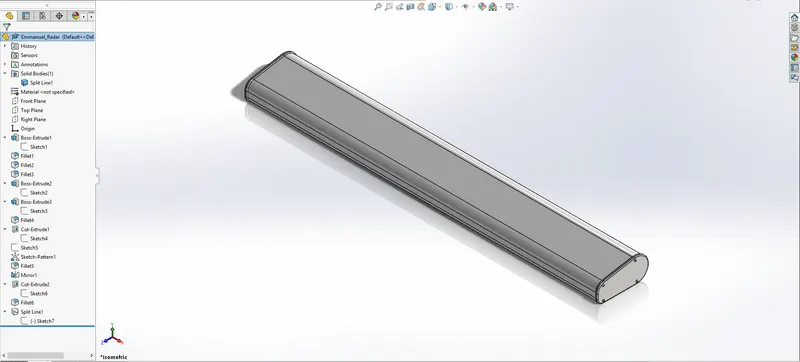
Figure 6: The Radar
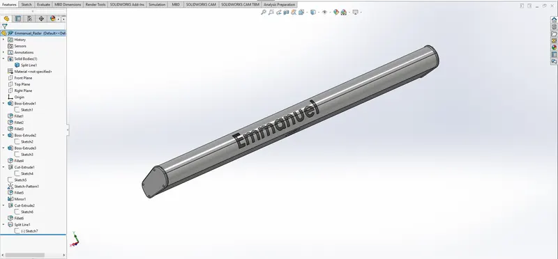
Figure 7: Text on Radar.
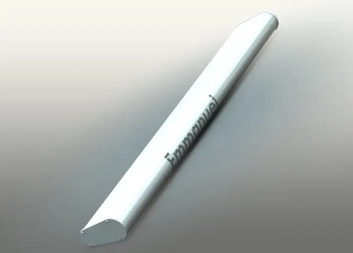
Figure 8: Rendered Radar
The Hull
This is the bottom, sides, and deck of a ship or other vessel, excluding the masts, superstructure, rigging, engines, and other equipment. Surface modeling is Being Introduced in the modeling. The blueprint setup was opened and the model was designed concerning the blueprint which was later renamed. The Features used for the model includes:
- Projected Curve: This is Used to make a 3D curve, project a drawn curve onto a model face. You may also use drawings on two intersecting planes to build a 3D curve that represents the intersection of two extruded surfaces.
From a single drawing, you may make several closed or open-contour projected curves. 3D drawings can also be used as input for the Projected Curve tool.
- Dome
 : This creates a semi_circular design on a surface/ Plane. The Intensity can be adjusted accordingly.
 - Sweep
 : A sweep is a tool that moves a profile along a route to generate a solid, a cut, or a surface feature. To make a solid, drag a profile down a path with the Swept Boss tool. One or more closed contours can be seen in the profile.
 - Helix/Spiral: The Helix and Spiral tools may be used to create 3D curves that can subsequently be utilized as sweep paths. Perfect for making springs or threads in Screws.
- Linear Pattern: This Creates numerous instances of one or more features using linear patterns that can be spaced equally along one or two linear routes.
- Surface Loft: Just like the Loft Boss/Base, This creates complex surface geometry using the cross-section of Sketches. Forming Surfaces rather than Solids.
- Surface Trim: This is used to cut out unwanted surfaces. Two surfaces should Intersect for this to work. You can use a surface, plane, or sketch as a trim tool to trim intersecting surfaces. You can also use a surface in conjunction with additional surfaces, as mutual trim tools.
- Surface Extrude: Like The Boss Extrude, You can create extruded surfaces from models that include 2D or 3D faces and knit the extruded surfaces to surrounding features. Thickness could be assigned to these Extruded surfaces.
- Surface Knit: This Combines Two or more surfaces into one. Solid Bodies could be formed if there are no Gaps between the Knitted surfaces.
- Surface Fill: Within a boundary defined by existing model edges, drawings, or curves, including composite curves, the Filled Surface feature creates a surface patch with any number of sides. This feature may be used to create a surface to fill a gap in a model.
- Shell
 : The shell tool hollows into a section, leaving the faces you choose open, and creating thin-walled features on the rest.
You can shell a solid part to create a closed, hollow model if you don't pick any faces on the model. You may also use several thicknesses to shell a model.
- Delete Face: This is used to Delete Faces from Bodies. In this Project, Faces were Deleted and recreated to correct Holes/ Patches in the Structure.
- Body-Delete/Keep: Using the Remove/Keep Body functionality, you may choose which bodies to keep or delete. Working with multibody components with numerous configurations is a good example of this. A Body was Deleted and Kept out of the Hull to Design the Garage Door in this design.
- Surface-Offset: This would offset or create a replica of the selected surface. the distance between the new surface and the reference surface is termed an offset.
- Chamfer
 : The chamfer tool adds a beveled edge, face, or vertex to a specified edge, face, or vertex. In the Chamfer Property Manager or the graphics area, set the Distance and Angle. A manipulator arrow appears, pointing in the direction of the distance measurement.
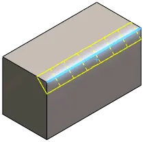
16. Ruled Surface: This is used to create a surface that could be tangent or normal to a Given edge. The angle could also be given and distance.
17. Surface Extend: By selecting an edge, many edges, or a face, you may extend a surface.
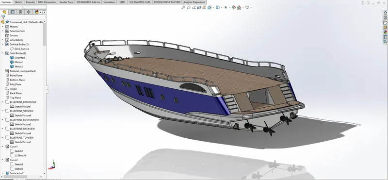
Figure 9: Hull Design.
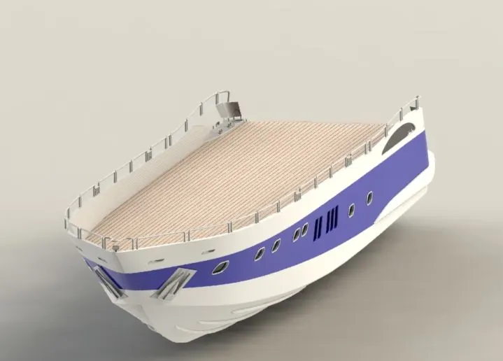
Figure 10: Rendered Hull Design.
The Garage Door
This part was created from the deleted Body Extracted and Saved from the Hull Design. The Features used in Modifying this body to form the hull have been Explained Above. These Features Include:
- Cut-Extrude
- Shell
- Fillet
- Mirror.
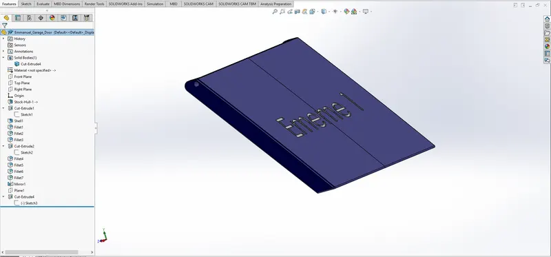
Figure 11: Garage Door
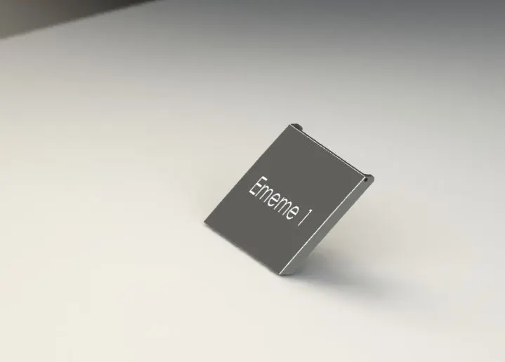
Figure 12: Rendered Garage Door
Front Seat
This is a seat in front of the yacht. This was designed regarding the surface of the hull which was Imported. This method made assembly easy. The BluePrint setup was also used for proper Sketches and Easy assembly Later. All Surface Features used Have been Explained Above.
Other Part Could be imported into an Existing part in solid works by:
- With a part document open, click Insert Part (Features toolbar) or Insert > Part.
- Browse to a part document and click Open.
The Insert Part PropertyManager appears.
- Under Transfer, select any combination of items from the inserted part to be included in the derived part. You can include items such as custom properties, cut-list properties, sketches, and model dimensions.
All transferred elements of the inserted part are placed in folders under the inserted part in the FeatureManager design tree.
- Under Locate Part, select Locate part with Move/Copy feature to define a location for the inserted part in the Locate Part PropertyManager.
- Optionally, if you want to independently edit the features of the inserted part without affecting the original part, under Link, click Break link to the original part.
You can also break the link to the original part later by listing the derived part's external references and selecting Break All. Once you break the link to the original, you cannot restore it.
- Click
(These Steps were Gotten from: https://help.solidworks.com/2017/English/SolidWorks/sldworks/t_Inserting_a_Part_into_Another_Part.htm ).
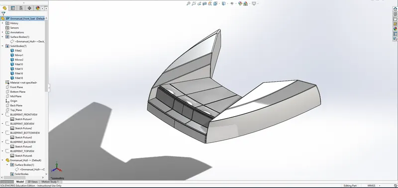
Figure 13: Front Seat
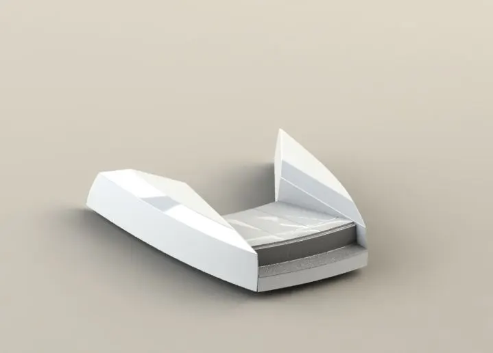
Figure 14:Rendered Front Seat
Middle Seat
Just like The Front Seat, The Blueprint setup was used to model this part and the deck surface was imported as well.
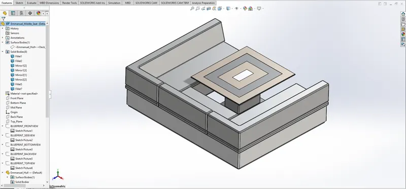
Figure 15: Middle Seat
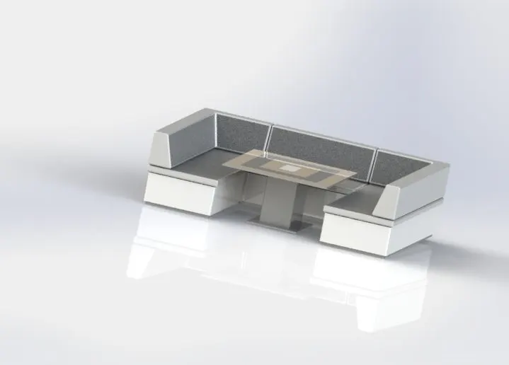
Figure 16: Rendered Middle Seat
REAR SEAT
The same Process and features used in the Front and rear seat were Applied. These Seats have different geometries as provided by BluePrint.
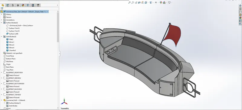
Figure 17: Rear Seat
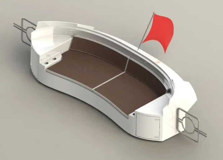
Figure 18: Rendered Rear Seat
The Super Structure.
This could be referred to as the Head of the Ship. Design Features and patterns used are similar to that of the hull. The Blueprints were also used as a reference for the design.
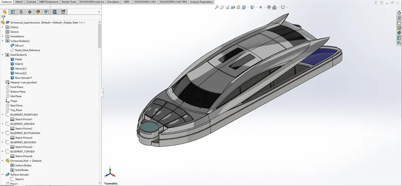
Figure 19: Super Structure
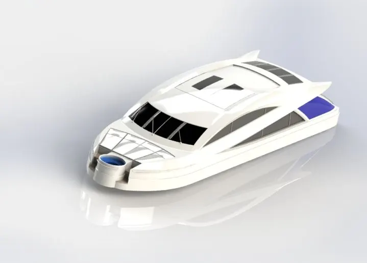
Figure 20: Rendered Super Structure
The Radar Mast
This Part was designed on a surface created on the superstructure. The blueprint was also used for the proper design of parts. Features used have been explained Above.
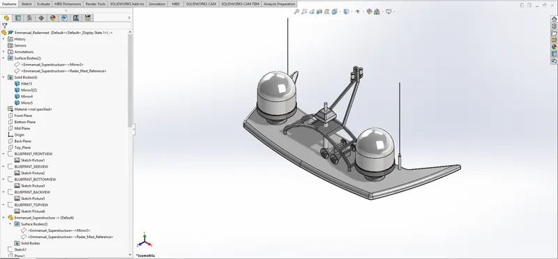
Figure 21: Radar Mast.
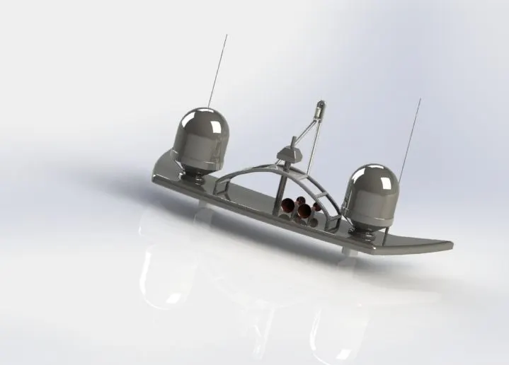
Figure 22: Rendered Radar Mast.
The Assembly
After all, Parts have been created, An assembly can be made to form the Sunseeker Predator Yacht.
The MATES feature in the assembly is used to attach these parts with respect to their geometries. The steps taken to carry out the assembly includes the following:
- Insert the Parts by clicking on Insert Components
- Browse to the desired Part to insert
- Click on the Check Box to Drop the part on the Assigned Plane Or Click anywhere on the screen to drop parts on specific locations.
Apart from the Radar, Garage Door, and Propellers, All Other Parts were created regarding the Blueprint, Hull Surface, and Superstructure top surface. Hence, These Parts don't need to be placed anywhere on the screen. They will be fixed to their desired location when the check is Ticked. The radar, Garage door, and propellers would be mated Manually using the Mates Feature in the Assembly.
Two Main Kinds of Mates were used to attach these bodies.
- The coincident Mate: A coincident mate is a mate between two features that you desire to coincide with one other, as the name implies. It's most commonly used to make two Bodies / Planes / Surfaces parallel and coincident. A distance could also be applied to the coincident mate to define the distance apart from each other 0mm meaning both surfaces are touching.
- Concentric Mate: Two cylindrical faces are forced to become concentric by a concentric mate.
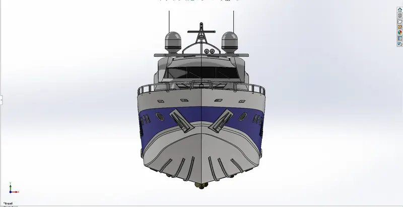
Figure 23: Front View of Yacht Assembly
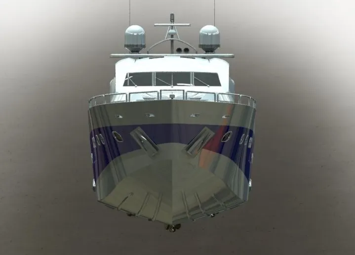
Figure 24: Rendered Front View of a Yacht Assembly
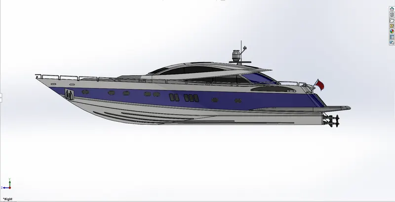
Figure 25: Side view of a Yacht Assembly
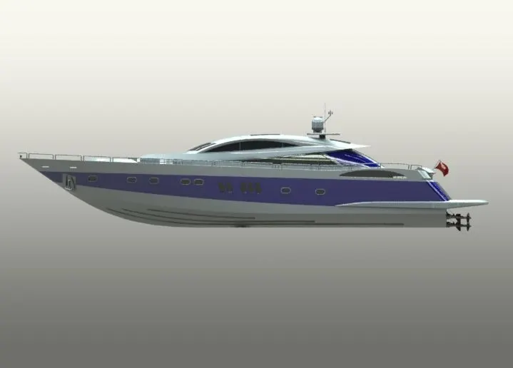
Figure 26: Rendered Side view of a Yacht Assembly
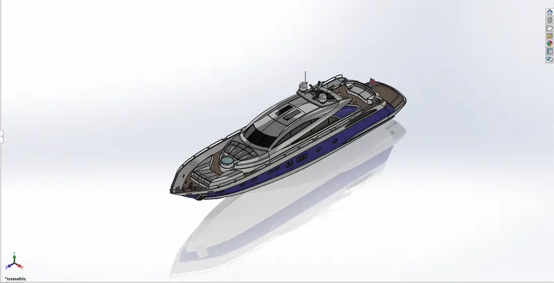
Figure 27: Isometric View of a Yacht Assembly
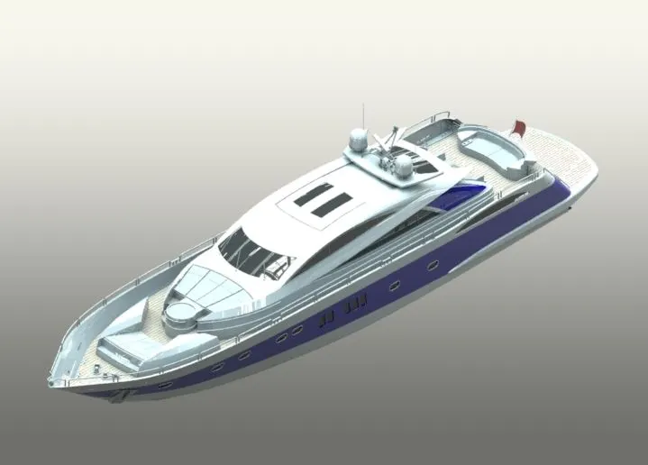
Figure 28: Rendered Isometric view of a yacht assembly
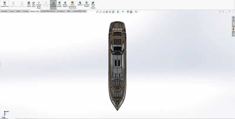
Figure 29: Top View of a yacht Assembly
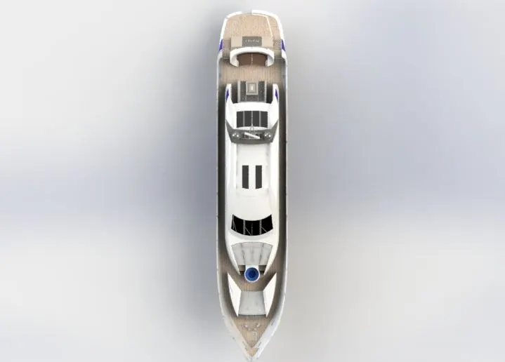
Figure 30: Rendered Top view of a yacht Assembly
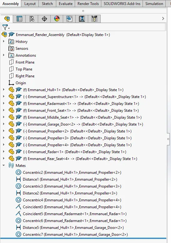
Figure 31: The Feature Tree of an Assembly
Photorealistic Rendering.
Photorealistic rendering is a sort of 3D rendering in which the final product is difficult to tell apart from reality or a photograph. An Inbuilt tool needs to be enabled in solid works called Photoview 360 for the program to run. PhotoView 360 is a SOLIDWORKS add-in that renders SOLIDWORKS models in photo-realistic renderings. The produced image includes all of the model's appearances, lighting, scene, and decals.
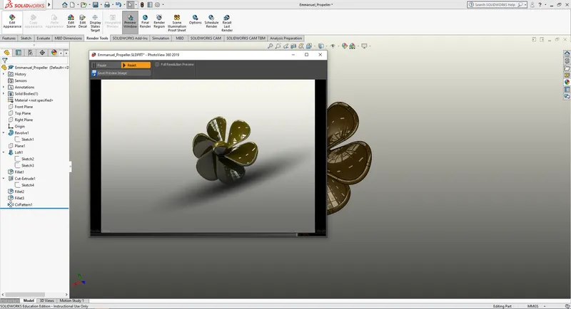
Figure 32: Showing a preview of the rendered image.
Before Rendering, Other Protocols need to be observed Like setting up the Appearance and assigning materials, colors, and background images to the objects.
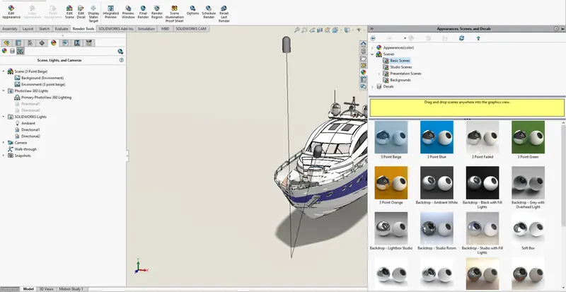
Figure 33: Assigning Appearance
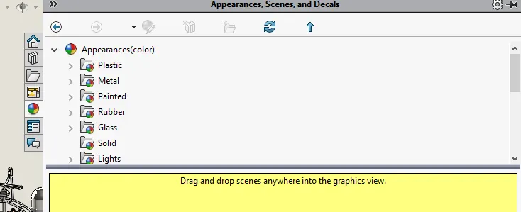
Figure 34: Showing materials option for editing.
Adding the necessary Decals is also an important step in Rendering. A decal or transfer is a printed pattern or picture on a plastic, cloth, paper, or ceramic substrate that may be transferred to another surface with the use of heat or water. In our design, the patterns imprinted on the floor Hull Surface and Superstructure Steps are called decals.
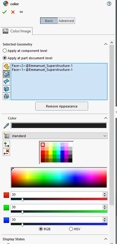
Figure 35: Editing the Color of Parts
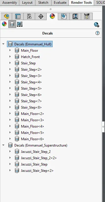
Figure 36: Decal Images and Positions on the Yacht.
Rendering and Perspective
Add a camera with perspective or at the very least switch on perspective view when creating a PhotoView 360 rendering for the most realistic results.
After you create the camera sled, you can add the camera, attach it to the camera sled, and compose the camera view.
To add and position the camera,
- Open the assembly document that includes the camera sled.
- Click Front (Standard toolbar).
- Right-click Lights, Cameras, and Scene (MotionManager tree) and select Add Camera.
The screen splits into viewports, and the Camera PropertyManager appears.
- In the PropertyManager, under Target Point, select Target by selection.
- In the graphics area, select a sketch entity and use it to attach the Target Point to the camera sled.
You can center the Field of View by selecting the midpoint of the line entity.
- In the PropertyManager, under Camera Position, click Position by selection.
- In the graphics area, select a sketch entity and use it to specify the Camera Position.
- Drag the Field of View to compose the shot by using the viewport for reference.
Drag the Field of View rectangle up and down, normal to the camera axis, to adjust the angle of view of the model. Check your results on the right pane of the viewport. - In the PropertyManager, under Camera Rotation, click Set roll by selection.
- In the graphics area, select a face to prevent camera roll when you drag the camera sled to create the path.
- Click.
By using these settings and moving the camera sled horizontally, you can create a camera sled animation in which the camera moves toward the model. Subject to your Field of View settings, you can maintain the model in the frame throughout the animation. (These Steps were Gotten from: https://help.solidworks.com/2018/English/SolidWorks/motionstudies/t_adding_camera_positioning_sled.htm?id=3cb8483bb42f4694b50098b5e3164ce1).
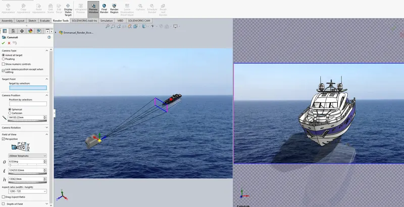
Figure 37: Setting up a Camera
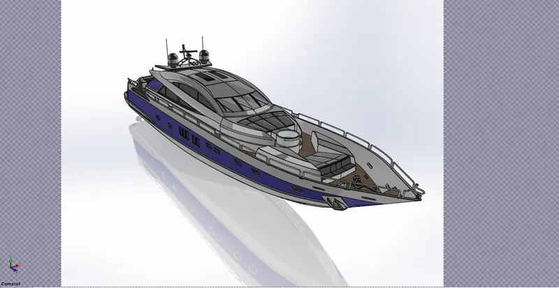
Figure 37: Camera 1
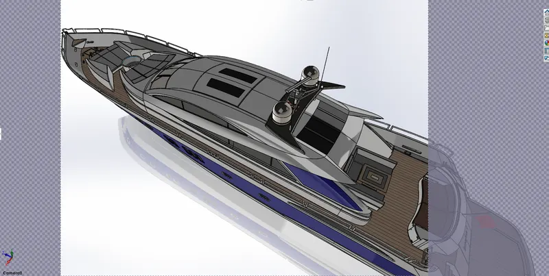
Figure 38: Camera 2
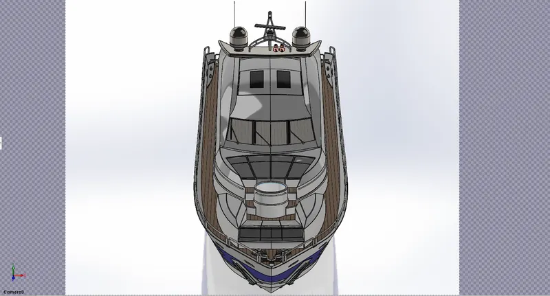
Figure 39: Camera 3
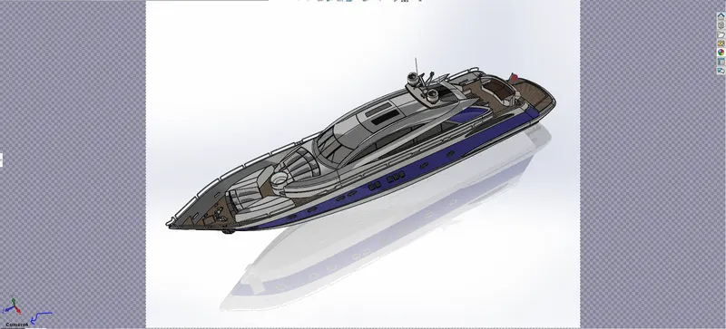
Figure 40: Camera 4
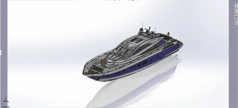
Figure 41: Camera 5
Lighting
Setting up the Lighting is also important before rendering. Here a spotlight is added to give the impression of lights been emitted from the lamps. The material of the Lamps could be adjusted to reflect light on a dark background. Other Lighting Options are also available in Photo view 360.
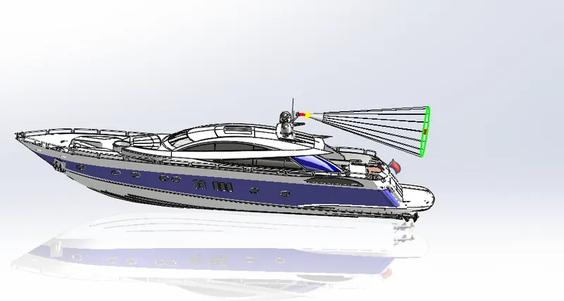
Figure 42: Adding Spot Lights
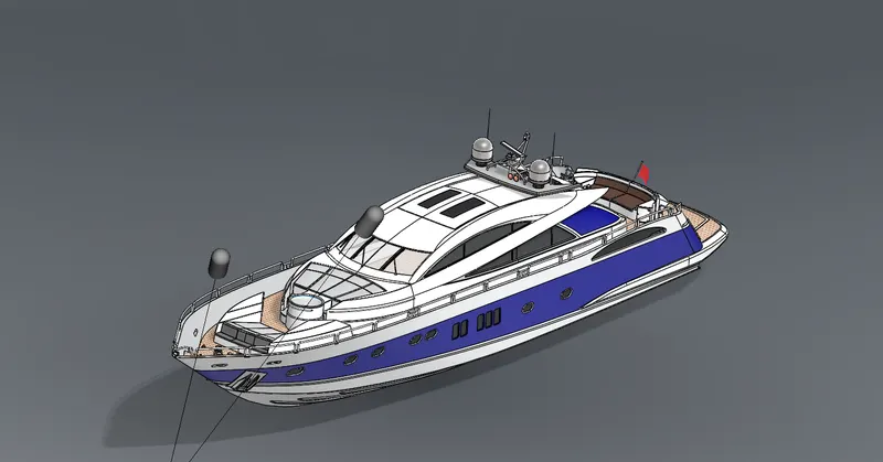
Figure 43: Showing Directional Lights from Background
Setting Background Images
The scene could be edited to make the view more realistic. Adding the appropriate background image can help accomplish that.
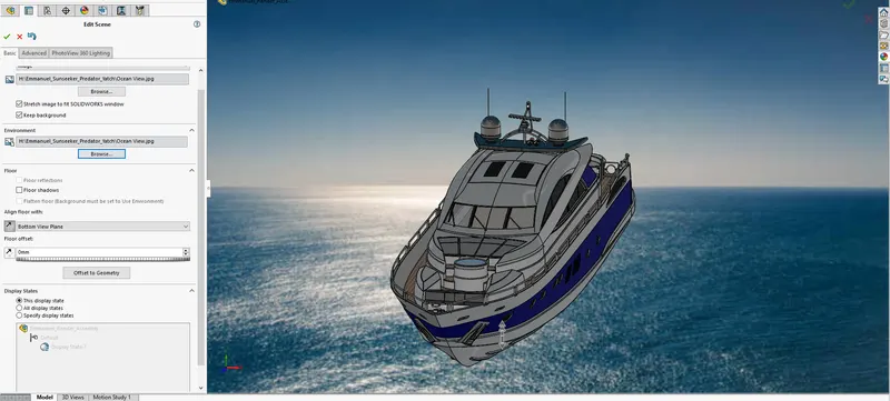
Figure 44: Adding a Background Image
After this is Done, A review of the rendering could be done to help make adjustments
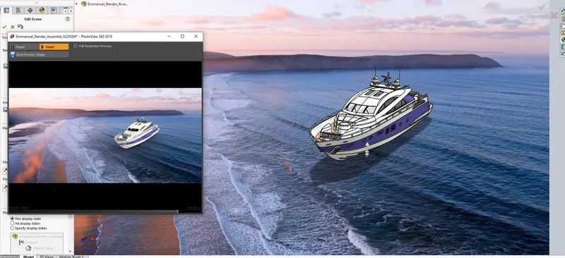
Figure 45: Opening the review Window
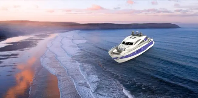
Figure 46: Reviewed Rendered Image
When you are Fine with the outcome of the render, you can go ahead to make a more detailed final render of the Part/assembly.
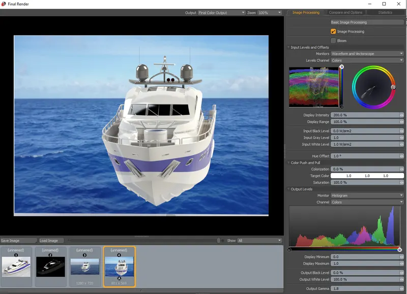
Figure 47: Final Rendering Window.
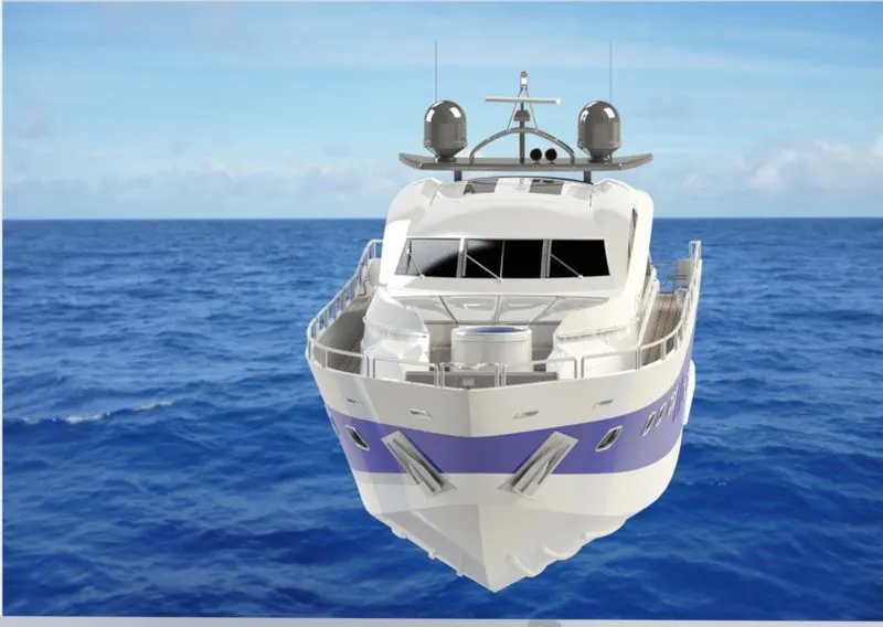
Figure 48: Final Render Image
Other Standalone Softwares could be used to perform rendering operations which include Solid works visualize.
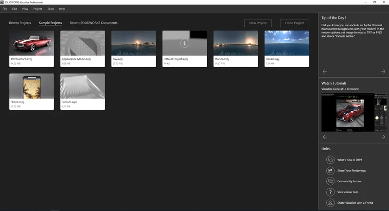
Figure 49: Solid works Visualize
Before making a render, The Software allows you to Edit the appearance by adding decals, materials, and color as well as background scenes.
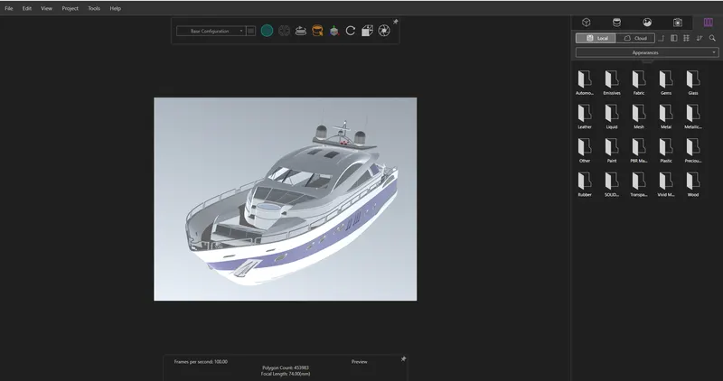
Figure 40: Editing the Appearance in Solid works visualize
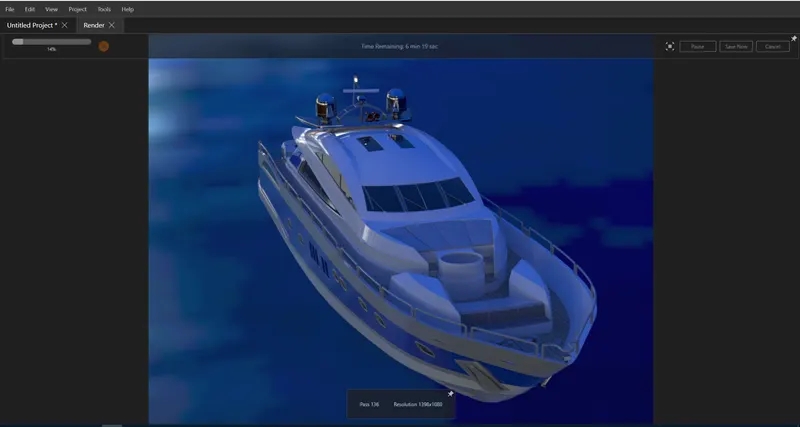
Figure 41: Rendering Process
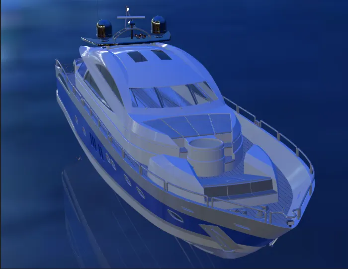
Figure 42: Final Rendered Image
Conclusion
This Project has given an extensive Demonstration of the use of solid works to model complex geometries Using surfacing and demonstrating how parts could be Assembled and giving a photo-realistic image.
The following are reasons why solid works is a recommended Design Software:
1. 3D design that is efficient
SOLIDWORKS is a parametric design modular that allows you to alter the design at any point throughout the design process. PhotoView 360 can generate advanced photo-realistic renderings and animations, while RealView graphics enable you to see your design in real-time. Both tools will provide you a good idea of how your design will appear before it is completed, and they may be a valuable asset when showing your work to clients. You may examine each section of the design, see correct mass characteristics, and check for interference without having to construct or produce the product, saving time and money and minimising the number of prototypes required. All of this will enhance productivity by speeding up the design process as we know it.
2. Compatibility between the customer and the supplier
It is critical to use a well-known CAD system. Because of SOLIDWORKS' popularity, it's quite probable that a rival, supplier, or customer will use it, obviating the need to convert files from one system to another, saving time, and minimising the risk of mistakes. Working with customers and suppliers becomes a lot simpler as a consequence of this; conversion time is reduced, efficiency is raised, and working together in 3D means producing far better outcomes.
3. Integrated Analytical Tools and Design Automation SOLIDWORKS is a very productive 3D CAD software tool, with integrated analytical tools and design automation to help stimulate physical behaviour such as kinematics, dynamics, stress, deflection, vibration, temperatures, or fluid flow to suit all types of design.
Product data management (PDM) software, which is completely integrated with SOLIDWORKS, may be used by companies with more than a few designers. PDM systems are capable of much more than just storing and organising information. They may assist designers in locating existing pieces to reuse rather than recreating them, saving time and money. Material lists are generated by PDM systems for cost estimation, and data is fed into manufacturing resource planning (MRP) systems. Advanced PDM software can automate change-control procedures, ensuring that no out-of-date or unpublished data is delivered to manufacturers or suppliers.
4. Learning Curve Is Short
Because time is money, the last thing you want as a forward-thinking company is to fall behind, thus you want the 3D CAD transaction to be fast, simple, and painless. SOLIDWORKS provides a uniform user interface and drawing methods that run logically from beginning to end. SOLIDWORKS also has built-in tutorials and a plethora of amazing pre-sets to make creating simple and stress-free. If you need a little additional assistance, Cadtek is a member of the Solid Solutions Group, which is a fully authorised and approved training provider for all SOLIDWORKS products. We can provide regular classroom-based training courses with a fully certified teacher, to meet all requirements, thanks to our several training sites around the UK. Our adaptable training course framework enables clients to create a customised learning and development plan that matches their particular industry requirements.