Photo Realistic Rendering
Project Title: Assembly and Photo- Realistic Rendering of An American Chopper Bike.
Objective:
1. To Design Parts of the Chopper Bike
2. Assembly of the Parts to form a whole Bike
3. PhotoRealistic rendering of the Assembly Using Photo-View 360 and understanding Solid-works Visualize.
INTRODUCTION
The parts of the Chopper Bike was designed during the course of the project and this parts has to be but together (Assembly) to make the whole Bike. Parts of the Chopper Bike Designed includes:
- The Chassis
- Engine
- Chain
- Front wheel
- Rear Wheel
- Front Fender
- Rear Fender
- Transmission Belt
- Fork
- Gas Tank
- Kick Stand
- Oil Tank
- Pedal
These Parts Have been designed to fit into each other. (Geometries were made wwith respect to oother parts) Hence, the DFA (Design for Assembly) Protocols was observed.
Design methodology/approach
The following Flow Chart will explain the steps taken in Designing the American Chopper Bike
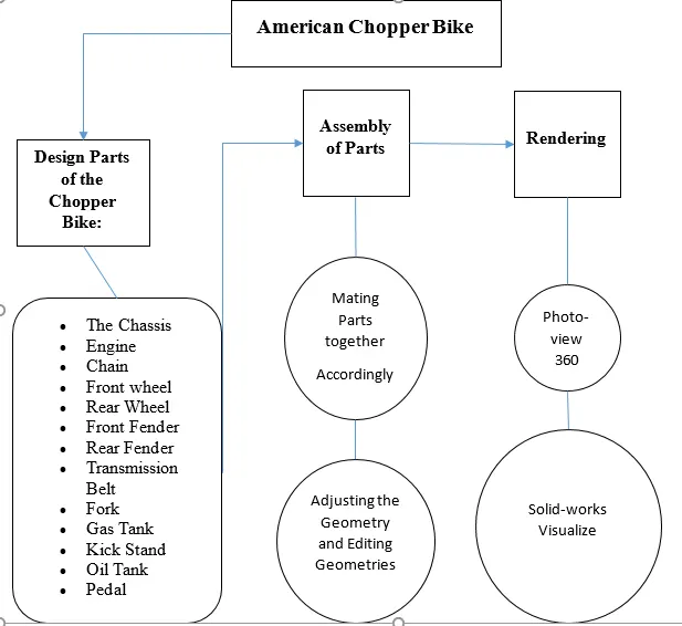
Description
- Part Design:
The Chassis:
This Part serves as the referrence / Frame of the Chopper Bike. All other Part is assembled to the Chassis (Using the Axis of the Chassis as a reference). Hence, the chasis was desined with referance to the standard Planes as well as assemby Planes.
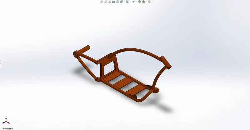
Figure 1: An Isometric View of the Chassis.
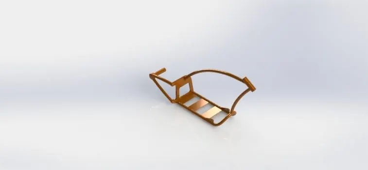
Figure 2: A Rendered View of the Chassis.
Features Used in the Chassis Design
After making Sketches on the Planes, the following features is used to Covert the Sketch to 3D.
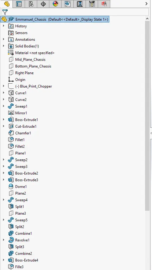
Figure 3: The Feature Tree of the CHASSIS
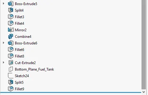
Figure 4: Continuation of the Feature tree Chassis
The Engine:
This is where Power is generated in the Bike. It is Mounted in the Chassis.
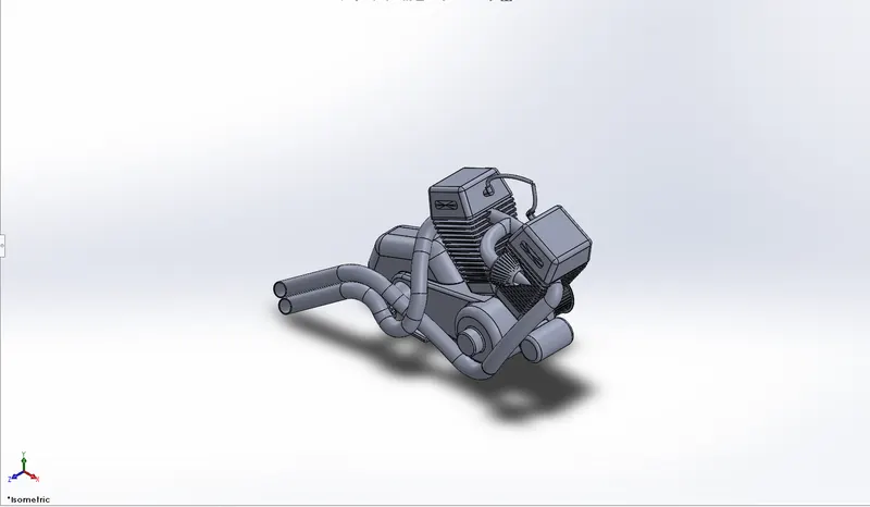
Figure 5: An Isometric View of the Engine
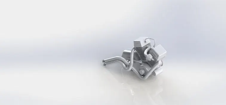
Figure 6: A Rendered View of the Engine
Feature Tree Of the Engine
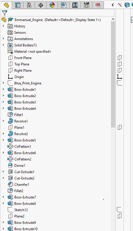
Figure 7: The feature tree of the Engine
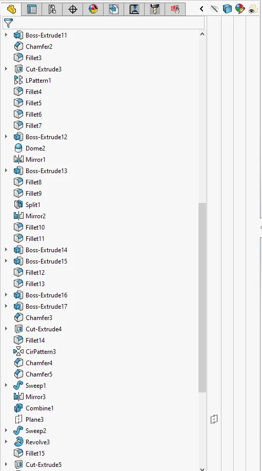
Figure 8: The feature tree of the Engine Continues
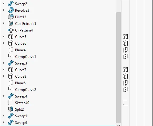
Figure 9: The feature tree of the Engine Ends
With the majority of the Features being used in the Engine and Chassis, A description of individual features incude:
Sketch: This is a feaature used to make drawings in a plane. However, Sketches could be made in a combination of planes using the CompCurve Feature.
Boss-Extrude: This converts a 2-d Sketch to 3-d By giviing it a defined Length in the none Sketch Plane
Cut-Extrude: Is a feature used to Extract parts from a body with reference to the Sketch made on a plane or on the surrface of the Body.
Revolve: This feature is used to make cylindriccal curves as observed in the Chassis
Other Features include the Sweep, Chamfer, fillet, mirror Pattern. The list Goes on as solidworks is freqquently updaated to make Design Much easy.
The Fork:
This part is Attached to the Chassis and it holds the front Tyres and Lights.
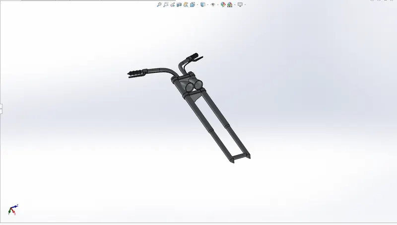
Figure 10: A View of the Chassis.
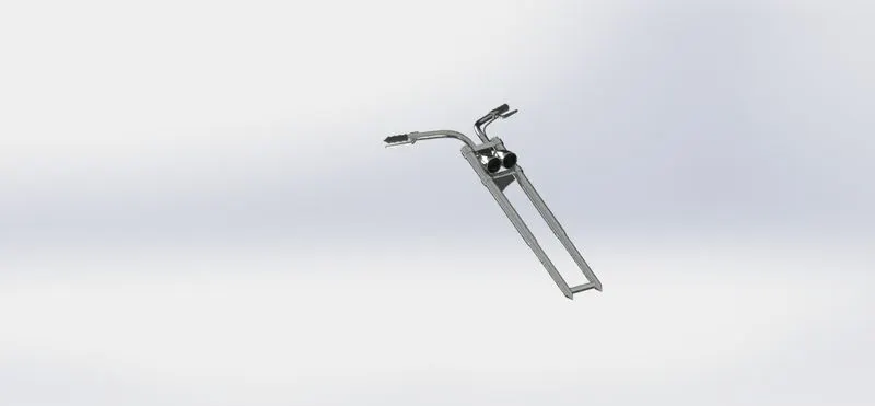
Figure 11: Rendered View of the Fork
Front Wheel:
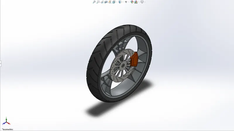
Figure 12: Front_Wheel
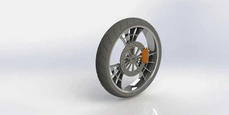
Figure 13: Rendered View
Rear Wheel:
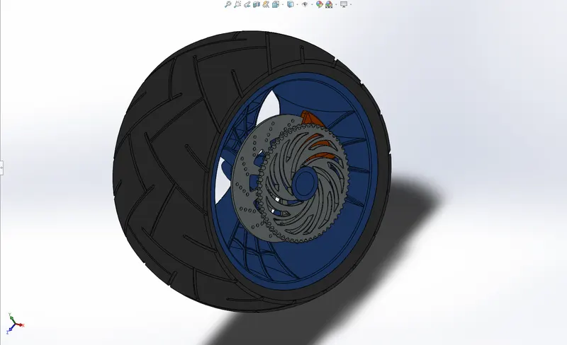
Figure 14: Rear Wheel
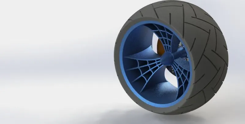
Figure 15: Rendered Rear Wheel
Front Fender:
This Part Covers the Front wheel, Protecting the bike aand rider from Dust and pebbles emmited as a result of the tyres contact with the Ground While riding.
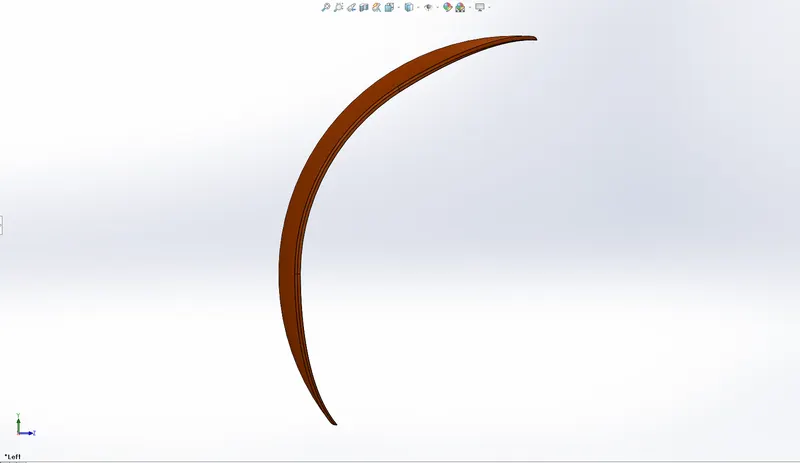
Figure 16: Front Fenders

Figure 17: Rendered Front Fender
Rear Fender:
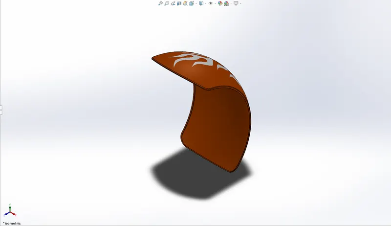
Figure 18: Rear Fender
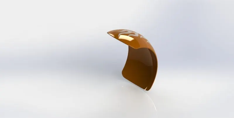
Figure 19: Rendered Rear Fender
The Chain:
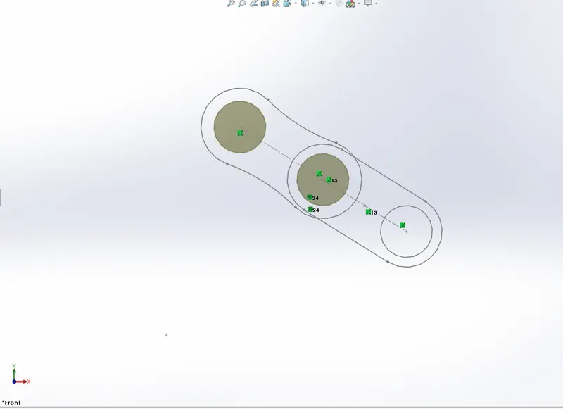
Figure 20: Chain Blocks
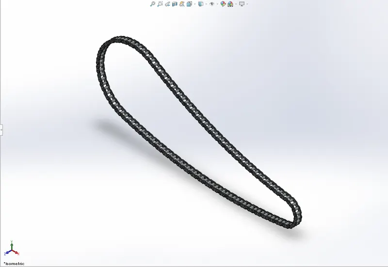
Figure 21: The Chain
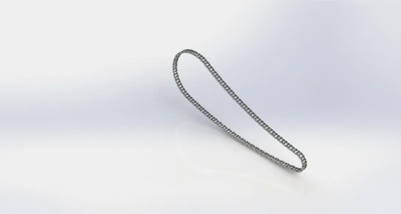
Figure 22: Rendered Chain View
Transmission Belt:
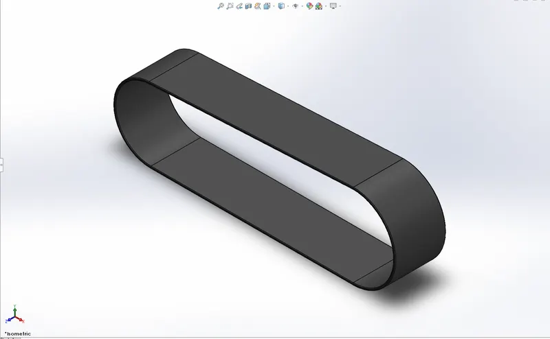
Figure 23: Transmission Belt
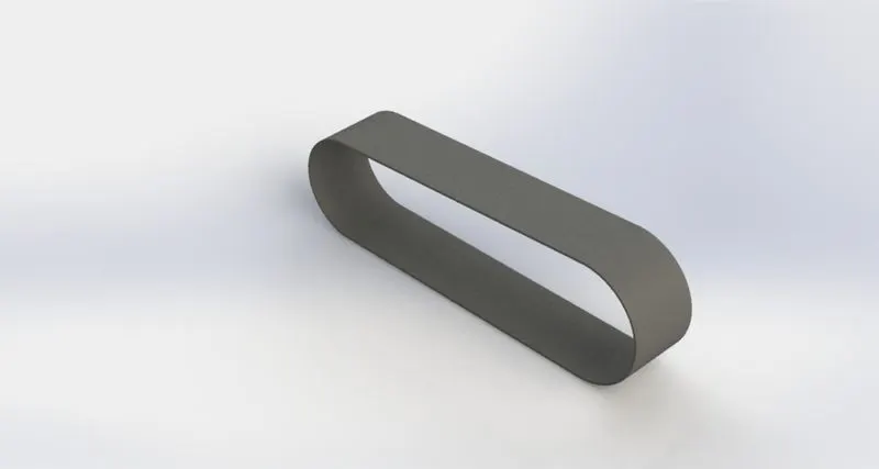
Figure 24: Rendered Transmission Belt
Oil Tank:
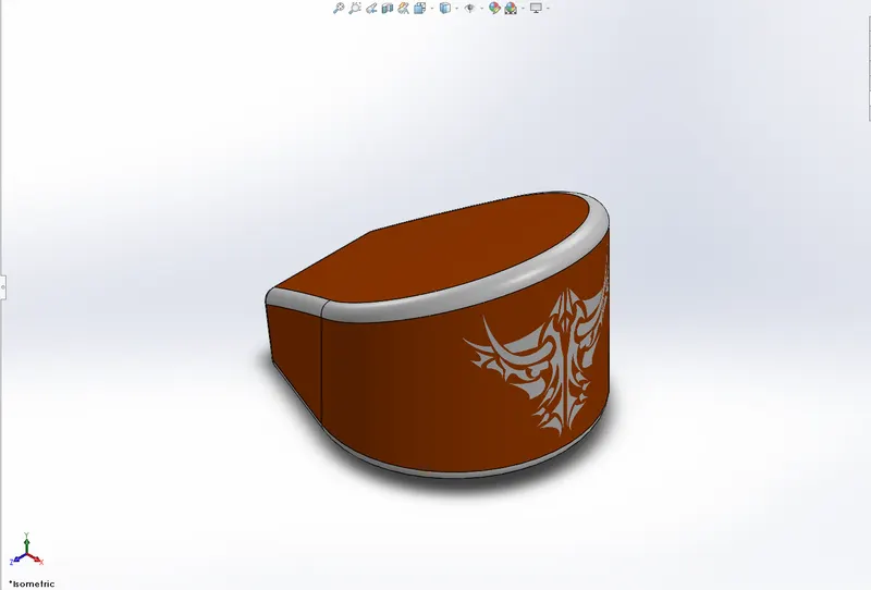
Figure 25: Oil Tank
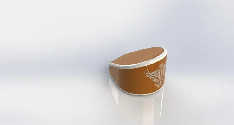
Figure 26: Rendered Oil Tank
Kick Stand:
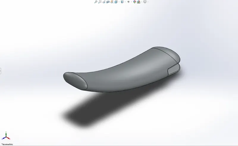
Figure 27: Kick Stand
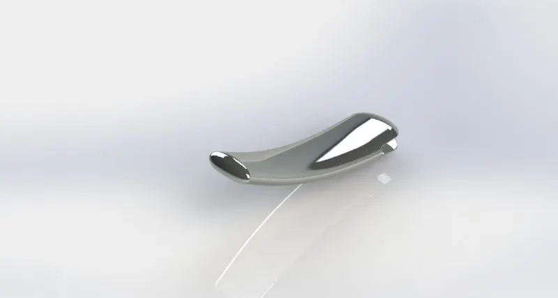
Figure 28: Rendered Kick Stand
Pedal:
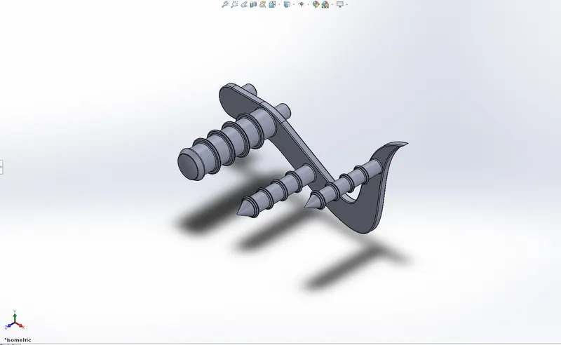
Figure 29: Pedal
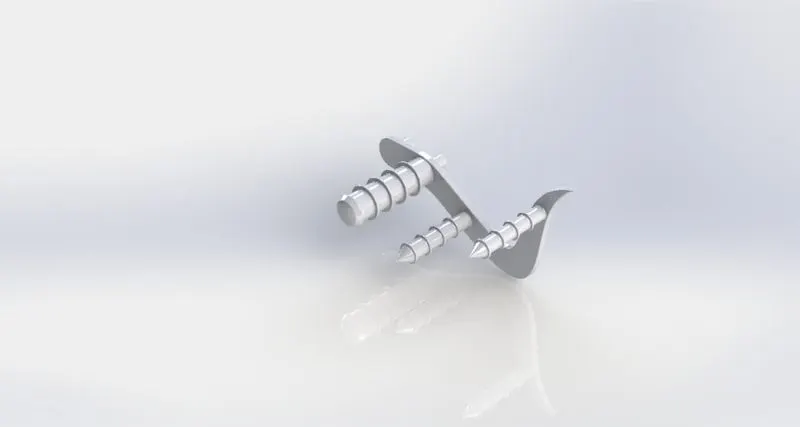
Figure 30: Rendered Pedal
Gas Tank:
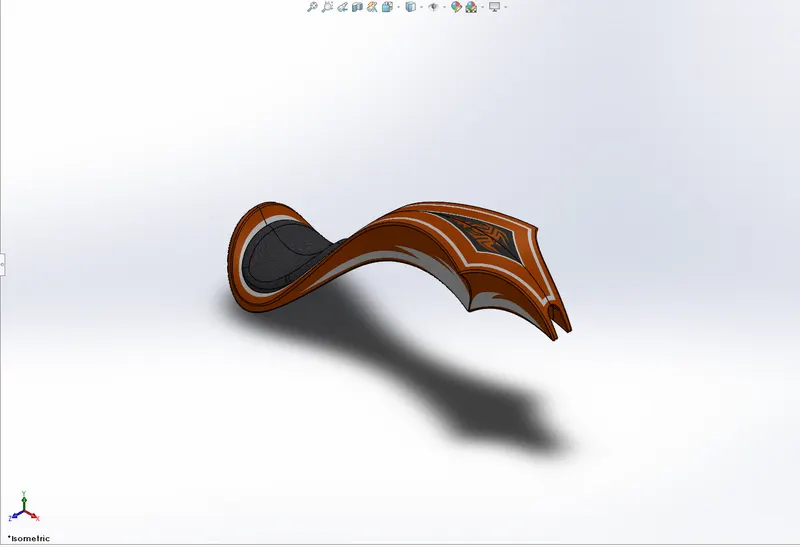
Figure 31: Gas Tank
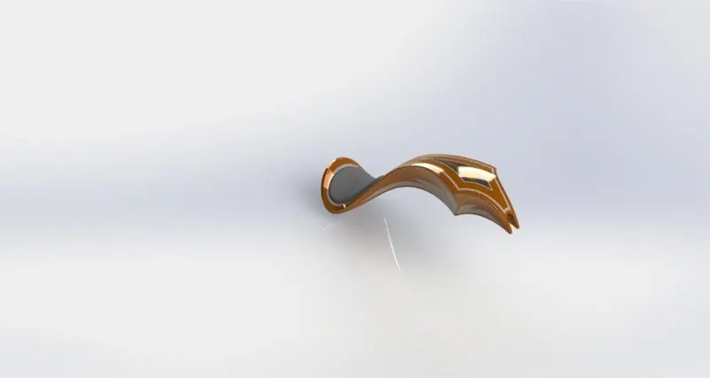
Figure 32: Rendered Gas Tank
2. Assembly
All Individual Parts were put together and Edited using the Mate Feature
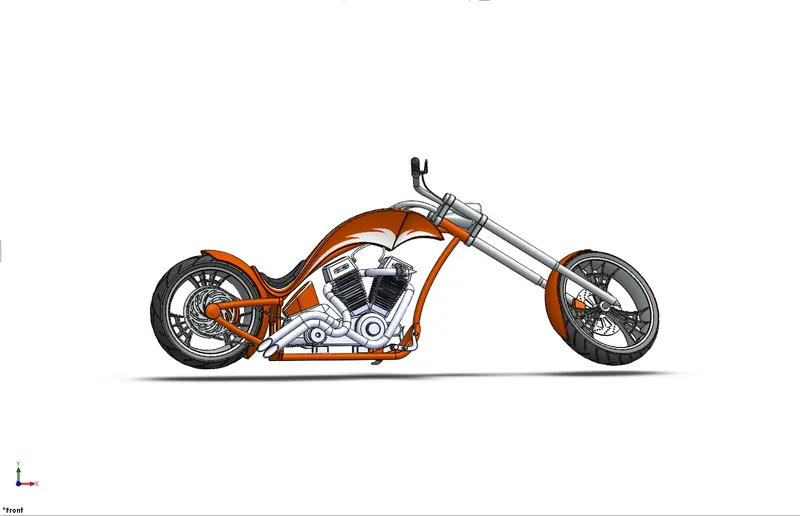
Figure 33: Front View of the assembly
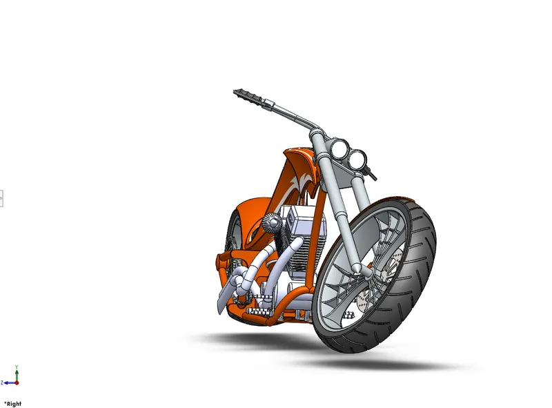
Figure 34: Right View of the assembly
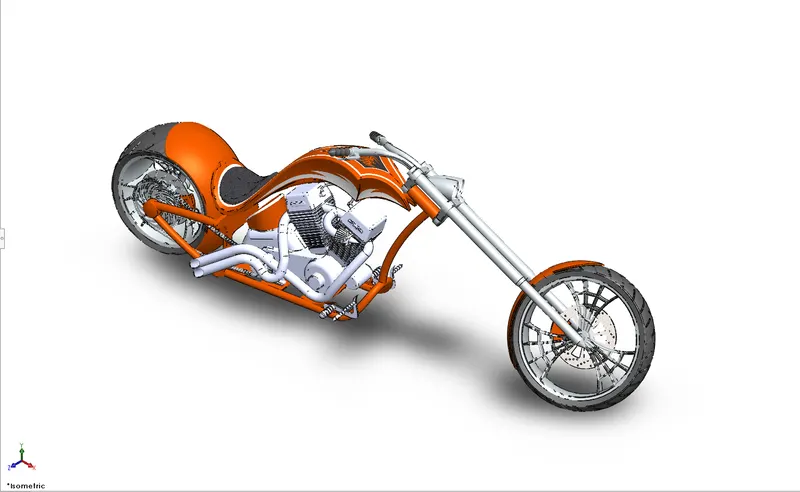
Figure 35:Isometric View of the Assembly
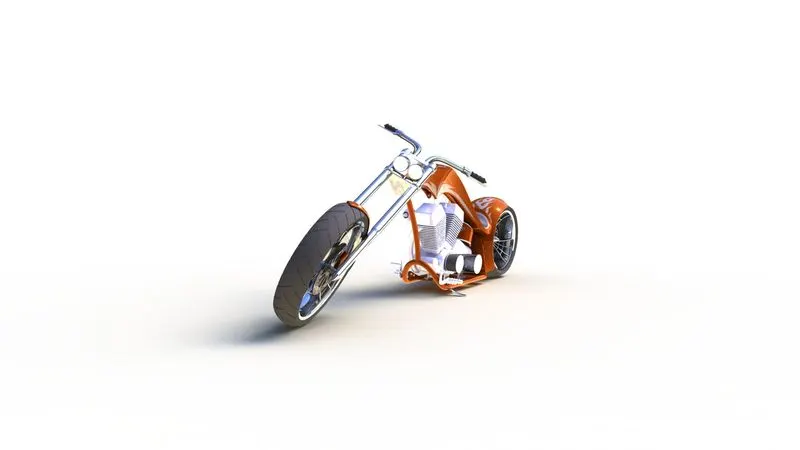
Figure 36: Rendered Final Assembly
Rendering
Rendering or image synthesis is the process of generating a photorealistic or non-photorealistic image from a 2D or 3D model by means of a computer program. The assembled model was first prepared for rendering by:
- Making sure the chooper bike sits properly on th plane
- Creating a cameera view for thee bike
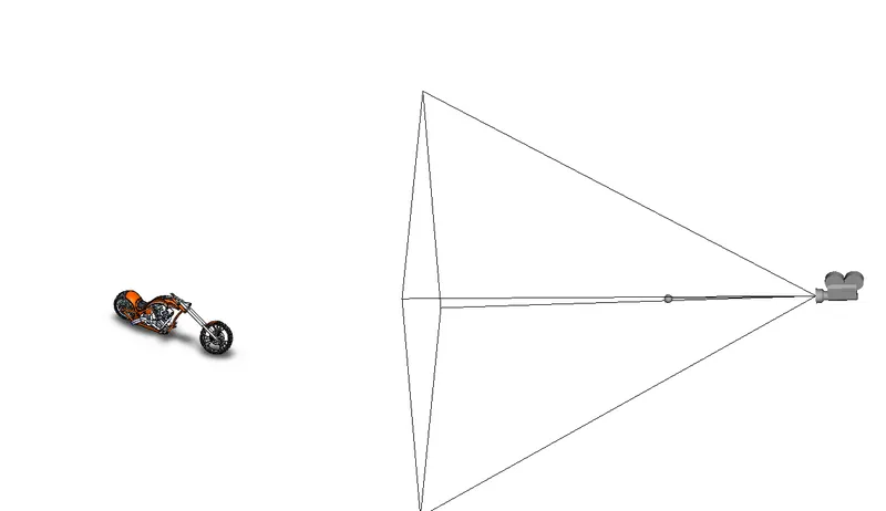
Figure 37: View Showing the Camera set up
Rendering Was Done Using Photo-view 360.
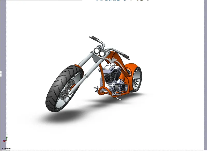
Figure 38: Camera view of the Chopper Bike
Color can also be Adjusted After rendering
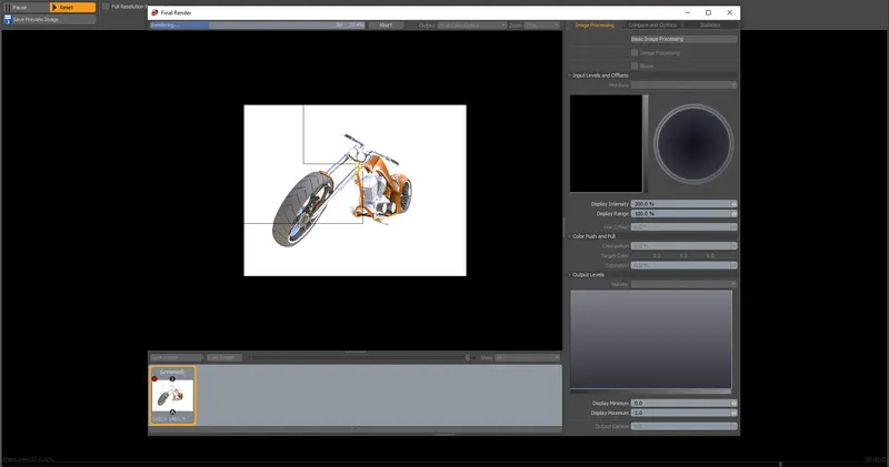
Figure 39: Showing the Final Rendering Process
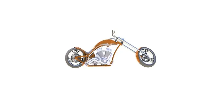
Figure 40: Front View Render
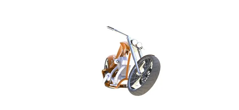
Figure 41: Right View Render
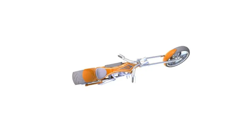
Figure 42: Top View Render
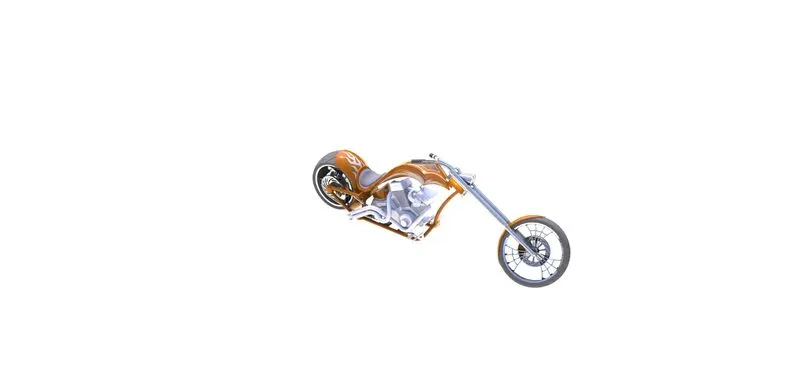
Figure 43: Isometrric View Render
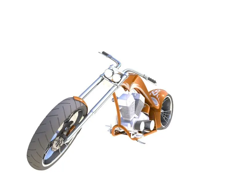
Figure 44: Camera View Render
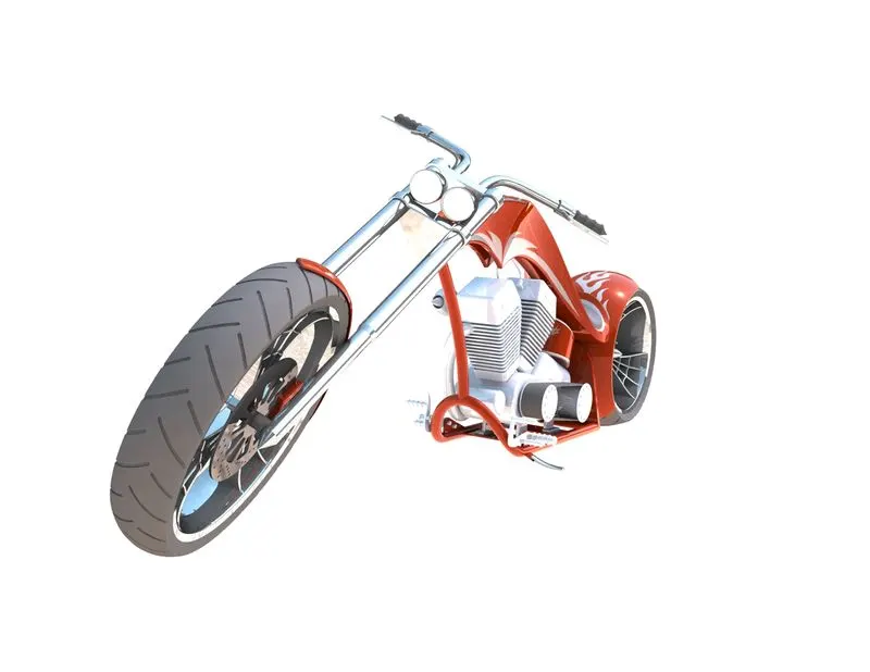
Figure 45: Final Render
Solid works Visualize is also used to carry ourt renders. SOLIDWORKS Visualize enables you to use your 3D CAD data to quickly and easily construct photo-quality material, ranging from pictures to videos, interactive online content, and immersive Virtual Reality. Let the products come to life.
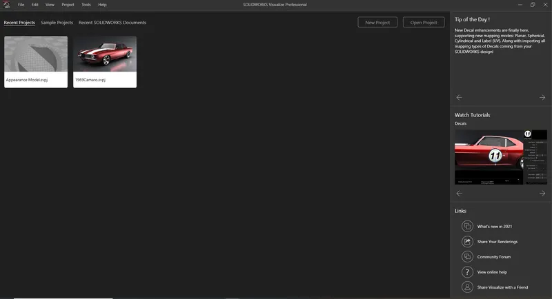
Figure 46: A view of Solid works Visualize.
Conclusion
This Project Made etensive use of the Solid woorks software and Gave an insight of how complex shapes and Bodies ccan be designed. Studying the soft copy of the Chopper bike deesign will give a good insight on features Available in solid works. It is recommended in Industries to make design Easy.