Radar Mast & Final Assembly of Yacht
|
MODELING OF SUNSEEKER (YATCH) ON SOLIDWORKS |
INTRODUCTION:
In this project we are to learn the entire modeling of an American chopper on solid works and solid works visualize.
The different components of the motorcycle we deal with are:
- Propeller
- Radar
- Blueprints
- Hull
- Garage
- Seating arrangements
- Super Structure
- Radar Mast
After designing the part components, we have worked upon the assembly and the photo rendering of the chopper which gives it a complete and realistic view.
DESIGN APPROACH:
Starting with the transmission belt and ending till the rendering section has been described step by step by means of a flow chart.
|
Propeller |
|
Hull |
|
Seating Arrangements |
|
Super Structure |
|
Assembly |
|
Rendering |
|
Radar Mast |
|
Back seats |
|
Front seats |
|
Radar |
|
Garage Door |
Let’s discuss what are the features and properties used in the entire model to design different parts:
- Extrude Boss: The Extruded Boss is the most basic of all SOLIDWORKS features and extrudes a sketch along a straight-line path to add material. As a sketched feature, it requires a sketch before use.Once the sketch has been created, exit the sketch and select the Features tab of the Command Manager. Then, click the Extruded Boss/Base command. If a yellow dialog box appears in the Property Manager asking you to create a new sketch, don’t worry – simply click on the sketch in the graphics area to use it for the feature. The Property Manager for the Extruded Boss allows you to control starting location, extrude depth and draft for the feature, among several other parameters:
- Fillet: Fillets are classified as applied features, and as such do not require a sketch to be used. Fillets serve to round off edges and/or corners by adding or removing material, depending on whether the edge is internal or external. It should be noted that fillets of different sizes must be created as separate features. Typically, it is best practice to create the largest fillets first and follow with smaller fillets.
- Revolved Boss Feature: Adds material by revolving a sketch around an axis. Remember, once geometry has been created in your model, any flat face can be used as a sketching surface. It is very important to draw an axis in the sketch which needs to be revolved.
- Extrude Cut: Similar to the extrude boss feature this feature needs a sketch on the solid body which needs to be cut and the desired shape is then cut off.
- Shell: SolidWorks shell tool is mainly used for shelling process, in which the material removed from the inner body of model by keeping small thickness and results a hollow model. Using this tool, you can make either completely closed hollowed model or one face opened type.
- Sweep Boss / Sweep Cut: Sweep creates a base, boss, cut, or surface by moving a profile (section) along a path, according to these rules: The profile must be closed for a base or boss sweep feature; the profile may be open or closed for a surface sweep feature.
- Loft Boss/ Loft Cut:The loft feature is an important tool for (surface) modelling in SolidWorks. The loft feature creates a shape by making transitions between multiple profiles and guide curves. This tool is very valuable for modelling complex surfaces. You can do some cool stuff when you use this feature properly.
- Linear Pattern: You can use linear patterns to create multiple instances of one or more features that you can space uniformly along one or two linear paths.Pattern instances inherit the visual properties of the original feature when you select Propagate Visual Properties in the Property Manager.
|
Seed feature |
Linear pattern - two directions |
|
Linear pattern - one direction |
Linear pattern - two directions Pattern seed feature only in Direction 2 |
- Mirror: Creates a copy of a feature, (or multiple features), mirrored about a face or a plane. You can select the feature, or you can select the faces that comprise the feature.Bodies to Mirror: Select a body in a single model or multibody part to create a mirror entity.Multibody parts: Apply features to one or more multibody partsby selecting Geometry Pattern and using Feature Scope to choose which bodies should include the feature.
- Reference Geometry:Reference geometry defines the shape or form of a surface or a solid. Reference geometry includes items such as planes, axes, coordinate systems, and points. You can use reference geometry in the creation of several kinds of features. For example:
- Planes are used in lofts and sweeps.
- An axis is used in a circular pattern.
- Projected Curve:You can project a sketched curve onto a model face to create a 3D curve. You can also create a 3D curve that represents the intersection of two extruded surfaces generated by creating sketches on two intersecting planes. You can create multiple closed or open-contour projected curves from a single sketch. You can also use 3D sketches as input for the Projected Curve tool. Note: the Projected Curve tool does not support projections of intersecting curves.
- Mate :Mates create geometric relationships between assembly components. As you add mates, you define the allowable directions of linear or rotational motion of the components. You can move a component within its degrees of freedom, visualizing the assembly's behaviour.
Some examples include:
- A coincident mate forces two planar faces to become coplanar. The faces can move along one another but cannot be pulled apart.
- A concentric mate forces two cylindrical faces to become concentric. The faces can move along the common axis but cannot be moved away from this axis.
Mates are solved together as a system. The order in which you add mates does not matter; all mates are solved at the same time. You can suppress mates just as you can suppress features.
- SURFACE FEATURE TAB: Surface Modelling is a method used to create and represent complex shapes with high curvature controls. Generally, surfaces are used as an alternative where a particular feature is difficult to create using solid modelling. It is helpful especially in applications like centrifugal pumps, Organic shapes, Car body panels, Boat Hulls, etc., Continuity between the curves is very important for aesthetic reasons. NURBS (Non-Uniform Rational B-Spline) curves are widely used. SOLIDWORKS surface uses a parameterized mesh of curves ( U-V curves). The face curve option available to capture a curve from the surface.
Now that we have discussed all the features that are used in designing of the SUNSEEKER lets actually see how it was designed.
- Propeller: To design this part we start with a sketch on the Right plane and using the revolve feature we design the base of the propeller, followed which we started making the design of the fan and applying some fillets to the parts at the end the sigle blade of the fan was put through a circular pattern to make 6 instances.
- Radar: Radar is a very simple geometry which is basically made from a extrude boss feature we start by designing the model in half and mirroring it midway so that we don’t have to repeat the entire process twice such as the bolts at the end of the radar, this has been the theme of the project we will be modeling half the design and follow it with a mirror to save time. We have used the text tool here to imprint the name in the radar.
- Blueprint Setup: One of the most important part of any designing is the set up of the blueprint. Blueprint is a layout of the end product, giving us the idea of what we are working and matching it to the end goal. Here in this we fix our layouts from the top, bottom, side, front and back view in addition to that we add a couple of planes so that we will have perfect view of what we are working on.
- Designing of Hull: This is far most the most important thing in the entire design; it is the base of the entire yatch basically the structure of it. We start it by designing two curves and using the surface loft to get the base of the hull, a point to note down is that we again design it in halves and mirror the other half, the first surface loft is followed by another loft to get the side part of the hull followed by another to pen down the back and surface extrude to get the base and three parts to join in together, then we knit them to make a single surface body we use the fill feature to fully cover the edges and them shell it out to a hollow hull base. Now we extrude the certain parts to put the flooring and the back stairs and garage doorway. Now we design the windows and the small holes on the side of the hull by adding a plane and sweeping the feature, now comes the part where we start designing the front portion of the hatch and parts besides it the rope holders and rest of the anchor parts. For designing that we go step by step using the blueprint sketching the appropriate geometry and then followed by the extrude and the sweep features as demanded according to the design.
Which is followed by the railing section which is again done by making a projected curve with two sketches and then sweeping it all the way making some geometrical changes as seen in the figure,
Now we start sketching the geometry required for the propeller projector and the base of it at the backplane with help of extrudes and chamfers features in addition with some revolve and mirror of the part we make the design as shown in the diagram.
in addition to this with help of linear pattern feature we design the same and arrange everything accordingly as our blueprint. After which we start the designing of the main anchor part again we divide it into two halves design the first side and mirror it accordingly we do this by adding a new plane and start the drawing on the side face of the hull the sketch is extruded out and designed accordingly with the help of the chamfer feature we get to maintain the dimensions and the geometry of the part.
Now we start the designing of the garage which we do by splitting the extruded part of the hull and applying cut extrude feature now that we have successfully completed the required parts of the hull we save the part of the garage split and use that surface in the making of the garage door. Now we create a deck surface which we will use for the making of super structure (cabin) and the seating arrangement of the yatch. After this we mirror the entire design through the mid plane to complete the structure of the hull.
For the appearance part we use the decals on the floor of the surface and the stairs of the hull we paint the entire structure white with shades of navy blue and give the windows the glass appearance make the required changes with the parts and provide them with the material needed.
- Garage Door: As we had already saved the split part from the hull design we open that part and perform a cut extrude shell the part which is not required and the design the bolts at the side of the doors as we had the geometry already fixed this was not a big deal we give the name of the yatch at the back of the door.
- SEATING ARRANGEMENT: The arrangement is made on the surface which we had already created while designing the hull which is going to be the base of our arrangement. We do it in three different parts front, middle and the rear seats all designed one after another.
- Front Seats: we start by sweeping the layout of the seat and again will be mirroring the parts by designing one side, we make the layout trim the exteriors and fill the part, then design the geometry of the seats and revolve them to get the seats and then mirror it along one by one to get the seats and the sides as per as required in the blueprint.
- Middle Seat: We start the designing by making the base of the arrangement and extrude it all the way to make a sofa seating arrangement a center table and following the same mirror concept and division of the seats as we did it in the first part we design the middle seats.
- Rear Seats: We start by creating a sketch on the deck surface from the hull part and sweep it above to make the desired structure the design of the rear seat is quite complicated and certain sweeps and extrudes has been used as required. This is a little different from the above two and we also make the side rails and the flag in this part.
- SUPER STRUCTURE: This being the cabin of the yatch which also has the cockpit included in it. This design is included with stairs, Jacuzzi, rear doors, front windshield, wipers, the base of the radar and on all top of that the main structure of the cabin with windows. We again design the half of the structure and replicate the other half on the mid plane to get the complete design of the cabin. We start of by displaying the top view and the side view of the blueprint and then it is followed by sketching on the deck surface, the main reason to sketch on the deck surface is that it will save time in assembly and then we don’t have to put any Mate relations between them as it has already been designed in such a manner and accuracy. After sketching the base of the super structure we design the wings like body of the structure as shown in the image.
The we start lofting the surfaces and joining it to give the proper structure and curves of the structure according to the blueprint some cuts and trims are performed most of the things are done by creating surfaces and not solid bodies the surfaces are knit and merged together because of which the sketches being precise to the dimensions. A point to remember is that if the surface when knit have blue edges then the surface are not merged properly and need some dimensional changes or reforms in the sketch.
After laying out this from the top plane we start the sketch of the front part of the cabin the face and the part with the Jacuzzi and stairs. We start drawing circles and lofting them for Jacuzzi and the front part is made with the sketch of some conventional no midpoint splines again we have to be very precise with the dimensions.
Now we work on the details of the design the upper cuttings, trimming and shaping of the edges, fillets and chamfers but the most important of all creating the base for our radar mast. Mostly all of these features are carried on the top view of the cabin.
Now that we have done and achieved the desired design we move to our last step of mirroring the entire structure to the mid plane but ahead of that we need to make wipers which are designed by simple boss extrude and some chamfers with a sweep between both to connect. The final structure of the part is ready. For the appearance we design some decals for the floors and for the stairs which has been applied granite wall is given to the Jacuzzi and the glasses are made transparent for better visibility.
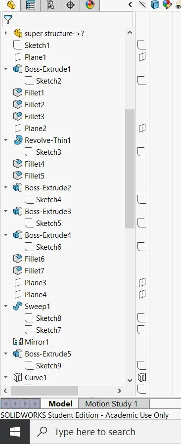
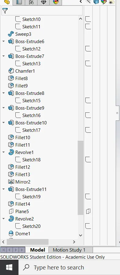
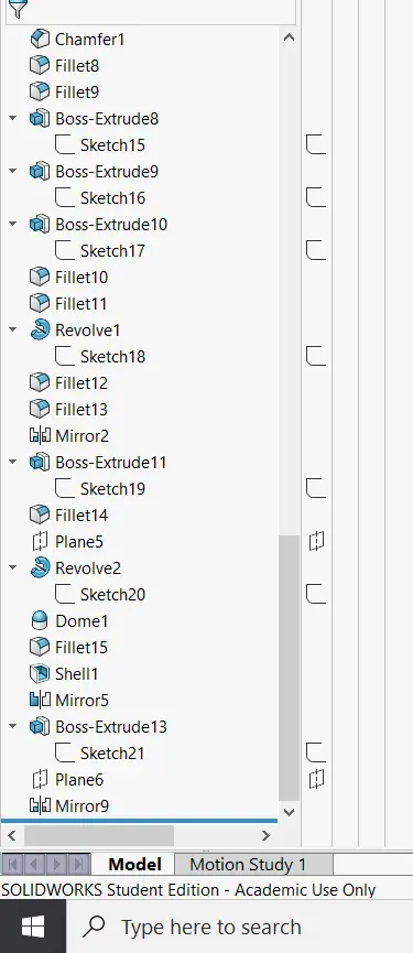
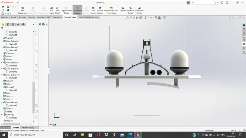
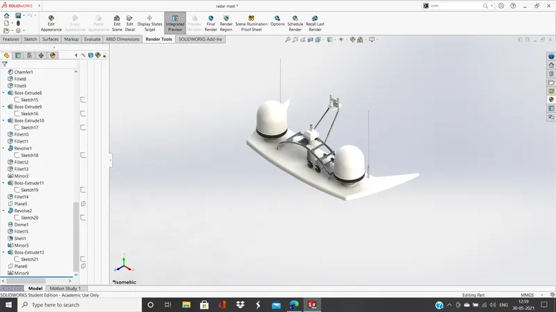
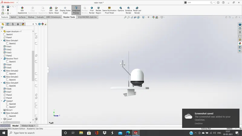
- Radar Mast: in this sketch we have to work with the designing of the antenna and the radio signal wires and the receptors in addition to which we have to make an appropriate base for the Radar to be placed, we stat our fig on the top plane with the help of the blue print design the desired design and then revolve parts to make the wings are made first and used as the base of the entire mast. We the design antennas which is followed by the sweeped curved pattern and the dome like structure is made and attached with the base. Now the entire thing is attached to the additional surface that we had created in the super structure part for the radar mast layout. Now the design is mirrored.
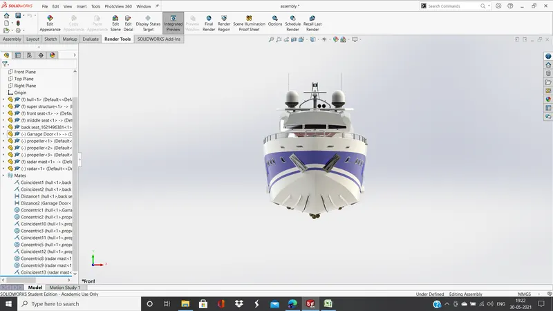
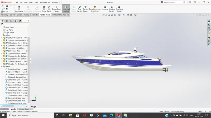
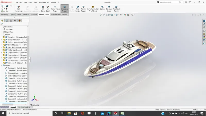
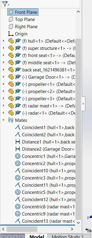
- Assembly: As we have created the base for most of our products or individual parts assembly of these different parts is going to be easy. We start in from bringing the base the hull of the yatch, followed which we bring the superstructure and click ok and as we have planned the body is on top and in perfect position. Then one by in we get in the front and the middle seat as well. Now as we have not designed the backseat with the deck surface we have to apply a coincident mate with the base of the seat and the deck surface now as we desire we create a distance mate with the end edge of the seat and the end of the deck surface plus we align the mid plane of the backseat with the right plane of the hull to get the perfect position. As we bring in the radar mast we see it is directly placed upon its own place. Now we bring in the radar plate to and mate it at the perfect position and align properly with the mast.