Radar Mast & Final Assembly of Yacht
SUNSEEKER PREDATOR YACHT - RENDERING AND ASSEMBLY
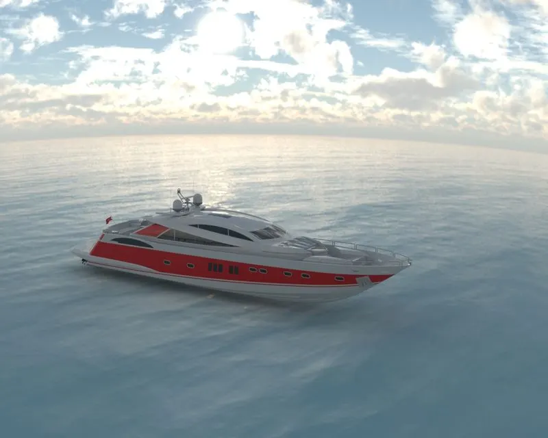
OBJECTIVE
The objective of this project is solely aimed at applying all surface modelling tools in designing a part(s) and
then use the surface as reference to assemble the parts of the Sunseeker Predator Yacht in SolidWorks.
INTRODUCTION
In this project, we will design individual parts of the Sunseeker Predator Yacht in SolidWorks by making use
of various surface modelling tools combined with solid modelling features, projected curves and reference
geometries to eventually mate all the parts using a reference surface to achieve the fully assembled Yacht.
All the sketches used to design the Sunseeker Predator Yacht will be constrained with proper dimensional and
geometrical constraints enabling us to make any variations during the design process. This
technique/approach that we are going to use in this project is called feature-based parametric modelling,
DESIGN APPROACH
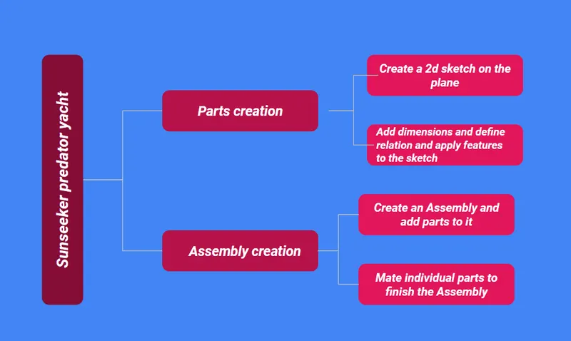
The Parametric feature-based Bottom-up approach has been followed in the modelling of this Sunseeker
Predator Yacht.
Please refer to the Flowchart below:
DESCRIPTION
PROPELLER
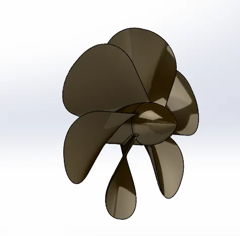
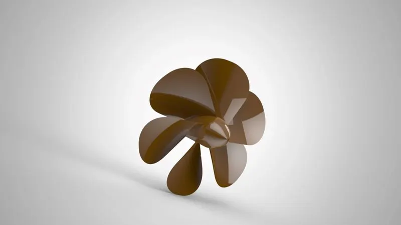
As the name suggests Propeller is a device which propels (drive de push forward) an object that transforms
rotational power into linear thrust by acting upon a working fluid. such as water or air (in this case, water) as
we are creating a Propeller for aur Yacht. The Sunseeker Predator Yacht will be assembled with three
propeller.
Tools/Features used:
1. Revolved Boss/Base: To create a solid feature, a sketch or its selected contours are revolved around an
axis.
2. Lofted Boss/Base: To create a solid feature, it creates parts with variable cross section which are
blended from one section to the other.
3. Fillet: We can apply this as a sketch tool while creating our sketch or as a feature after a 2D sketch is
transformed into a 3D feature. It rounds the corner of two sketch entities at their intersection point creating
a tangent arc. When applied as a 3D feature (solid surface,) it creates a rounded internal or external face
along one or more edges.
4. Extruded Cut: This feature extrudes a sketched profile of a solid model to cut it into one or two directions.
5.Circular Pattern: It creates a pattern of features, faces and bodies around an axis.
RADAR
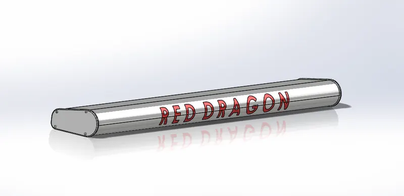
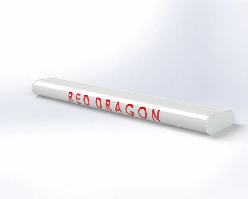
The term Radar was coined as an acronym for Radio Detection And Ranging: Here we are referring to Marine
Radars which are used to detect what objects/obstades are around, seeing through darkness, precipitation
and poor visibility to safely navigate a ship/boat by avoiding collisions. The radar scanner keeps rotating at
360 degrees about its vertical axis and is located at the top of the ship/boat. For our radar we will also create
and add a text on its surface.
Tools/Features used:
1. Extruded Boss/Base: This feature extrudes an entire sketch or its selected contours in one or both
directions (upto a specified distance which can be altered by the user) to give a desired 3D part.
2. Fillet: We can apply this as a sketch tool while creating our sketch or as a feature after a 2D sketch is
transformed into a 3D feature. It rounds the corner of two sketch entities at their intersection point creating
a tangent arc. When applied as a 3D feature (solid/surface), it creates a rounded internal or external face
along one or more edges.
3. Extruded Cut: This feature extrudes a sketched profile of a solid model to cut it in one or two directions.
4. Sketch Driven Pattern: It creates a pattern of features, faces and bodies based on sketch points.
5 Mirror:This can be used as a sketch tool or as a feature. In sketch mode, it mirrors the selected entities
about a reference plane or centerline. When used as a feature on a 3D body, it mirrors the features, faces
and bodies about a face or a plane.
6.Split Line: It projects a sketch to curved or planar faces, creating multiple separate faces.
HULL
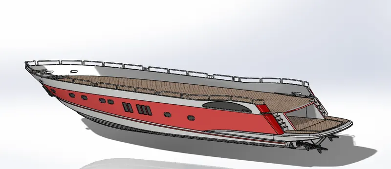
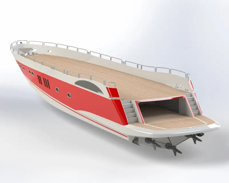
Hull is the watertight enclosure of the watercraft which protects the cargo, machinery, and accommodation
spaces of the watercraft from weather flooding, and structural damage. The Hull which we will be designing
for our Yacht will be fully covered with a deck.
Tools/Features used
1. Projected Curve: Projects a sketched curve onto a face or sketch.
2. Lofted Surface: Creates a lofted surface between two or more profiles.
3. Trim Surface: Trims a surface where one surface intersects with another surface, a plane, or a sketch.
4. Extruded Surface: Creates an extruded surface from the sketch.
5. Knit Surface: Combines two or more adjacent, non-intersecting surface together.
6 Filled Surface: Constructs a surface patch within a boundary defined by existing model edges, sketches,
or curves.
7 Shell: A thin-walled feature is created using Shell which removes material from the selected solid body.
8. Extruded Boss/Base: This feature extrudes an entire sketch or its selected contours in one or both
directions (upto a specified distance which can be altered by the user) to give a desired 3D part.
9. Extruded Cut: This feature extrudes a sketched profile of a solid model to cut it in one or two directions
10. Fillet: We can apply this as a sketch tool while creating our sketch or as a feature after a 2D sketch is
transformed into a 3D feature. It rounds the corner of two sketch entities at their intersection point creating
a tangent arc. When applied as a 3D feature (solid/surface), it creates a rounded internal or external face
along one or more edges.
11. Chamfer: We can apply this as a sketch tool while creating our sketch or as a feature after a 2D sketch
is transformed into a 3D feature. It creates a transitional edge at the intersection of two sketch entities when
used as a sketch tool. When used as a feature, it creates a bevel feature along an edge or a vertex.
12. Plane:A reference plane is added based on the selection of references as per the requirement of our
sketch.
13. Swept Boss/Base: Sweeps a closed profile along an open or closed paths to create a solid feature.
14. Revolved Boss/Base: To create a solid feature, a sketch or its selected contours are revolved around
an axis.
15. Dome: This creates a dome shape to the selected face(s) (planar/non- planar).
16. Helix and Spiral: Acts a helix or spiral curve from a sketched surface.
17. Linear Pattern: creates a pattern of features forces and bodies in one or two linear directions.
18. 3D Sketch: Creates a new sketch in 3D space.
19. Mirror: This can be used as a sketch tool or as a feature. In sketch mode, it mirrors the selected entities
about a reference plane or centerline. When used as a feature on a 3D body, it mirrors the features, faces
and bodies about a face or a plane.
20. Split Line: It projects a sketch to curved or planar faces reality multiple separate faces.
GARAGE DOOR
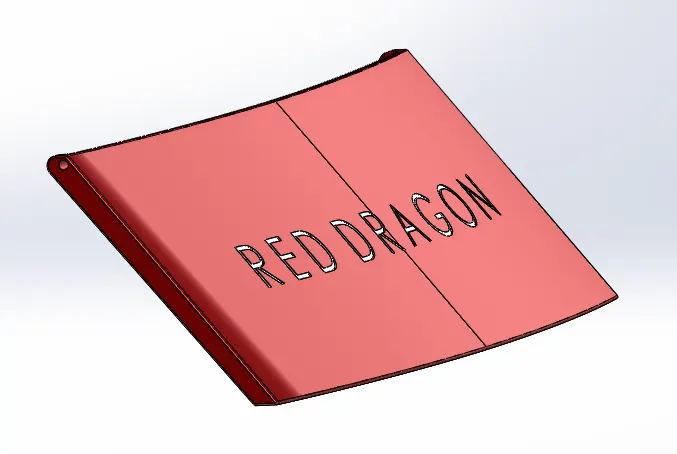
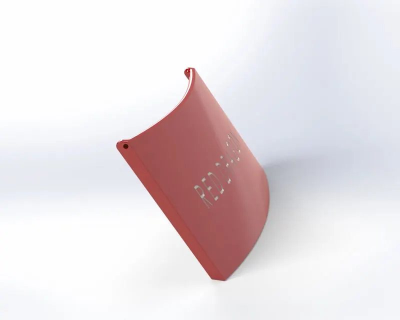
This will be the hydraulic door covering the garage on our Yacht.We also crete and add a text on the surface
of the Garage Door.
Tools/Features used:
1. Extruded cut: This feature extrudes a sketched profile of a solid model to cut it in one or two directions
2. Shell: A thin-walled feature is created using Shell which removes material from the selected solid body.
3. Fillet:We can apply this as a sketch tool while creating our sketch or as a feature after a 2D sketch is
transformed into a 3D feature. It rounds the corner of two sketch entities at their intersection point creating
a tangent arc. When applied as a 3D feature (solid/surface), it creates a rounded internal or external face
along one or more edges.
4. Mirror: This can be used as a sketch tool or as a feature. In sketch mode, it mirrors the selected entities
about a reference plane or centerline. When used as a feature on a 3D body, it mirrors the features, faces
and bodies about a face or a plane.
5.Plane:A reference plane is added based on the selection of references as per the requirement of our
sketch.
FRONT SEAT
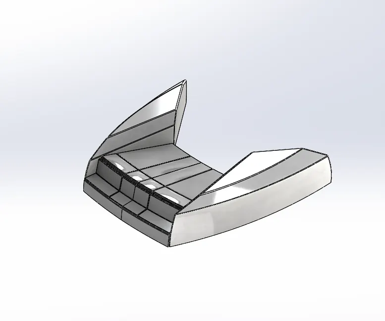
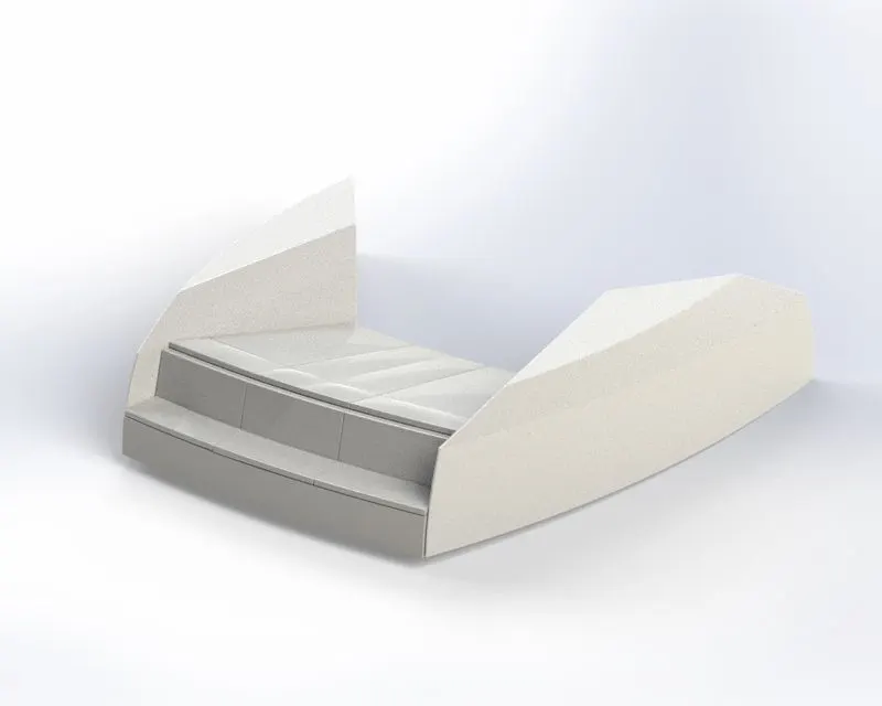
The Front Seat is designed in such a way that it adds to the aesthetic details of our Yacht.
Tools/Features used:
1.Plane: A reference plane is added based on the selection of references as per the requirement of our
sketch.
2.Swept Surface: Creates a surface feature by sweeping an open or closed profile along an open or closed
path.
3.Extruded Surface: Creates an extruded surface from the sketch.
4.Trim Surface: Trims a surface where one surface intersects with another surface, a plane, or a sketch.
5.Filled Surface: Constructs a surface patch within a boundary defined by existing model edges, skeches,
or curves.
6.Lofted Surface: Creates a lofted surface between two or more profiles.
7.Knit Surface: Combines Two or more adjacent non-intersecting surfaces together.
8.Chamfer: We can apply this as a sketch tool while creating our sketch or as a feature after a 2D sketch
is transformed into a 3D feature. It creates a transitional edge at the intersection of two sketch entities when
used as a sketch tool. When used as a feature, it creates a bevel feature along an edge or a vertex.
9. Revolved Bose/Base: To create a solid feature a sketch or its selected contours are revolved around an
axis.
10.Extruded Cut: This feature extrudes a sketched profile of a solid model to cut it in one or two directions
11.Fillet: We can apply this as a sketch tool while creating our sketch or as a feature after a 2D sketch is
transformed into a 3D feature. It rounds the corner of two sketch entities at their intersection point creating
a tangent arc. When applied as a 3D feature (solid/surface), it creates a rounded internal or external face
along one or more edges.
12.Mirror:This can be used as a sketch tool or as a feature. In sketch mode, it mirrors the selected entities
about a reference plane or centerline. When used as a feature on a 3D body, it mirrors the features, faces
and bodies about a face or a plane.
13.Dome: This creates a dome shape to the selected face(s) (planar/non- planar).
MIDDLE SEAT
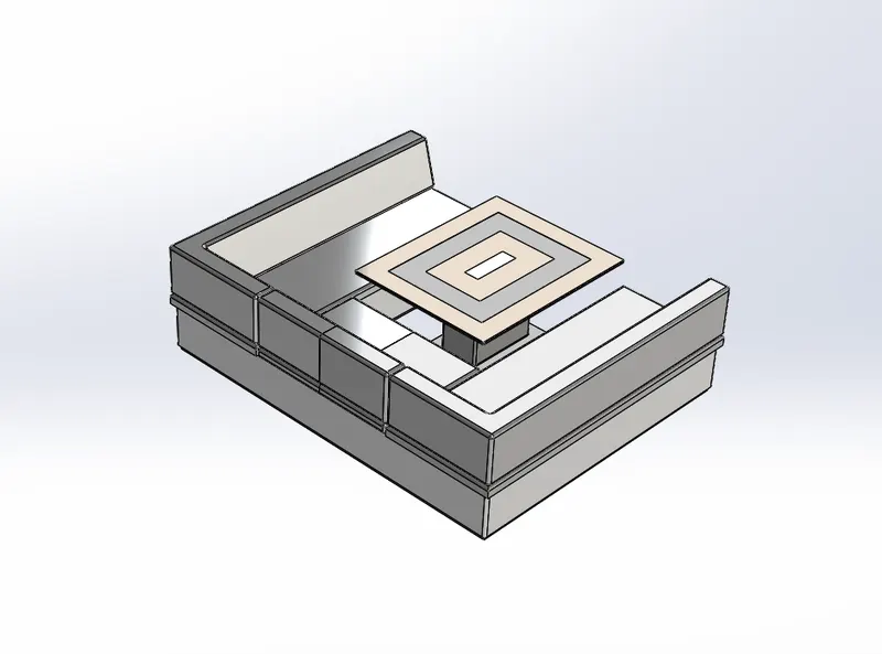
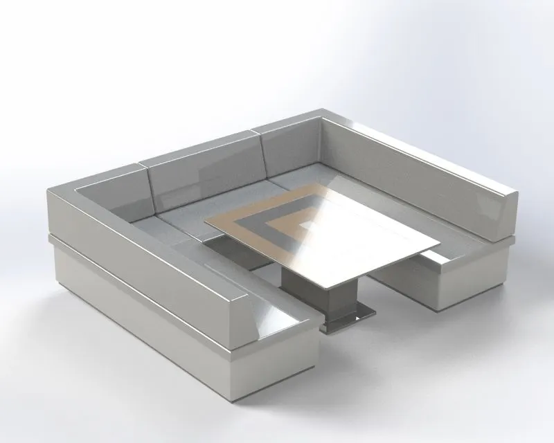
As depicted above the middle seat is provided with a table to conduct meetings on the yacht.
Tools/Features used:
1.Extruded Boss/Base:This feature extrude an entire sketch or its selected contours in one or both
directions (upto a specified distance which can be altered by the user) to give a desired 3D part
2.Plane: A reference plane is added based on the selection of references as per the requirement of our
sketch.
3.Chamfer:We can apply this as a sketch tool while creating our sketch or as a feature after a 2D sketch
is transformed into a 3D feature. It creates a transitional edge at the intersection of two sketch entities when
used as a sketch tool When used as a feature, it creates a bevel feature along an edge or a vertex.
4.Fillet: We can apply this as a sketch tool while creating our sketch or as a feature after a 2D sketch is
transformed into a 3D feature. It rounds the corner of two sketch entities at their intersection point creating
a tangent arc. When applied as a 3D feature (solid/surface), it creates a rounded internal or external face
along one or more edges.
5.Mirror: This can be used as a sketch tool or as a feature. In sketch mode, it mirrors the selected entities
about a reference plane or centerline. When used as a feature on a 3D body, it mirrors the features, faces
and bodies about a face or a plane.
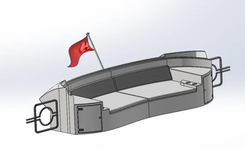
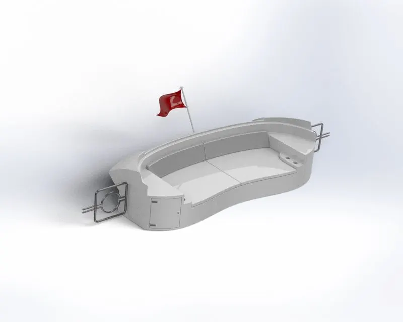
REAR SEAT
Tools/Features used:
1.Plane: A reference plane is added based on the selection of references as per the requirement of our
sketch.
2.Swept Surface: Creates a surface feature by sweeping an open or closed profile are an open or closed
path.
3.Offset Surface: Creates offset surfaces use one or more joining faces.
4.Trim Surface: Trims a surface where one surface intersects with another surface, a plane, or a sketch.
5.Ruled Surface: Inserts ruled surfaces from edges.
6.Knit Surface: Combines two or more adjacent, non-intersecting surfaces together.
7.Lofted Surface: Creates a lofted surface between two or more profiles.
8.Extruded Surface: Creates an extruded surface from the sketch.
9.Extend Surface: Extends the edge. multiple edges or the face on a surface, based on end conditions and
extension type.
10.Combine: This feature combines two or more solid bodies together.
11.Extruded Cut: This feature extrudes a sketched profile of a solid model to cut it in one or two directions.
12. Chamfer: We can apply this as a sketch tool while creating our sketch or as a feature after a 2D sketch
is transformed into a 3D feature. It creates a transitional edge at the intersection of two sketch entities when
used as a sketch tool When used as a feature, it creates a bevel feature along an edge or a vertex.
13. Extruded Boss/Base: This feature extrudes an entire sketch or its selected contours in one or both
directions (upto a specified distance which can be altered by the user) to give a desired 3D part.
14.Fillet:We can apply this as a sketch tool while creating our sketch or as a feature after a 2D sketch is
transformed into a 3D feature. It rounds the corner of two sketch entities at their intersection point creating
a tangent arc. When applied as a 3D feature (solid/surface), it creates a rounded internal or external face
along one or more edges.
15.Mirror: This can be used as a sketch tool or as a feature. In sketch mode, it mirrors the selected entities
about a reference plane or centerline. When used as a feature on a 3D body, it mirrors the features, faces
and bodies about a face or a plane.
16.Revolved Boss/Base: To create a solid feature, a sketch or its selected contours are revolved around an
axis.
SUPERSTRUCTURE
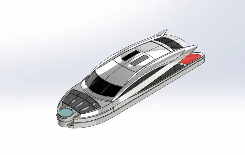
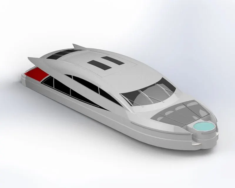
Superstructure means to add a construction to an already existing structure In ships, this is the name given to the part of the ship that emerges from the deck.
Tools/Features used:
1.Extruded Surface: Creates an extruded surface from the sketch.
2.Plane: A reference plane is added based on the selection of references as per the requirement of our
sketch.
3 Swept Surface: Creates a surface feature by sweeping an open or closed profile along an open or
closed path
4. Knit Surface: Combines two or more adjacent, non-intersecting surfaces together.
5.Fillet:We can apply this as a sketch tool while creating our sketch or as a feature after a 2D sketch is
transformed into a 3D feature. It rounds the corner of two sketch entities at their intersection point creating
a tangent arc. When applied as a 3D feature (solid/surface), it creates a rounded internal or external face
along one or more edges.
6.Ruled Surface: Inserts ruled surfaces from edges.
7.Trim Surface: Trims a surface where one surface intersects with another surface, a plane, or a sketch.
8.Projected Curve: Projects a sketched curve onto a face or sketch
9.Lofted Surface: Creates a lofted surface between two or more profiles.
10.Filled Surface: Constructs a surface patch within a boundary defined by existing model edges, sketches, or curves.
11.3D Sketch: Creates a new sketch in 3D space.
12. Extend Surface: Extends the edge multiple edges or the face on a surface, based on end conditions and
extension type.
13.Extruded Boss/Base: This feature extrudes an entire sketch or its selected contours in one or both
directions (upto a specified distance which can be altered by the user) to give a desired 3D part.
14.Extruded Cut: This feature extrudes a sketched profile of a solid model to cut it in one or two directions.
15.Delete Face: Deletes faces from solid bodies to create surfaces, or deletes faces from surface bodies.
16.Offset Surface: Creates offset surfaces using one or more adjoining faces.
17.Thicken: Creates a solid feature by thickening one or more adjacent surfaces which are already knit.
18.Dome: This creates a dome shape to the selected face(s) (planar/non- planar).
19.Split Line: It projects a sketch to curved or planar faces, creating multiple separate faces.
20.Mirror: This can be used as a sketch tool or as a feature. In sketch mode, it mirrors the selected entities
about a reference plane or centerline. When used as a feature on a 3D body, it mirrors the features, faces
and bodies about a face or a plane.
21.Chamfer: We can apply this as a sketch tool while creating our sketch or as a feature after a 2D sketch is
transformed into a 3D feature. It creates a transitional edge at the intersection of two sketch entities when
used as a sketch tool. When used as a feature, it creates a bevel feature along an edge or a vertex.
22.Split: This feature creates multiple bodies from a single body.
RADAR MAST
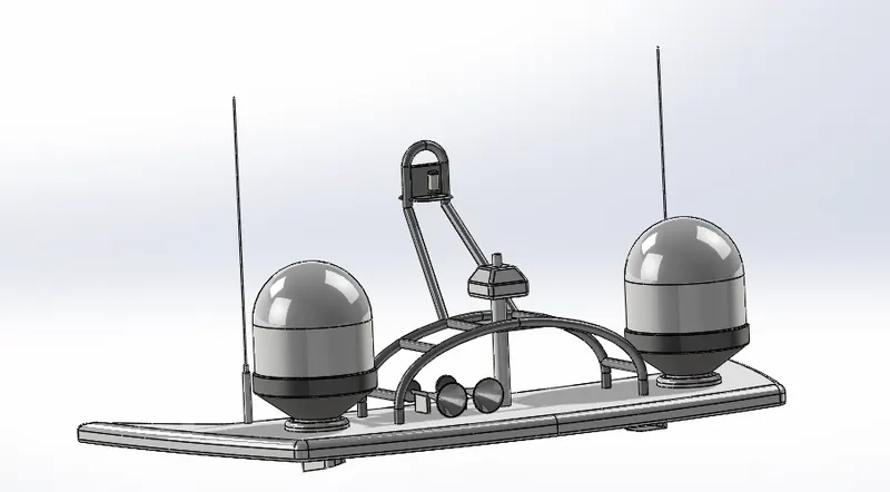
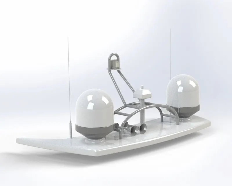
The Radar Mast is at tell pole that holds up the radar on a ship/boat. It consists of a housing that accommodates all major rodas, sensors and antennas.
Tools/features used:
1. Plane: A reference plane is added based on the selection of references as per the requirement of our
sketch.
2.Extruded Boss/Base: This feature extrude an entire sketch or its selected contours in one or both
directions (upto a specified distance which can be altered by the user) to give a desired 3D part.
3.Fillet:We can apply this as a sketch tool while creating our sketch or as a feature after a 2D sketch is
transformed into a 3D feature. It rounds the corner of two sketch entities at their intersection point creating
a tangent arc. When applied as a 3D feature (solid/surface), it creates a rounded internal or external face
along one or more edges.
4.Revolved Boss/Base: To create a solid feature a sketch or its selected contours are revolved around an axis.
5.Swept Boss/Base: Sweeps a closed profile along an open or closed paths to create a solid feature.
6.Mirror: This can be used as a sketch tool or as a feature. In sketch mode, it mirrors the selected entities
about a reference plane or centerline. When used as a feature on a 3D body, it mirrors the features, faces
and bodies about a face or a plane.
7.Projected Curve: Projects a sketched curve onto a face or sketch.
8. Chamfer: We can apply this as sketch tool while creating our sketch or as a feature after a 2D sketch is
transformed into a 3D feature, It creates a transitional edge at the intersection of two sketch entities when
used as a sketch tool When used as a feature, it creates a bevel feature along an edge or a vertex.
9.Dome: This creates a dome shape to the selected face(s) (planar/non- planar).
10.Shell: A thin-walled feature is created using Shell which removes material from the selected solid body.
ASSEMBLY MODEL VIEW IMAGES:
FRONT VIEW
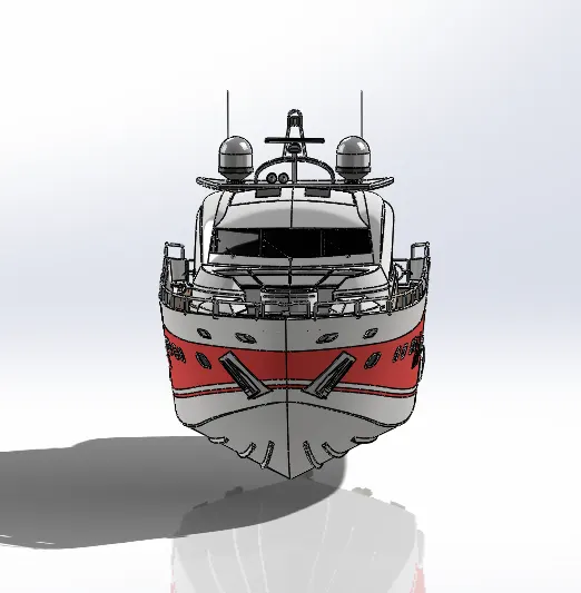
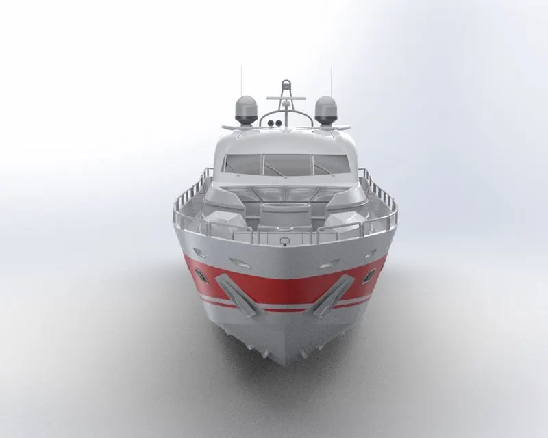
RIGHT SIDE VIEW
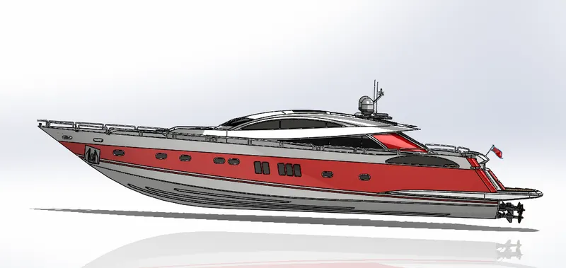
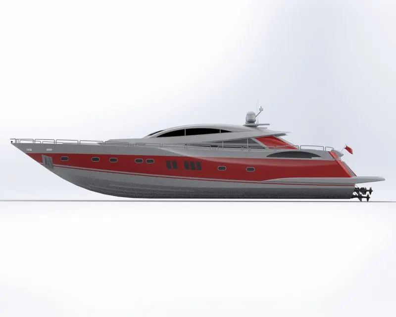
ISOMETRIC VIEW
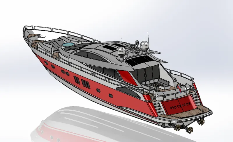
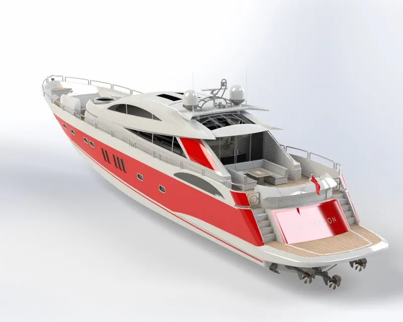
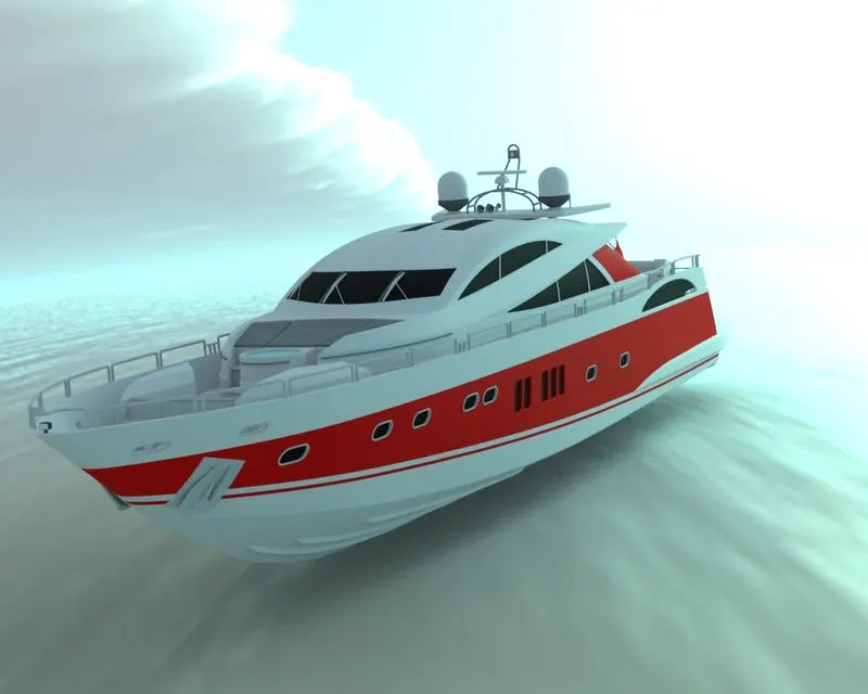
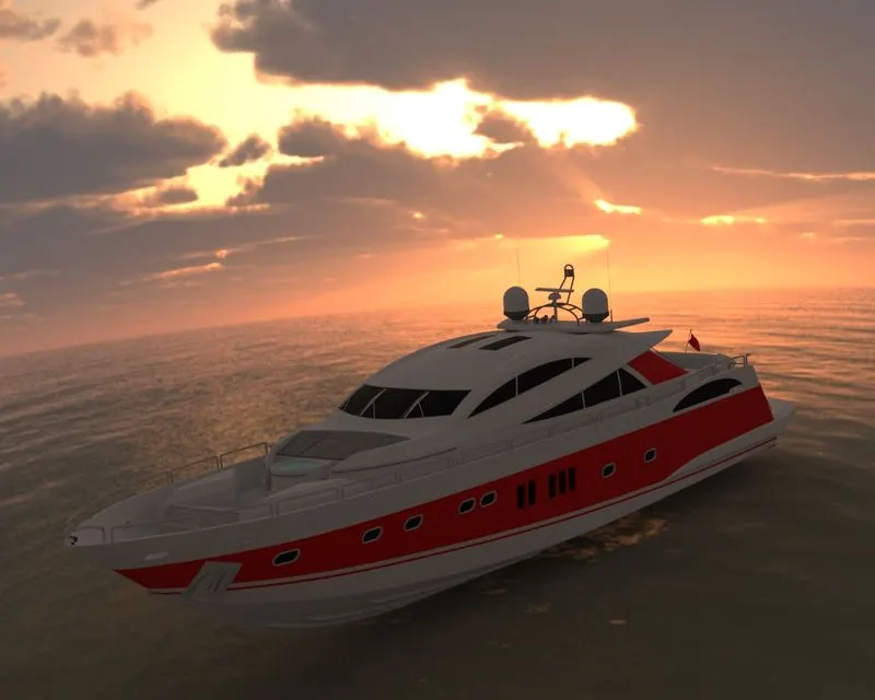
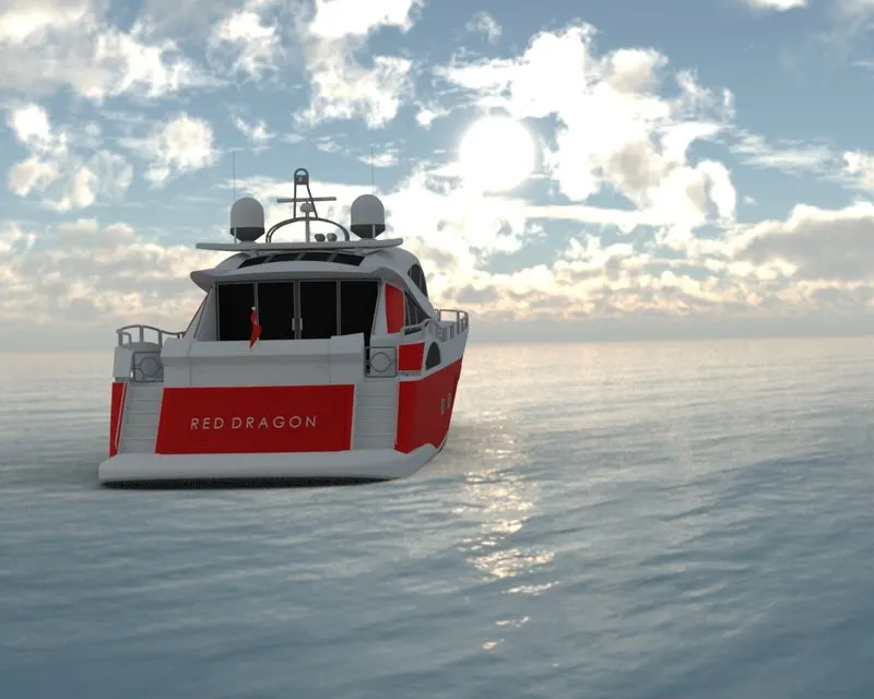
RENDERED IMAGES-ASSEMBLY MODEL
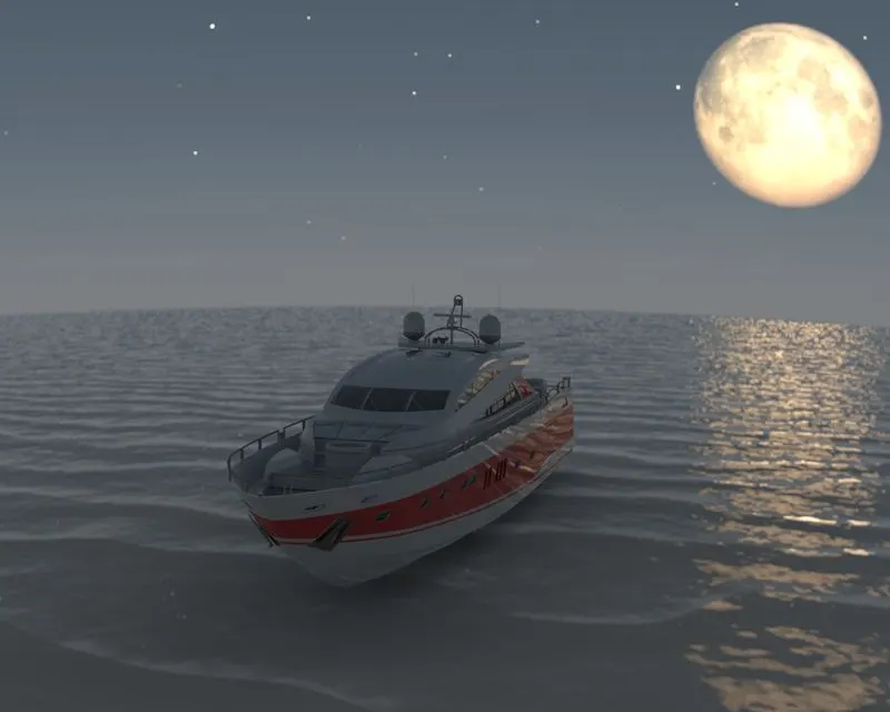
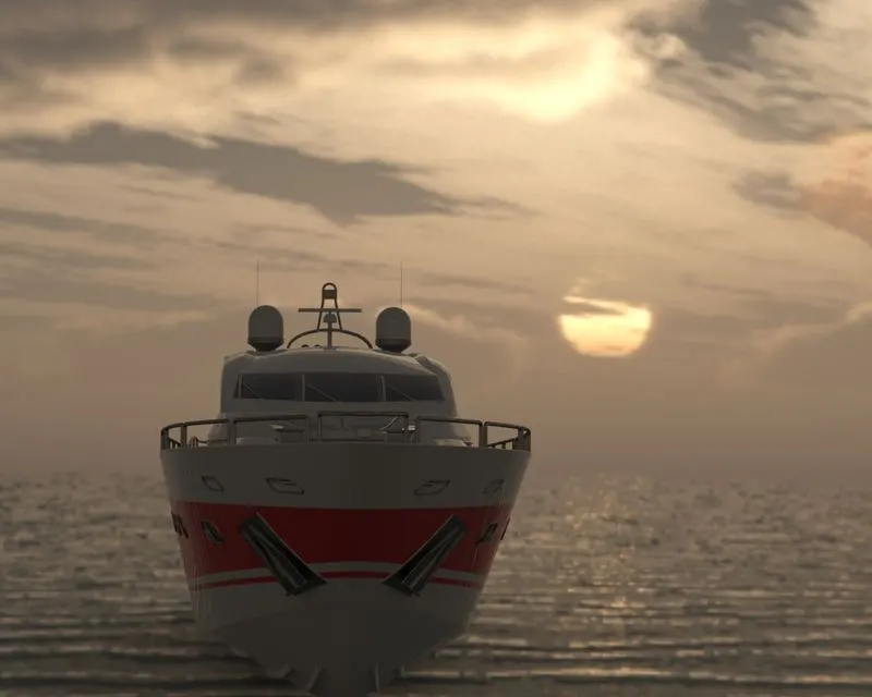
FINAL RENDER- SUNSEEKER PREDATOR YACHT:
CONCLUSION
The practical training on the entire exercise explained above could facilitate us to understand the basic
concepts of surface modelling and assembly modelling using a surface as a reference to design the
Sunseeker Predator Yacht in SolidWorks. We used SolidWorks Visualize to generate the final renders of this
Sunseeker Predator Yacht. Some tweaks with the object orientation, HDR environment, backplate
adjustments, brightness and gamma level, shadows, reflections, scale, adding realistic appearances for
different parts of the Yacht and the result was crisp and realistic images for the final renders.