PWM Controlled Fan Load using DC motor
Aim: To model a fan type load in Simulink and to control its speed by using the PWM method.
Theory
This paper presents the work for the design of the fan speed control system using Pulse Width Modulation by establishing a connection between an H bridge circuit and a Dc motor. A fan type load equation has been used to analyze the output results instead of a physical model of a fan in Simulink. The speed of the fan is varied according to the input voltage using PWM technique.
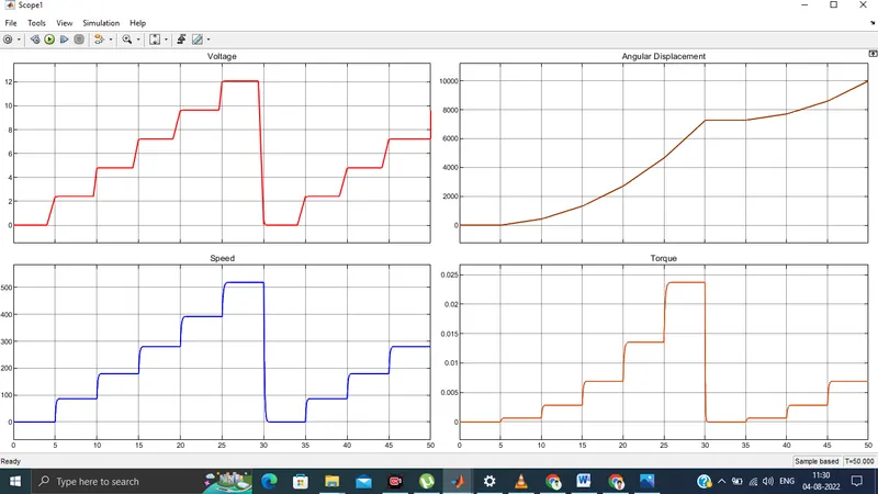
By changing or modulating the timing of these pulses the speed of the motor can be controlled. A stepwise change in the speed variation is given and the full load speed is observed. In this model, all input ports of the H-Bridge block except the PWM port are connected to ground. As a result, the H-Bridge block behaves as follows:
- When the motor is on, the H-Bridge block connects the motor terminals to the power supply.
- When the motor is off, the H-Bridge block acts as a freewheeling diode to maintain the motor current.
Pulse Width Modulation
Pulse width modulation (PWM) is a modulation technique that generates variable-width pulses to represent the amplitude of an analog input signal. The output switching transistor is on more of the time for a high-amplitude signal and off more of the time for a low-amplitude signal.
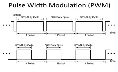
Figure 1:PWM modulation
H-Bridge
An H bridge circuit is a simple circuit that helps in control of a DC motor in forward or backward direction. It containing four switching element (BJT) with load at the center and its configuration is like H type.
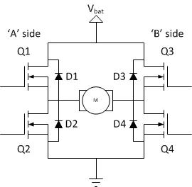
It works like from high voltage/power to ground via following some rules like it can be on when the path of circuit is like (D1 - D4) , simultaneously (D2 - D3) .If it follow the path like (D1 - D2) then it behaves like a low resistance path else like short circuit.Here basically two switches are getting on at same time to complete the circuit from positive to ground.When current starts flowing in the circuit it passes through the motor by which it get energized and starts spinning and it be will ON by switching element (D1 - D4) ON and if we ON the switch(D2 - D3) this will get a negative power by which motor will start rotating in opposite direction.
Load Characteristics
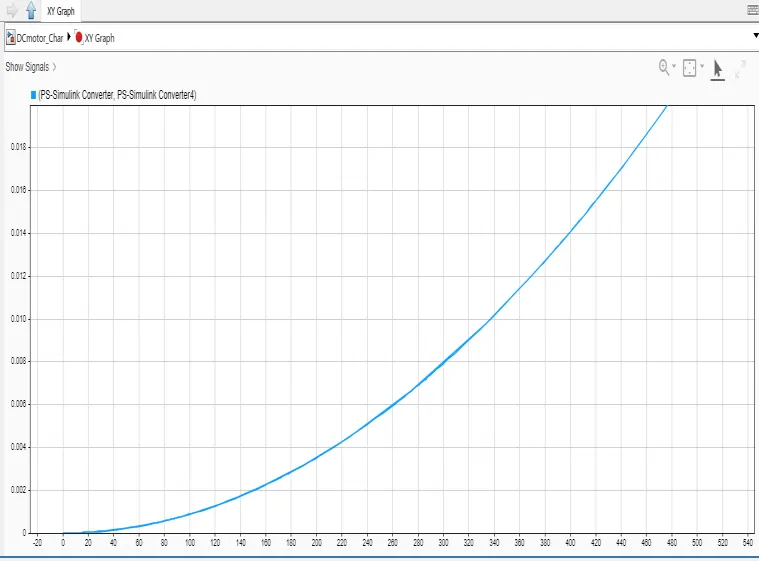
The torque speed curve of a load is a plot showing its torque requirement on the y-axis vs the speed on x axis. It’s the torque requirement of the load from zero speed to full speed. It is load specific and varies with different load types.
The torque at the load will be proportional to the square of the speed.
Model Diagram in Simulink
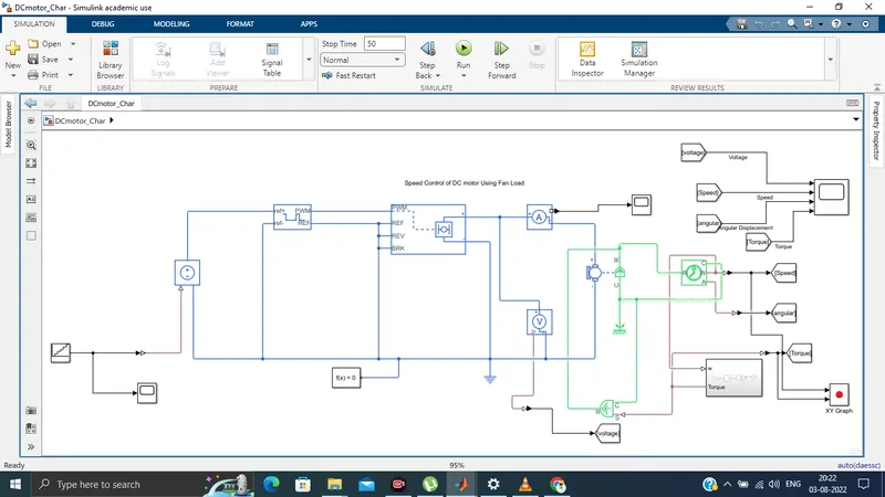
Model description
The DC Motor block uses manufacturer datasheet parameters, which specify the motor as delivering 10W mechanical power at 2500 rpm and no-load speed as 4000 rpm when run from a 12V DC supply. H-bridge block represents a motor drive. The block can be driven by the Controlled PWM Voltage block in Averaged mode.
Results