project 1
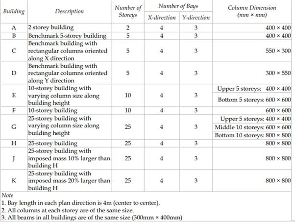
Buildings considered to illustrate concept of natural period: Details of 10 buildings considered
1. CREATION OF THE MODELS
Building A
I. Open eatbs
II. And click on new
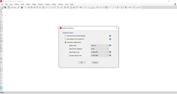
III. In popup set user built in and metric and set the Indian codes
IV.
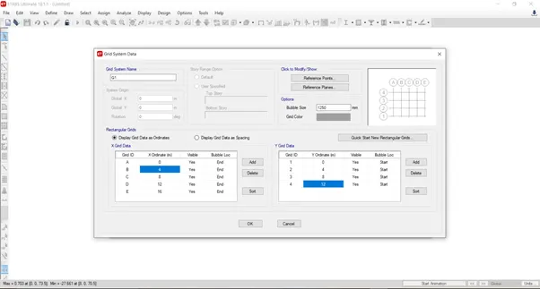
V. Setup the bays
VI.
VII.
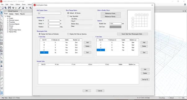
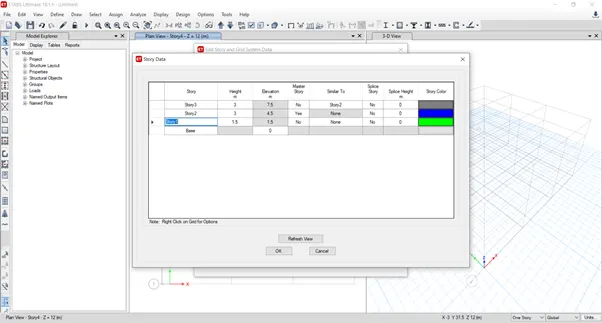
VIII. And then add the stories (2 stories)
IX.
X. Next define material in the define tab
XI.
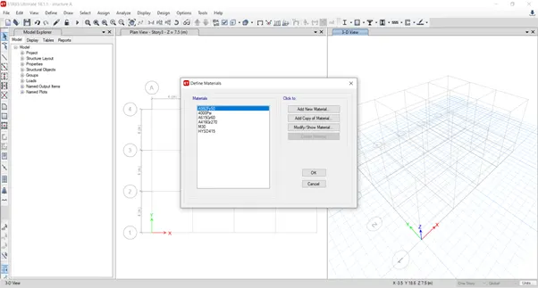
XII.
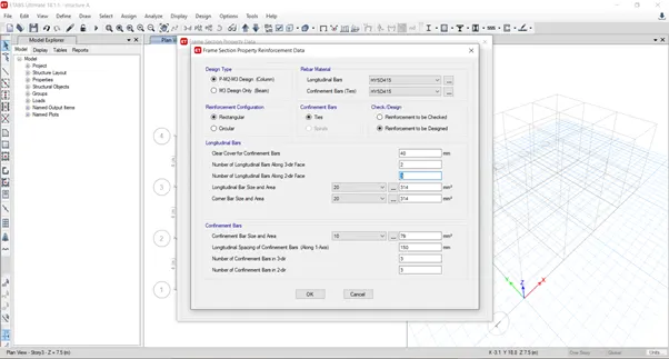
XIII.
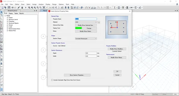
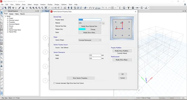
XIV. Both desired columns and beams are defined
XV.
XVI.
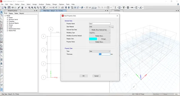
XVII. Slab property is also defined as above
XVIII. Draw/assign the columns by quick draw columns for all stories (column size=400*400mm)
XIX.
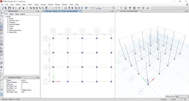
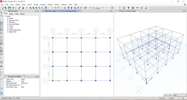
XX. Draw/assign the beams and slabs by quick draw columns for similar stories
XXI.
XXII.
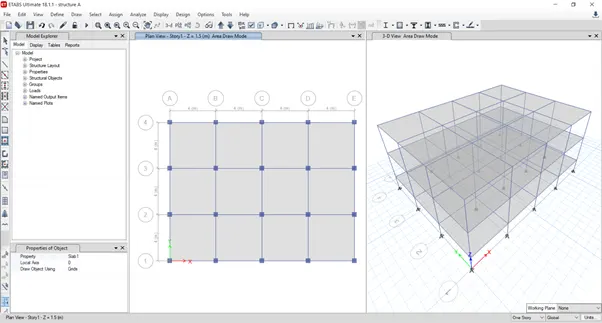
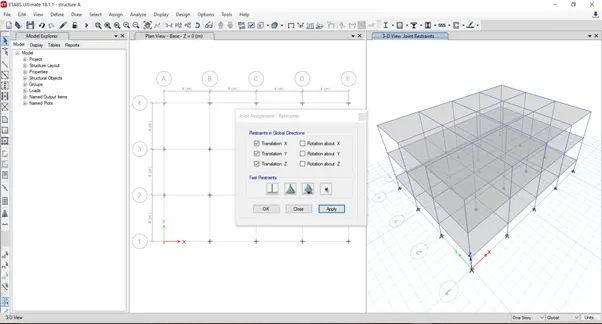
XXIII. Go to base stores select all the joints and assign the base constraints as the point supports
XXIV.
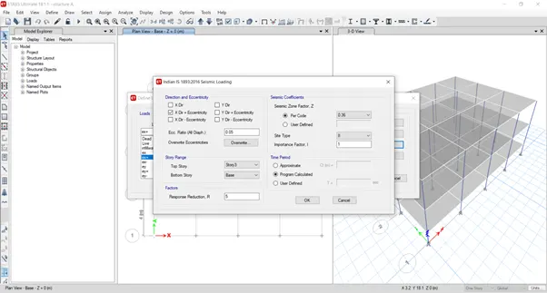
XXV. Define the load patterns
XXVI. Add infill load as super dead and ex,ex+,ex-,ey,ey+,ey- as the seismic loads
XXVII. And modify the lateral loads respectively
XXVIII.
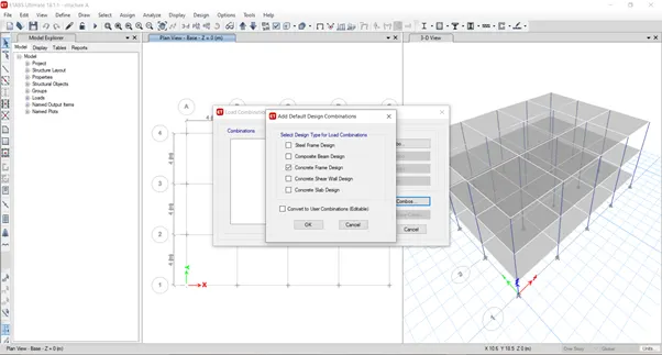
XXIX. Define load combination for the concrete frame automatically
XXX.
XXXI. Assign the infill load of 10kn/m2 on all the beams
XXXII.
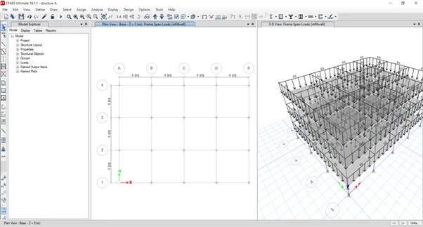
XXXIII. Check the model
XXXIV.
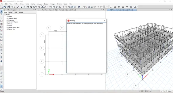
XXXV. Run analysis
XXXVI.
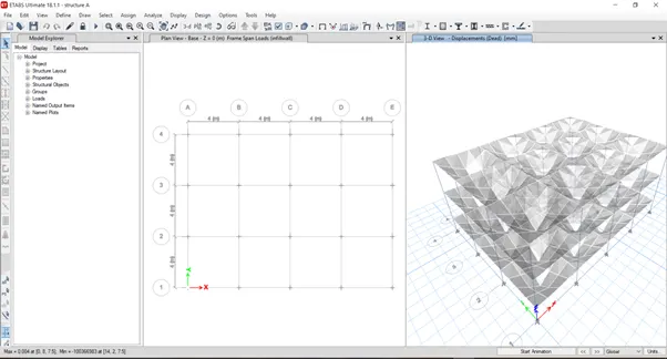
XXXVII. Click on the show tables for the time period of the structure
XXXVIII.
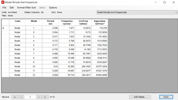
Result:
Time periods are obtained for the building A
Building B
I. Open eatbs
II. And click on new
III. In popup set user built in and metric and set the Indian codes
IV.
V. Setup the bays
VI.
VII. And then add the stories (5 stories)
VIII.
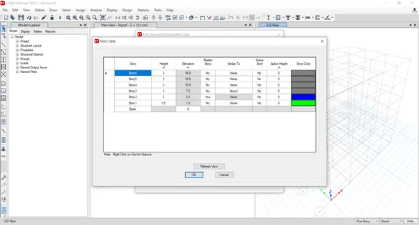
IX. Next define material in the define tab
X. Both desired columns and beams are defined
XI. Slab property is also defined as above
XII. Draw/assign the columns by quick draw columns for all stories (column size=400*400mm)
XIII. Draw/assign the beams and slabs by quick draw columns for similar stories
XIV. Go to base stores select all the joints and assign the base constraints as the point supports
XV. Define the load patterns
XVI. Add infill load as super dead and ex,ex+,ex-,ey,ey+,ey- as the seismic loads
XVII. And modify the lateral loads respectively
XVIII. Define load combination for the concrete frame automatically
XIX. XXXI. Assign the infill load of 10kn/m2 on all the beams
XX.
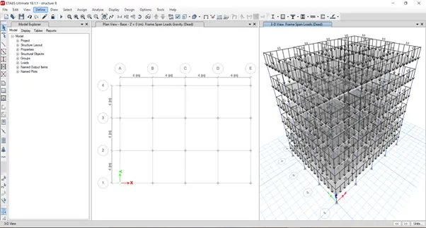
XXI. Check the model
XXII. Run analysis
XXIII.
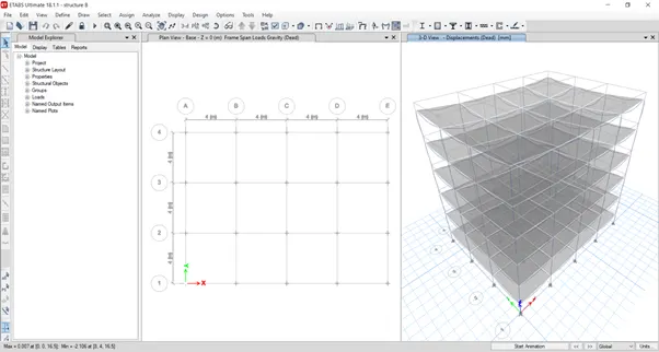
XXIV. Click on the show tables for the time period of the structure
XXV.
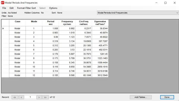
Result:
Time periods are obtained for the building B
Building C
I. In etabs open the building b model and click on save as option and save it as the building c
II. Now go to define section properties
III. Select the column and click on modify
IV. And change the column dimension to the 550 depth *300 width
V.
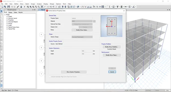
VI. Ok
VII.
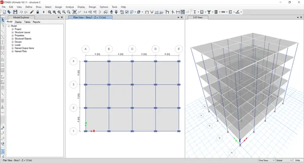
VIII.
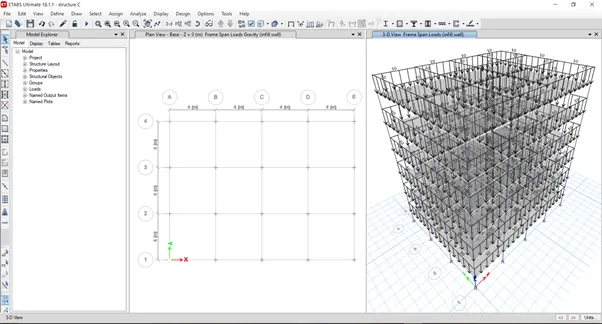
IX. Check model and run analysis
X.
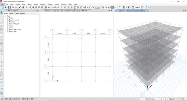
XI. Show tables
XII.
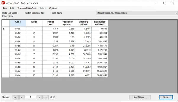
Result:
Time periods are obtained for the building C
Building D
I. In etabs open the building C model and click on save as option and save it as the building D
II. Now go to define section properties
III. Select the column and click on modify
IV. And change the column dimension to the 300 depth * 550 width
V.
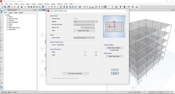
VI. Ok
VII.
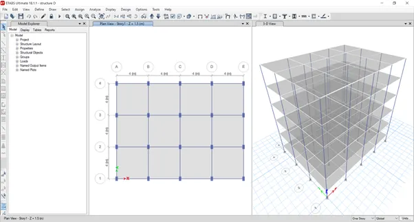
VIII.
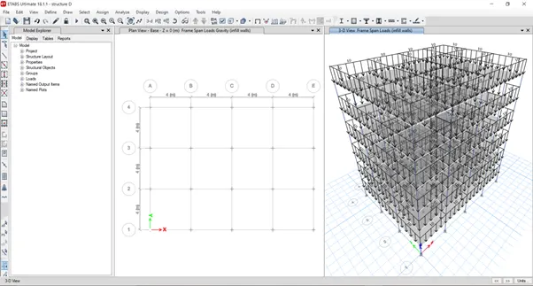
IX. Check model and run analysis
X.
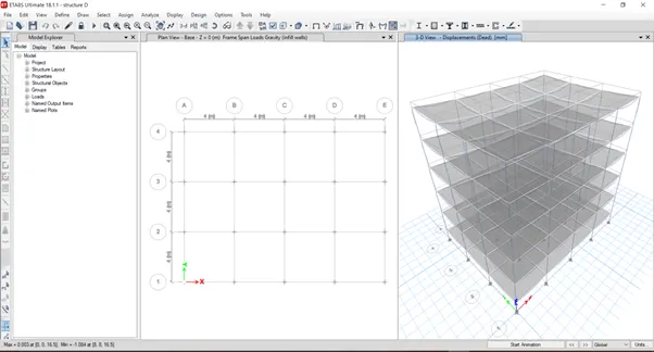
XI. Show tables
XII.
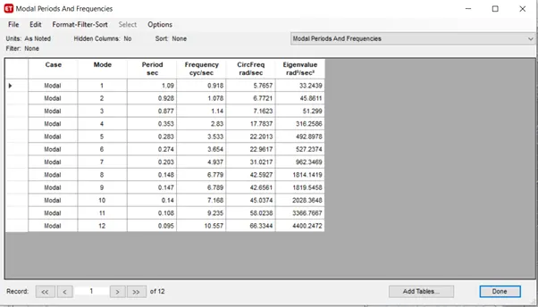
Result:
Time periods are obtained for the building D
Building E
I. Open eatbs
II. And click on new
III. In popup set user built in and metric and set the Indian codes
IV.
V. Setup the bays
VI.
VII. And then add the stories ( stories)
VIII.
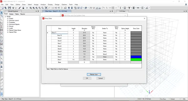
IX. Next define material in the define tab
X. Both desired columns and beams are defined
XI. Slab property is also defined as above
XII. Draw/assign the columns by quick draw columns for all upper 5 stories (column size=400*400mm)
XIII.
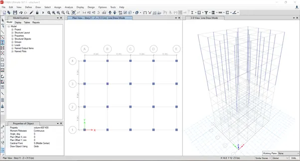
XIV. Draw/assign the columns by quick draw columns for all lower 5 stories (column size=600*600mm)
XV.
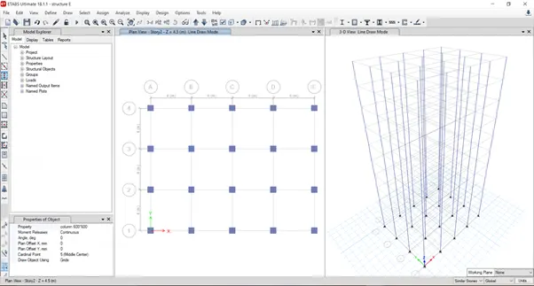
XVI. Draw/assign the beams and slabs by quick draw columns for similar stories
XVII.
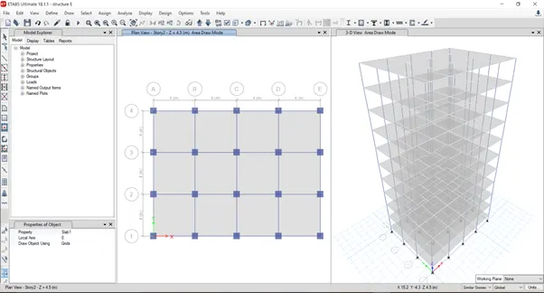
XVIII. Go to base stores select all the joints and assign the base constraints as the point supports
XIX. Define the load patterns
XX. Add infill load as super dead and ex,ex+,ex-,ey,ey+,ey- as the seismic loads
XXI. And modify the lateral loads respectively
XXII. Define load combination for the concrete frame automatically
XXIII. Assign the infill load of 10kn/m2 on all the beams
XXIV.
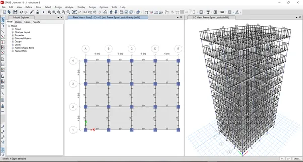
XXV. Check the model
XXVI. Run analysis
XXVII.
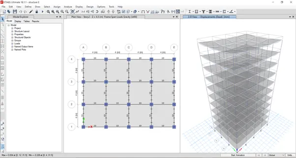
XXVIII. Click on the show tables for the time period of the structure
XXIX.
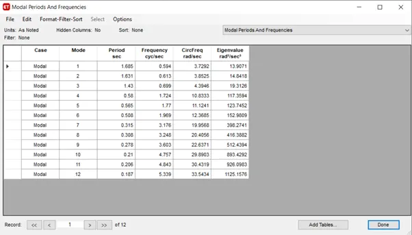
Result:
Time periods are obtained for the building E
Building F
I. In etabs open the building E model and click on save as option and save it as the building F
II. Now go to define section properties
III. Select the column and click on modify
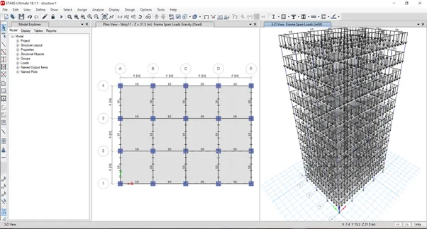
IV. And change the column dimension to the 600 depth * 600 width
I. And assign to the all stories
II.
V. Ok
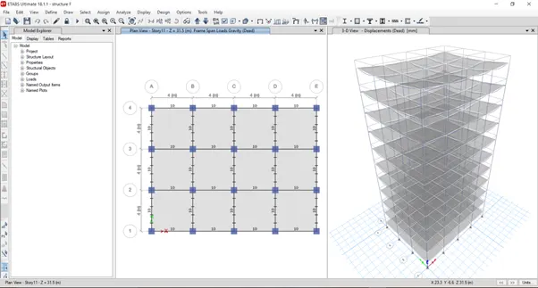
III. Check model and run analysis
IV.
V. Show tables
VI.
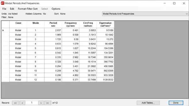
Result:
Time periods are obtained for the building F
Building G
I. Open eatbs
II. And click on new
III. In popup set user built in and metric and set the Indian codes
IV.
V. Setup the bays
VI.
VII. And then add the stories ( 25 stories)
VIII.
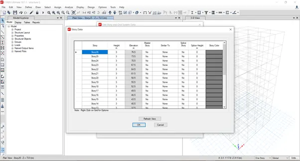
IX. Next define material in the define tab
X. Both desired columns and beams are defined
XI. Slab property is also defined as above
XII. Draw/assign the columns by quick draw columns for all upper 5 stories (column size=400*400mm)
XIII.
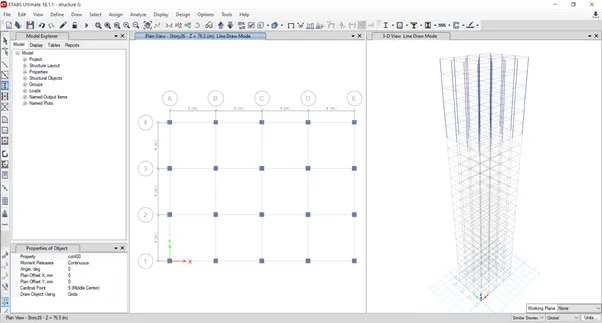
XIV. Draw/assign the columns by quick draw columns for all lower 10 stories (column size=600*600mm)
XV.
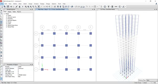
XVI. Draw/assign the columns by quick draw columns for all middle 10 stories (column size=600*600mm)
XVII.
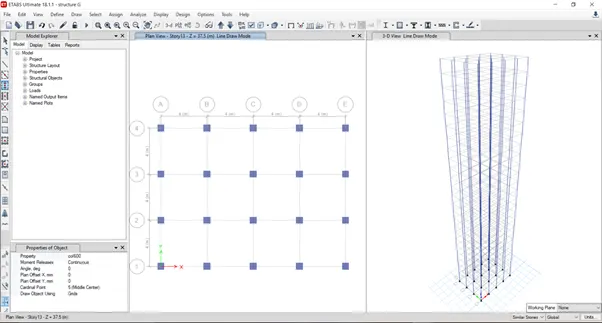
XVIII. Draw/assign the beams and slabs by quick draw columns for similar stories
XIX. Go to base stores select all the joints and assign the base constraints as the point supports
XX. Define the load patterns
XXI. Add infill load as super dead and ex,ex+,ex-,ey,ey+,ey- as the seismic loads
XXII. And modify the lateral loads respectively
XXIII. Define load combination for the concrete frame automatically
XXIV. Assign the infill load of 10kn/m2 on all the beams
XXV.
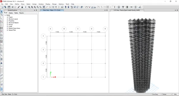
XXVI. Check the model
XXVII. Run analysis
XXVIII.
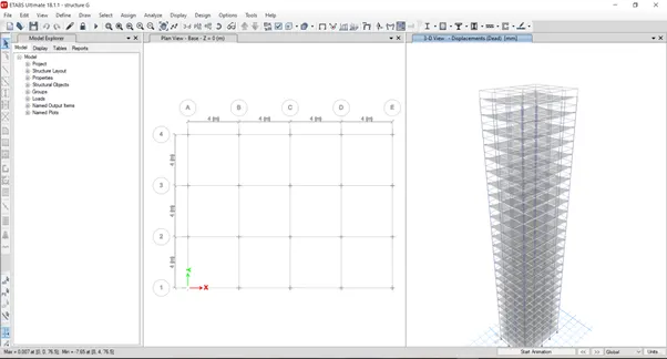
XXIX. Click on the show tables for the time period of the structure
XXX.
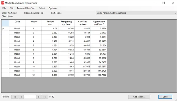
Result:
Time periods are obtained for the building G
Building H
I. In etabs open the building G model and click on save as option and save it as the building H
II. Now go to define section properties
III. Select the column and click on modify
IV. And change the column dimension to the 800 depth * 800 width
V. And assign to the all stories
VI. Now go to define mass source
VII. And modify the infill loads by adding 10%
VIII.
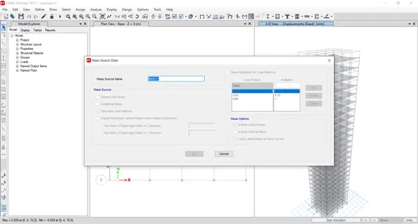
IX. Ok
X.
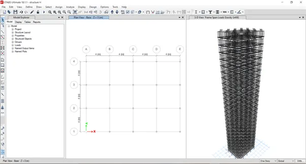
XI. Check model and run analysis
XII.
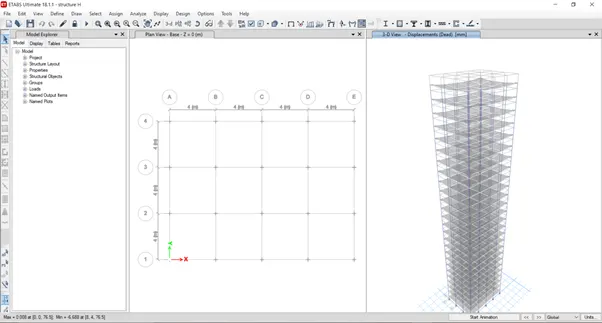
XIII. Show tables
XIV.
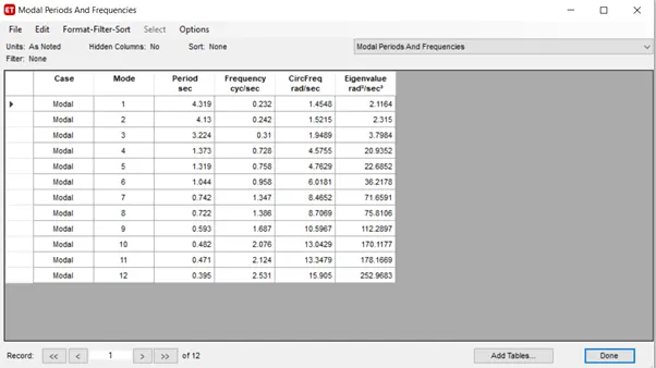
Result:
Time periods are obtained for the building H
Building J
I. In etabs open the building H model and click on save as option and save it as the building J
II. Now go to define mass source
III. And modify the infill loads by adding 10%
IV.
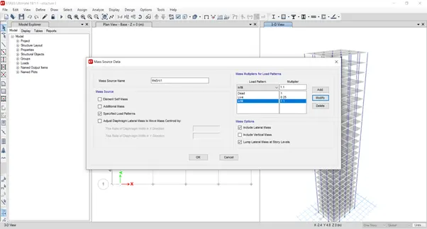
V. Ok
VI.
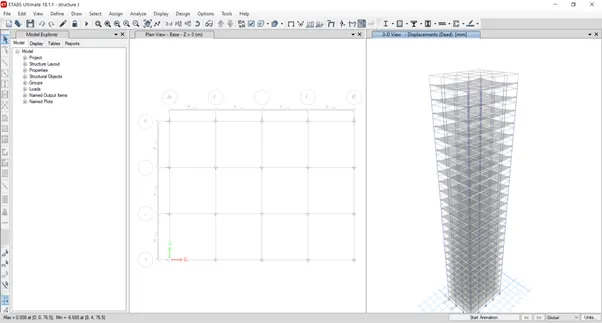
VII. Check model and run analysis
VIII. Show tables
IX.
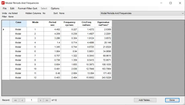
Result:
Time periods are obtained for the building J
Building K
I. In etabs open the building H model and click on save as option and save it as the building J
II. Now go to define mass source
III. And modify the infill loads by adding 10%
IV.
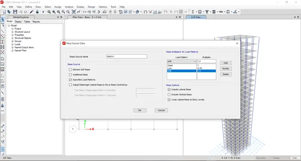
V. Ok
VI. Check model and run analysis
VII.
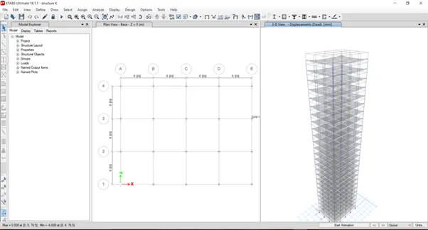
VIII. Show tables
IX.
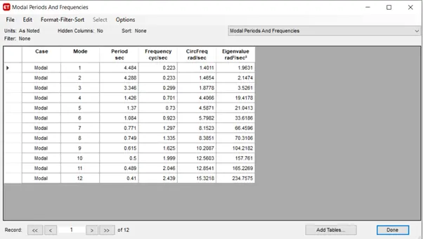
Result:
Time periods are obtained for the building K
2.COMPARISION OF THE MODELS
Effect of stiffness on T: Compare fundamental natural periods of buildings E & F as well as G & H. Why is there a marginal or significant difference in the fundamental natural periods?
E
F
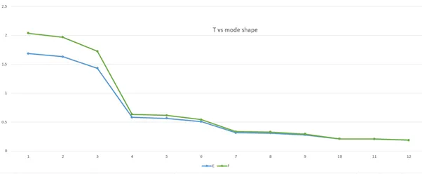
The fundamental natural period of the buildings E and F are compared in the above graph where the building F has the higher natural period compared to the building E because the building F is flexible with the usage of the same column throughout the height of the building and also the size of the column is bigger compared to the building E for half of the floors.
Even though there is the variation in the natural period it is very little because the dimensions of only half of the building’s columns are different and their size difference is also less.
G
H
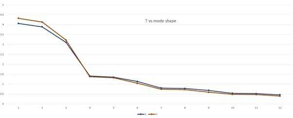
Similar to the building E and F, The fundamental natural period of the buildings G and H are compared in the above graph where the building H has the higher natural period compared to the building G because the building H is flexible with the usage of the same column throughout the height of the building and also the size of the column is bigger compared to the building G for half of the floors.
Even though there is the variation in the natural period it is very little because the dimensions of only half of the building’s columns are different and their size difference is also less.
Effect of mass on T: Compare fundamental natural periods of buildings H, J and K. Have the buildings become more flexible or stiff due to change in mass?
H
J
K
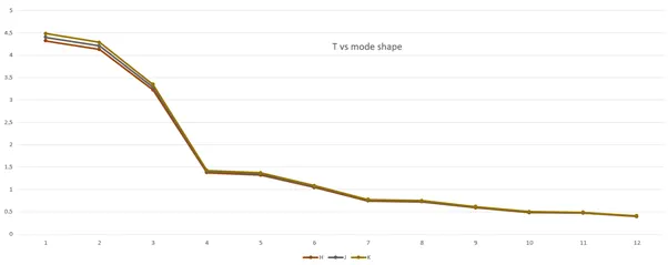
In the above graph there is the comparison of the natural period of the buildings H, K and J where the imposed mass of the buildings are increased respectively by the 10% and all other parameters are same for the building
As shown in the graph building K has the higher natural period and then followed by the building J and H. by this we can say the more the mass acting on the building more will be the natural period of the building.
Effect of Building Height on T: How does the fundamental natural periods of Buildings A, B, F and H change with change in building height?
A
B
F
H
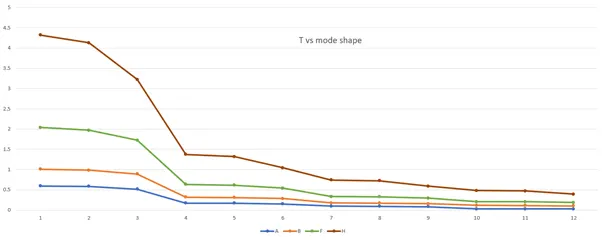
In the above graph there is the comparison of the natural period of the buildings A, B, F and H where the height of the building and increased respectively in the order
By seeing the graph, we can conclude that the higher the height of the building more in the natural period of the building. Therefore, height of the structure is directly proportional to the natural period of the building.
Effect of Column Orientation on T: How does the fundamental natural periods of Buildings B, C and D change with change in column orientation?
B
C
D
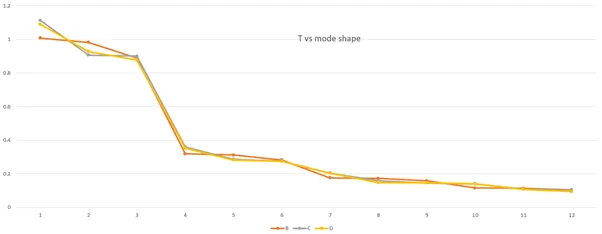
In the above graph there is the comparison of the natural period of the buildings B, C and D where the column orientation of the building C and D are changed in the X and Y directions by 90 deg. And type of the column in building B is symmetric in both directions and building C and D has unsymmetrical columns with long and the short face. 3 building has the columns of the same cross-sectional area.
In the graph we can see that the building with the unsymmetric columns (C and D) have the similar natural periods. This says orientation has the less impact on the natural period.
But when comparing the symmetric (B) and unsymmetric building (C and D) symmetric building will posses the less natural period at the initial mode shapes.
Comparison of all the buildings
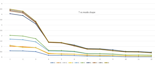
In the graph above natural periods of the all the buildings were provided for the 12 mode shapes.