Projefct 1_Comparative study of different storey buildings for Seismic forces
Ans:
Aim:- Comparative study of buildings
Frame section properties:
Beam -300 mm*400 mm
Beam -400 mm*400 mm
Beam -600 mm*600 mm
Beam -800 mm*800 mm
Beam -330 mm*500 mm
Beam -500 mm*330 mm
Shell Section property
Slab -150 mm thick
Load:
Live load-3kN/m^2
Infill wall load-10kN/m^2
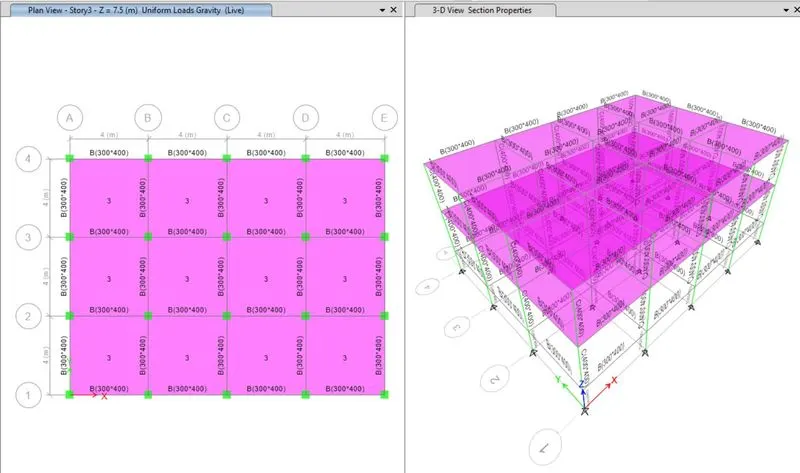
Modelling of Building A:-
- Open the New model
- Setting Building A as 2 storeys and number of bays in X direction as 4 and Number of bays in Y direction as 3.
- Defining the Material properties as M 30 concrete and Fe 415 steel.
- Define the frame section Properties and Shell section properties.
- Using the quick draw command draw the columns Beams and Slabs.
- Define the load patterns that is infill wall loads and live loads.
- Select the Beams of all the floors and assign infill wall load as 10 kN/m^2.
- Select the floors of all the slabs and assign the live load 3kN/m^2.
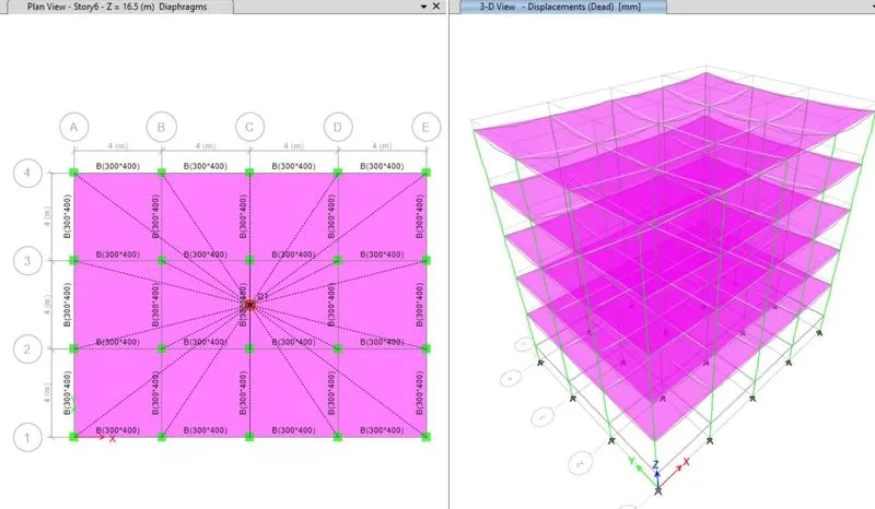
- Assign the diaphragms
- Save the model and run the analysis.
- Go to display tab and select the show table option.
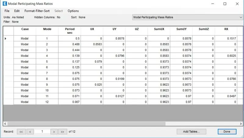
- Checking the modal participating ratio.
Modelling of Building B:-
- Open the New model
- Setting Building A as 5 storeys and number of bays in X direction as 4 and Number of bays in Y direction as 3.
- Defining the Material properties as M 30 concrete and Fe 415 steel.
- Define the frame section Properties and Shell section properties.
- Using the quick draw command draw the columns Beams and Slabs.
- Define the load patterns that is infill wall loads and live loads.
- Select the Beams of all the floors and assign infill wall load as 10 kN/m^2.
- Select the floors of all the slabs and assign the live load 3kN/m^2.
- Assign the diaphragms
- Save the model and run the analysis.
- Go to display tab and select the show table option.
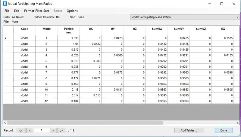
- Checking the modal participating ratio.
-
Modelling of Building C:-
- Open the New model
- Setting Building A as 5 storeys and number of bays in X direction as 4 and Number of bays in Y direction as 3.
- Defining the Material properties as M 30 concrete and Fe 415 steel.
- Define the frame section Properties and Shell section properties.
- Columns are oriented in the X direction
- Using the quick draw command draw the columns Beams and Slabs.
- Define the load patterns that is infill wall loads and live loads.
- Select the Beams of all the floors and assign infill wall load as 10 kN/m^2.
- Select the floors of all the slabs and assign the live load 3kN/m^2.
- Assign the diaphragms
- Save the model and run the analysis.
- Go to display tab and select the show table option.
- Checking the modal participating ratio.
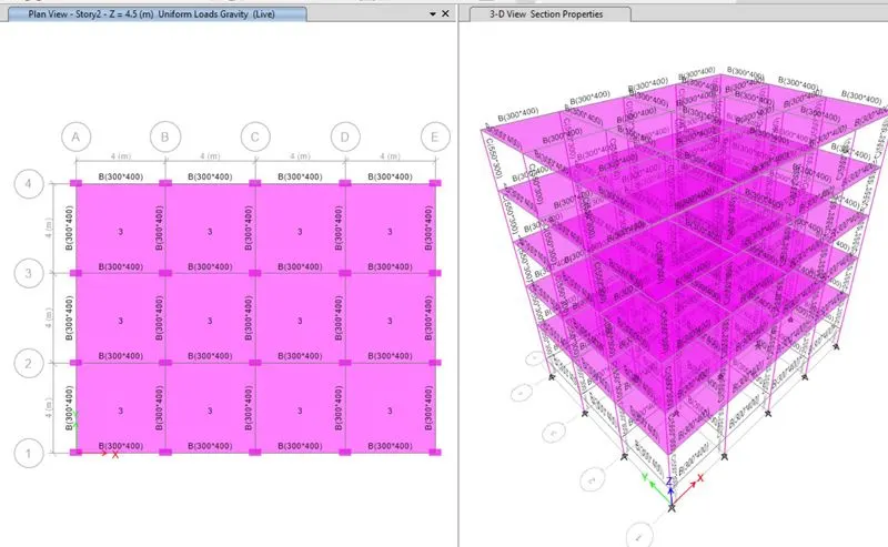
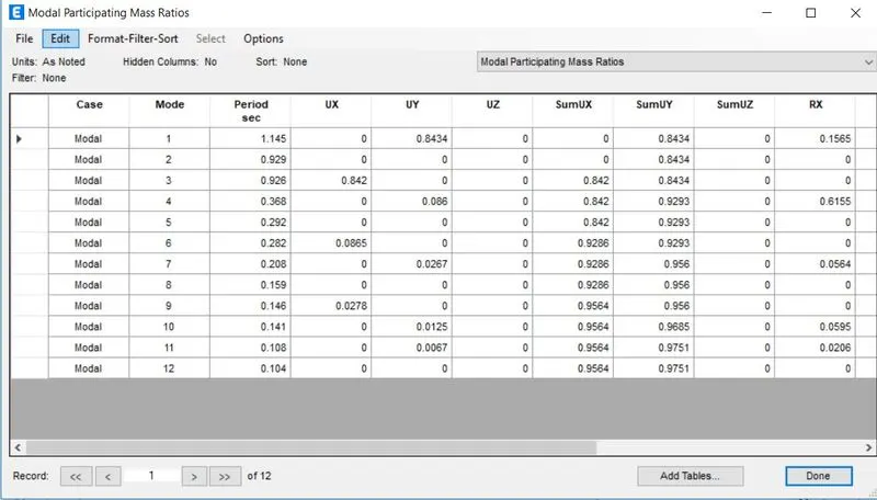
-
Modelling of Building D:-
- Open the New model
- Setting Building A as 5 storeys and number of bays in X direction as 4 and Number of bays in Y direction as 3.
- Defining the Material properties as M 30 concrete and Fe 415 steel.
- Define the frame section Properties and Shell section properties.
- Columns are oriented in the Y direction
- Using the quick draw command draw the columns Beams and Slabs.
- Define the load patterns that is infill wall loads and live loads.
- Select the Beams of all the floors and assign infill wall load as 10 kN/m^2.
- Select the floors of all the slabs and assign the live load 3kN/m^2.
- Assign the diaphragms
- Save the model and run the analysis.
- Go to display tab and select the show table option.
- Checking the modal participating ratio.
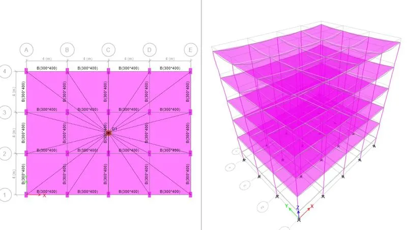
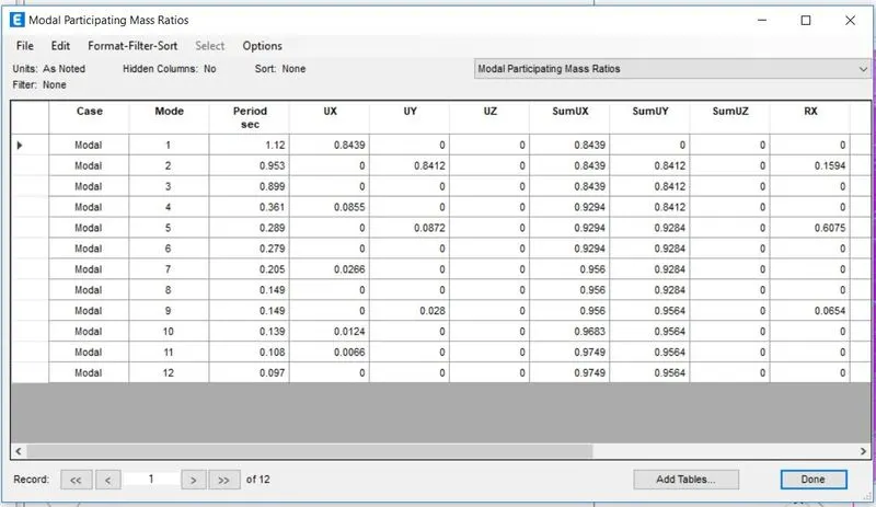
Modelling of Building E:-
- Open the New model
- Setting Building A as 10 storeys and number of bays in X direction as 4 and Number of bays in Y direction as 3.
- Defining the Material properties as M 30 concrete and Fe 415 steel.
- Define the frame section Properties and Shell section properties.
- Columns Dimensions are different in upper , middle and lower storeys
- Using the quick draw command draw the columns Beams and Slabs.
- Define the load patterns that is infill wall loads and live loads.
- Select the Beams of all the floors and assign infill wall load as 10 kN/m^2.
- Select the floors of all the slabs and assign the live load 3kN/m^2.
- Assign the diaphragms
- Save the model and run the analysis.
- Go to display tab and select the show table option.
- Checking the modal participating ratio.
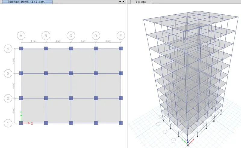
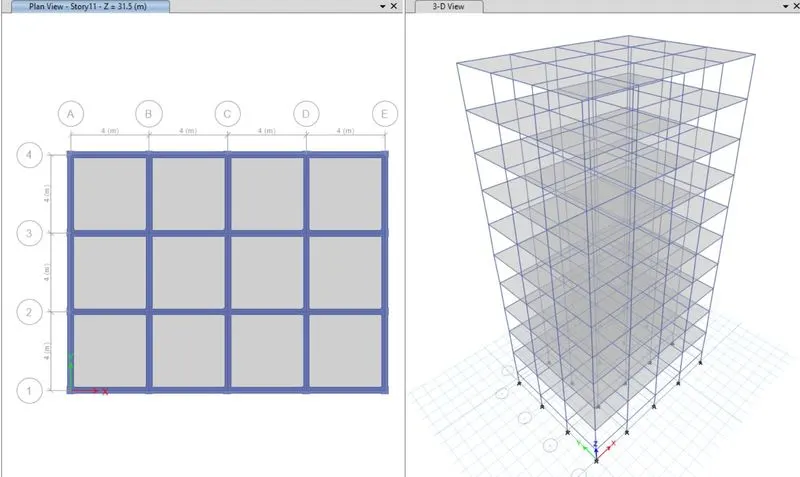
Modelling of Building F:-
- Open the New model
- Setting Building A as 10 storeys and number of bays in X direction as 4 and Number of bays in Y direction as 3.
- Defining the Material properties as M 30 concrete and Fe 415 steel.
- Define the frame section Properties and Shell section properties.
- Columns Dimensions are same that is 600*600.
- Using the quick draw command draw the columns Beams and Slabs.
- Define the load patterns that is infill wall loads and live loads.
- Select the Beams of all the floors and assign infill wall load as 10 kN/m^2.
- Select the floors of all the slabs and assign the live load 3kN/m^2.
- Assign the diaphragms
- Save the model and run the analysis.
- Go to display tab and select the show table option.
- Checking the modal participating ratio.

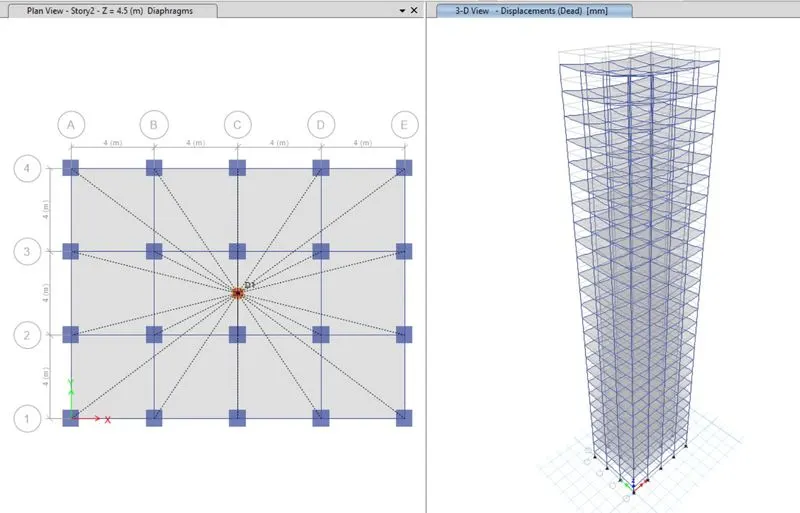
Modelling of Building G:-
- Open the New model
- Setting Building A as 25 storeys and number of bays in X direction as 4 and Number of bays in Y direction as 3.
- Defining the Material properties as M 30 concrete and Fe 415 steel.
- Define the frame section Properties and Shell section properties.
- Columns Dimensions are different in upper , middle and lower stories
- Using the quick draw command draw the columns Beams and Slabs.
- Define the load patterns that is infill wall loads and live loads.
- Select the Beams of all the floors and assign infill wall load as 10 kN/m^2.
- Select the floors of all the slabs and assign the live load 3kN/m^2.
- Assign the diaphragms
- Save the model and run the analysis.
- Go to display tab and select the show table option.
- Checking the modal participating ratio.
Modelling of Building H:-
- Open the New model
- Setting Building A as 25 storeys and number of bays in X direction as 4 and Number of bays in Y direction as 3.
- Defining the Material properties as M 30 concrete and Fe 415 steel.
- Define the frame section Properties and Shell section properties.
- Columns Dimensions are same in all the storeys i.e 800*800.
- Using the quick draw command draw the columns Beams and Slabs.
- Define the load patterns that is infill wall loads and live loads.
- Select the Beams of all the floors and assign infill wall load as 10kN/m^2.
- Select the floors of all the slabs and assign the live load 3kN/m^2.
- Assign the diaphragms
- Save the model and run the analysis.
- Go to display tab and select the show table option.
- Checking the modal participating ratio.
Modelling of Building J:-
- Open the New model
- Setting Building A as 25 storeys and number of bays in X direction as 4 and Number of bays in Y direction as 3.
- Defining the Material properties as M 30 concrete and Fe 415 steel.
- Define the frame section Properties and Shell section properties.
- Columns Dimensions are same in all the storeys i.e 800*800.
- Using the quick draw command draw the columns Beams and Slabs.
- Define the load patterns that is infill wall loads and live loads.
- Select the Beams of all the floors and assign infill wall load as 11kN/m^2.
- Select the floors of all the slabs and assign the live load 3.3kN/m^2.
- Assign the diaphragms
- Save the model and run the analysis.
- Go to display tab and select the show table option.
- Checking the modal participating ratio.
Modelling of Building K:-
- Open the New model
- Setting Building A as 25 storeys and number of bays in X direction as 4 and Number of bays in Y direction as 3.
- Defining the Material properties as M 30 concrete and Fe 415 steel.
- Define the frame section Properties and Shell section properties.
- Columns Dimensions are same in all the storeys i.e 800*800.
- Using the quick draw command draw the columns Beams and Slabs.
- Define the load patterns that is infill wall loads and live loads.
- Select the Beams of all the floors and assign infill wall load as 12kN/m^2.
- Select the floors of all the slabs and assign the live load 3.6kN/m^2.
- Assign the diaphragms
- Save the model and run the analysis.
- Go to display tab and select the show table option.
- Checking the modal participating ratio.
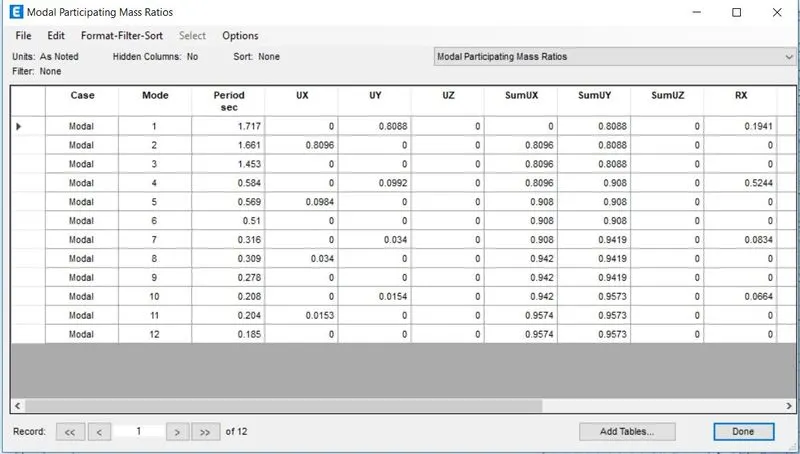
Effect of stiffness on Natural Period (T) on building E and F , as well on G and H.
Time period of Building E-
Tx1-1.717
Ty1-1.661
R1-1.453
Time period of Building F
Tx1-1.735
Ty1-1.678
R1-1.468
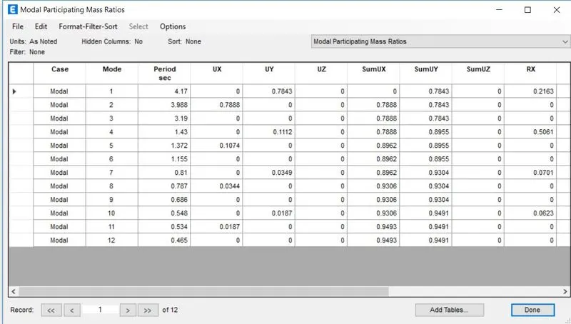
Time period of Building G
Tx1-4.17
Ty1-3.988
R1-3.19
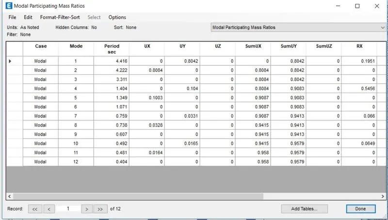
Time period of Building H
Tx1-4.416
Ty1-4.22
R1-3.311
When comparing the above results, The time period for building F and H is increased. We can say that by changing the sectional properties of the buildings the time period also varies. Alsoby referring to the time period formula we can observe that time period Is directly proportional to the mass of the building.
if the mass of the building is increased then the time period also will be increased. Also the stiffness in inversely proportional to time period so there wont be any drastic changes in the time periods .
Effect of mass on Natural periods of buildings H ,J and K.
Time period of Building H
Tx1-4.416
Ty1-4.22
R1-3.311
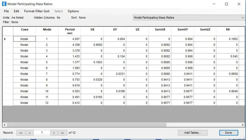
Time period of Building J
Tx1-4.507
Ty1-4.309
R1-3.378
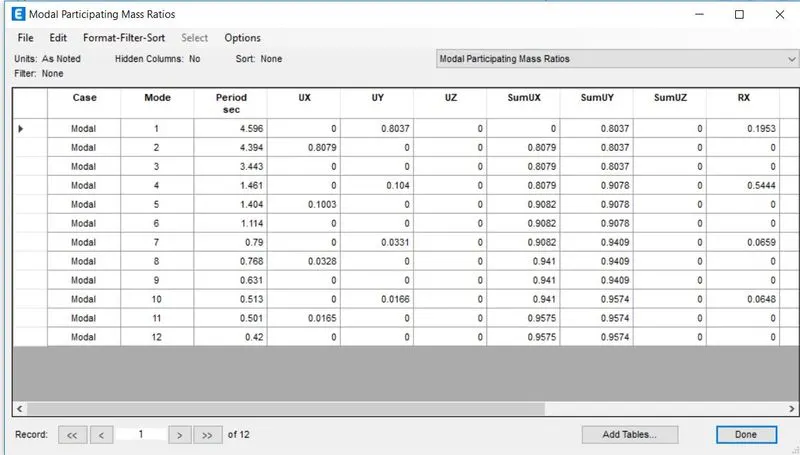
Time period of Building K
Tx1-4.596
Ty1-4.394
R1-3.394
Comparing the building H and J,K , in the building J the imposed loads were increased by 10% than in the Building H. in the building K the imposed loads were increased by 20% than in the Building H.from the time period formula we know that mass is directly proportional to time period hence we can conclude that if the masses of the buildings were increased then the time periods will also be increased.
Also the imposed masses are not the part of the stiffness. imposed masses will be due to the loads coming because of infill walls and also from the live loads on the slabs.
Effect of height on fundamental natural period of A , B ,F,H
Time period of Building A
Tx1-0.5
Ty1-0.488
R1-0.444
Time period of Building B
Tx1-1.036
Ty1-1.01
R1-0.912
Time period of Building F
Tx1-1.735
Ty1-1.678
R1-1.468
Time period of Building H
Tx1-4.416
Ty1-4.42
R1-3.312
If we compare the building -A(2 storey building) and Building B-(Storey -5) the time period of B is higher than that of building A. If we compare the building -F(10 storey building) and Building H-(Storey -25) the time period of H is higher than that of building. we know that stiffness formula
k=3EI/h3
it means height of the building is inversely proportional to stiffness k of the building, and time period of the building is inversely proportional to k.
T
That is T
That is with increase in the height of building the time period of the also increases.
Effect of height on fundamental natural period of Buildings B,C,D with change in the orientation of the columns.
Time period of Building B
Tx1-1.036
Ty1-1.01
R1-0.912
Time period of Building C
Tx1-1.415
Ty1-0.929
R1-0.926
Time period of Building D
Tx1-1.12
Ty1-0.958
R1-0.899
To compare easily the stiffness participation in each direction of the Buildings -B,C and D.
Building B has squire columns.
Building C – The time period in X direction of building C is more than that of time period in X direction of Building B as the the column dimension in X direction is more in case of Building C hence stiffness will be less and time period will be more in building C than in Building D.
The time period in Y direction of building D is more than that of time period in Y direction of Building C as the the column dimension in Y direction is more in case of Building D hence stiffness will be less and time period will be more in building D than in Building C in the Y direction.