Project - Speed Control of a Direct Current (DC) motor
1. Speed Control of a Direct Current (DC) motor:
Mathematical model of DC motor:
w(s)/Vs(s) = Kt/((J*La*s^2)+(J*Ra+B*La)*s+(B*Ra+kt*km))
% design parameters
J = 0.01; %moment of inertia of the rotor in kg-m^2
B = 0.01; % motor viscous friction constant in N-m-s
Km = 0.01; % Back EMF constant in v/rad/s
Kt = 0.01; % Motor torque constant in N-m/amp
Ra = 1.0; % resistance of the armature circuit in ohms
La = 0.05; %Inductance of the armature circuit
Simulink model:
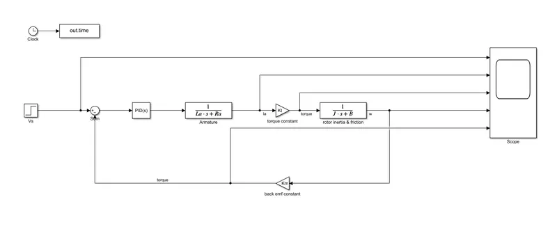
output:
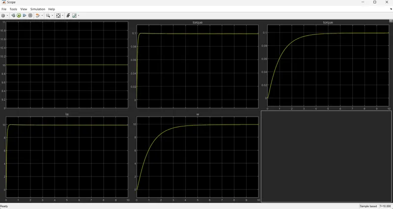
Implementing Proportional, Integral, and Derivative (PID) control:
% design parameters
J = 0.01; %moment of inertia of the rotor in kg-m^2
B = 0.01; % motor viscous friction constant in N-m-s
Km = 0.01; % Back EMF constant in v/rad/s
Kt = 0.01; % Motor torque constant in N-m/amp
Ra = 1.0; % resistance of the armature circuit in ohms
La = 0.05; %Inductance of the armature circuit
% design parameters
wn = 6.2832;
fn = 1.0;
zeta = 0.5;
% desired poles
p1 = -zeta*wn+wn*sqrt(zeta^2-1);
p2 = -zeta*wn-wn*sqrt(zeta^2-1);
P = [p1;p2];
% A & B matrices
A = [-92.1811 -10.5350;57.7878 -0.1333];
B = [8.2305;0];
% pole placement design
K = place(A,B,P);
// using pole placement to determine Kp and Kd.
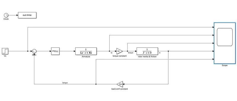
Simulink model:
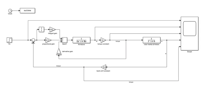
the model contains the calculated gain values form pole placement method.
output:
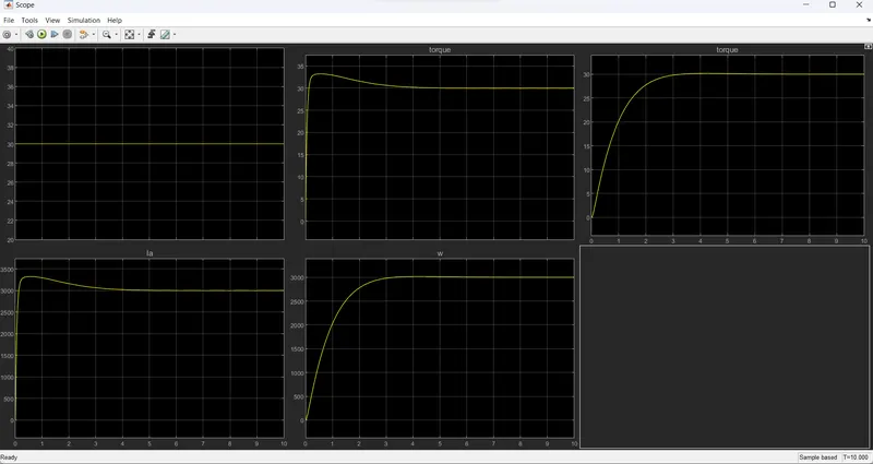
for supply voltage = 10, Ki = 30, Kp = -10.4527, Kd = -1.1987:
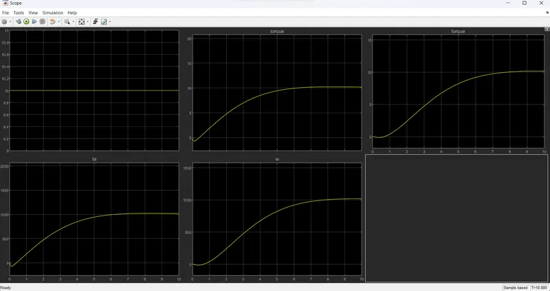
for supply voltage = 10, Ki = 130, Kp = 110, Kd = 7:
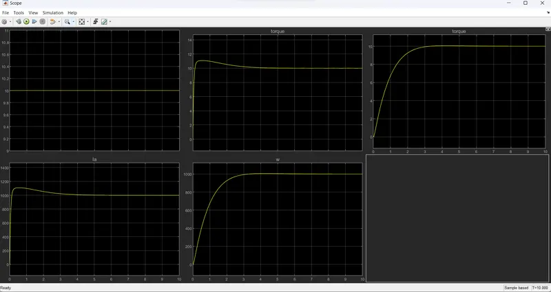
for supply voltage = 30:
the system is replaced by simulink PID block and tested:
output:
for supply voltage = 10, Ki = 130, Kp = 110, Kd = 5:
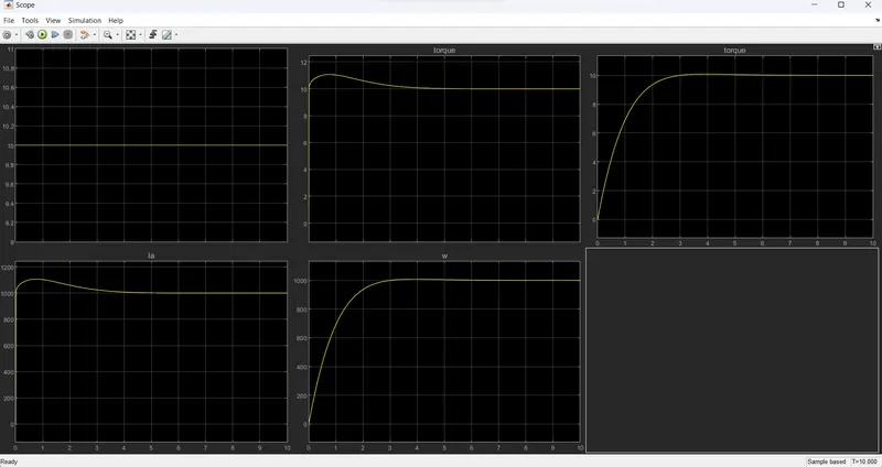
observation:
from this we know that the designed PID controller for DC motor speed control is working properly compared to the simulink built-in PID block.
thus the PID control for DC motor speed control is designed using simulink.