Project - Speed Control of a Direct Current (DC) motor
A PID controller is designed to demonstrate to obtain the desired angular speed using the appropriate supply voltage.
Design parameters to model a DC motor are given below(let's assume):-
J = 0.01 kgm^2 = moment of inertia of the rotor
B = 0.1 Nm = motor viscous friction constant
Km = 0.01 V/rad/s = back emf constant
Kt = 0.01 Nm/Ampere = motor torque constant
Ra = 1ohm = armature resistance
La = 0.5 Henry = armature inductance
Equivalent parameters
fn = 1.0 = natural frequency in Hz
wn = 2*pi*fn = freq. in rad/sec
Design Parameters
For underdamped system i.e.
a) zeta = 0.5
b) zeta = 0.9 nearly to critically damped system i.e 1.0
To find out the desired poles poles for the given design parameters can be calculated as:-
p1 = -zeta*wn+wn*sqrt(zeta^2-1)
p2 = -zeta*wn-wn*sqrt(zeta^2-1)
P = [p1;p2]
A & B matrices are designed below:
considering the state space model,
A = [-B/J Kt/J; -Km/La -Ra/La]
B = [0; 1/La]
Poles placement
K = place(A,B,P)
here K will contain two values K = [K(1) K(2)]
let us take K(1) = Kp and K(2) = Kd, (here Kp and Kd are considered as proportional gain and derivative gain)
But we need to design PID controller for a DC motor, so the integral part comes into the picture.
PID:- The term PID stands for proportional integral derivative and it is one kind of device used to control different process variables like pressure, flow, temperature, and speed in industrial applications. In this controller, a control loop feedback device is used to regulate all the process variables.
PID controller block diagram:
A closed-loop system like a PID controller includes a feedback control system. This system evaluates the feedback variable using a fixed point to generate an error signal. Based on that, it alters the system output. This procedure will continue till the error reaches Zero otherwise the value of the feedback variable becomes equivalent to a fixed point.
This controller provides good results as compared with the ON/OFF type controller. In the ON/OFF type controller, simply two conditions are obtainable to manage the system. Once the process value is lower than the fixed point, then it will turn ON. Similarly, it will turn OFF once the value is higher than a fixed value. The output is not stable in this kind of controller and it will swing frequently in the region of the fixed point. However, this controller is more steady & accurate as compared to the ON/OFF type controller.
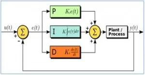
The general equation of a PID controller can be defined as:-
i.e u(t) = Kpe(t)+Ki `int`e(t) dt+Kd d[e(t)]/dt
Considering the dynamics of the equation
x1_dot = x2
x2_dot = (-k/m)x1 + (1/m)*u
x2_dot = (-k/m)x1 + (1/m)*[Kp*(xref-x1) - Kdx2 + Ki*int(xref-x1)*dt
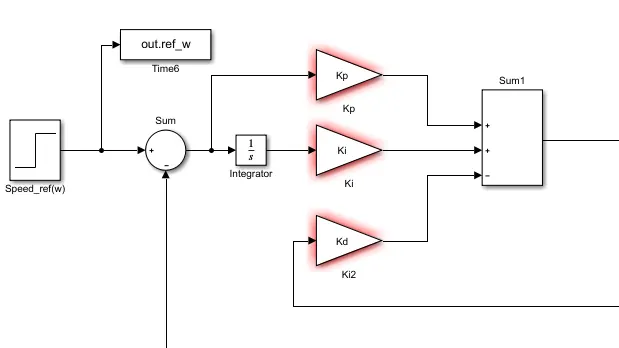
the output of the PID controller serves as an input voltage to armature circuit of a DC motor.
PID controller :-
Mathematical modelling of DC motor:-
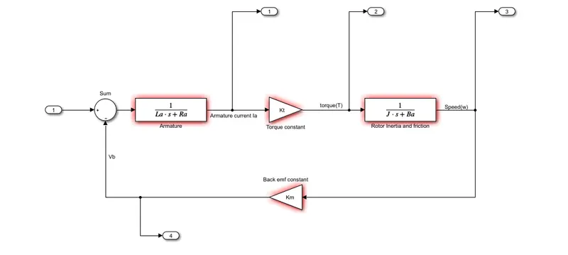
Simulink based modelling:-
using subsystem:-
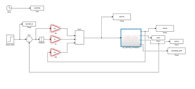
Control design objectives of a DC motor using PID controller are as follows:-
settling time < 2s
overshoot < 5%
steady state error < 1%
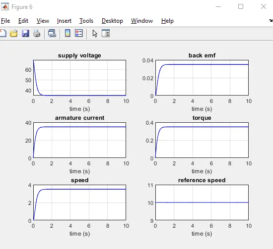
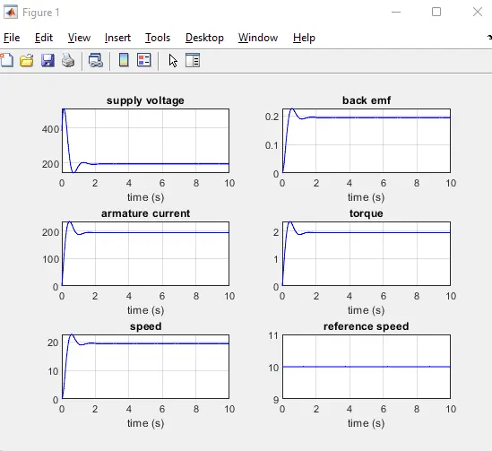
case 1) when Kp = 38.3133, Kd = -2.8584 & Ki = 0.0
Response is shown below:-
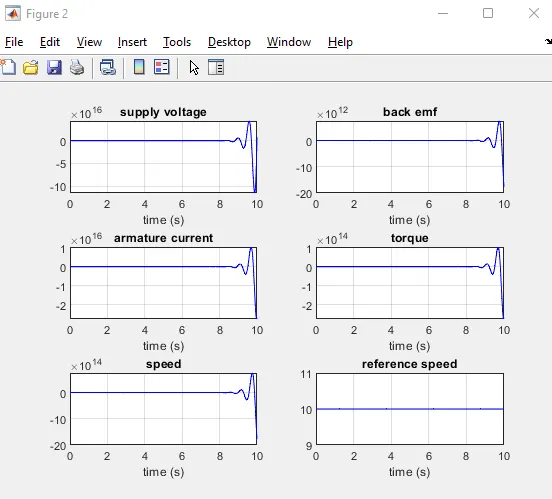
case 2) when Kp = 38.3133, Kd = -2.8584 & Ki = 800.0
Response is shown below:-
case 3)
when Kp = 38.3133, Kd = -2.8584 & Ki = 2500.0
Response is shown below:-
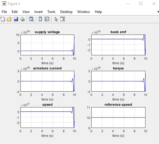
from the above cases, case 1 get overshoot and undershoot,which can be treated as stable system but case 2 and case 3 are not stable.
Let us take zeta value nearly equal to 1 i.e. zeta = 0.9( critically damped):-
case 1) when zeta = 0.9 Kp = 13.1805, Kd = -0.3451, Ki = 0.0
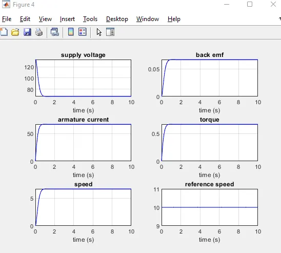
case 1) when zeta = 1.0 Kp = 13.1805, Kd = -0.3451, Ki = 0.0