Project - Speed Control of a Direct Current (DC) motor
1.
In this project, a Simulink model for the DC motor will be first developed per the schematic shown in Figure 1.Use the Proportional, Integral, and Derivative (PID) control design knowledge gained in the training to design, develop and test a controller to maintain a desired speed for the motor.
- Here the Speed control of a DC motor is either done manually by the operator or by means of an automatic control device.
- so the speed can be varied by changing:
- The terminal voltage of the armature V
- The external resistance in armature circuit Ra
- The flux per pole.
i Difine the basic Parameters in Workspace.
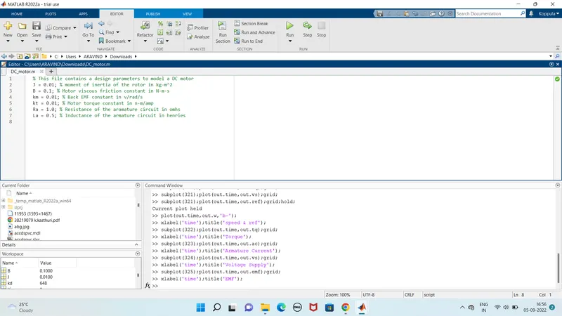
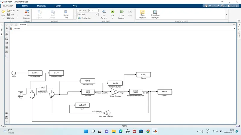
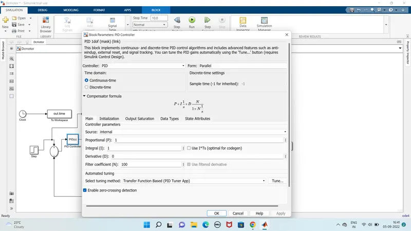
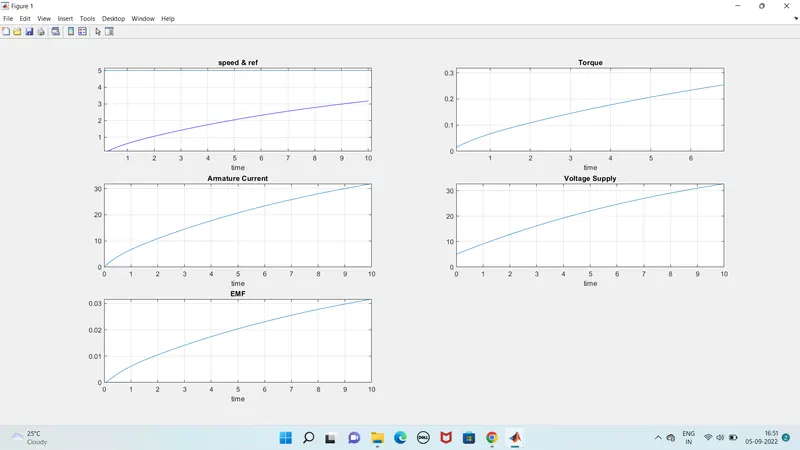
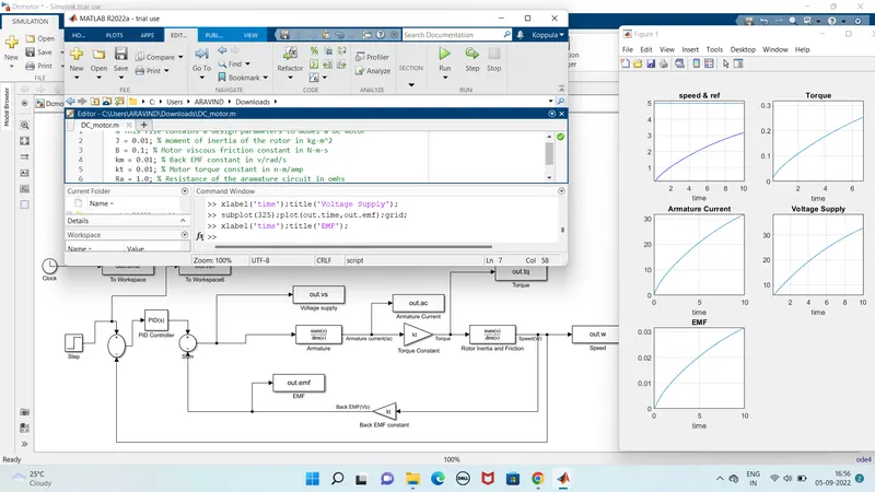
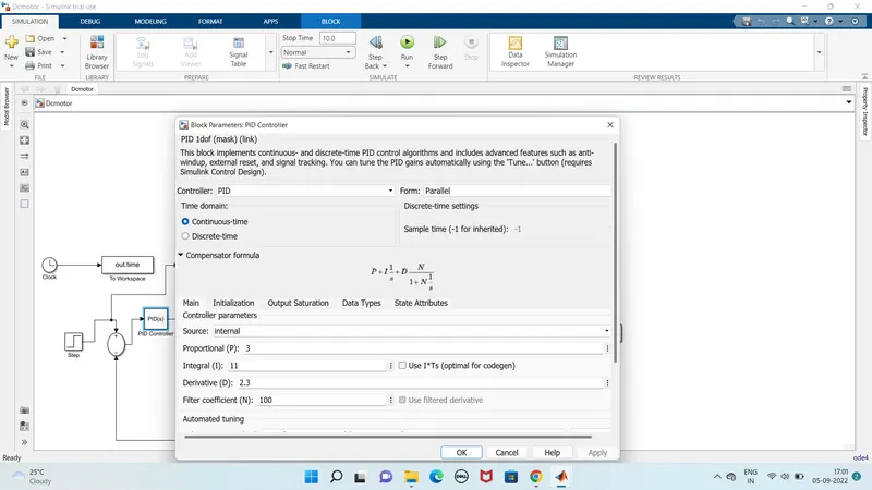
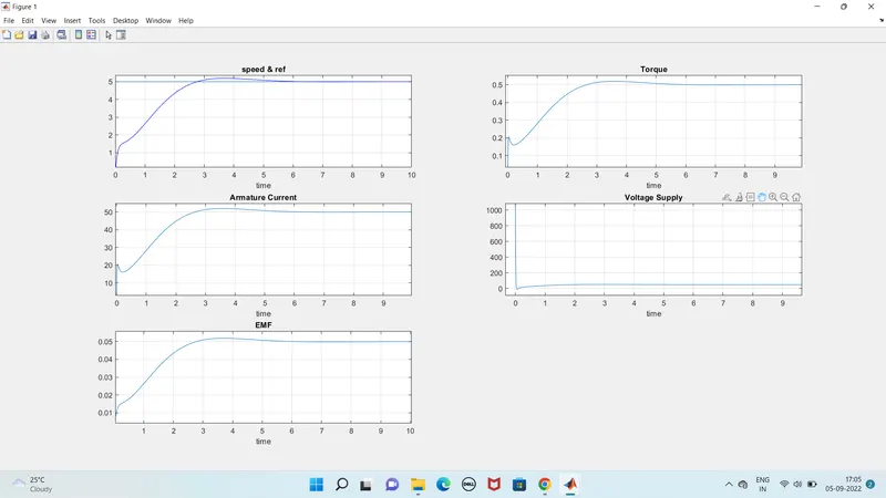
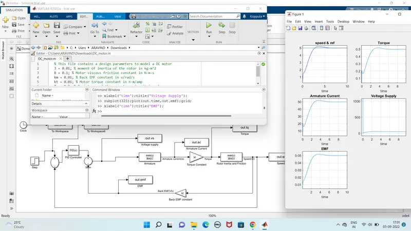
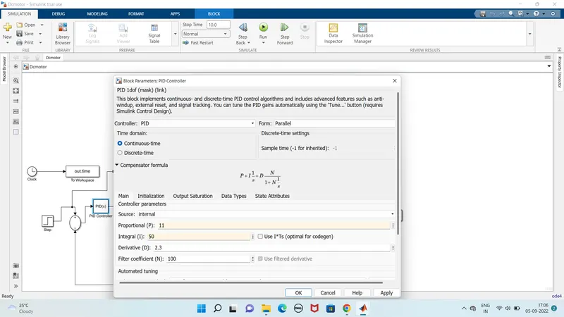
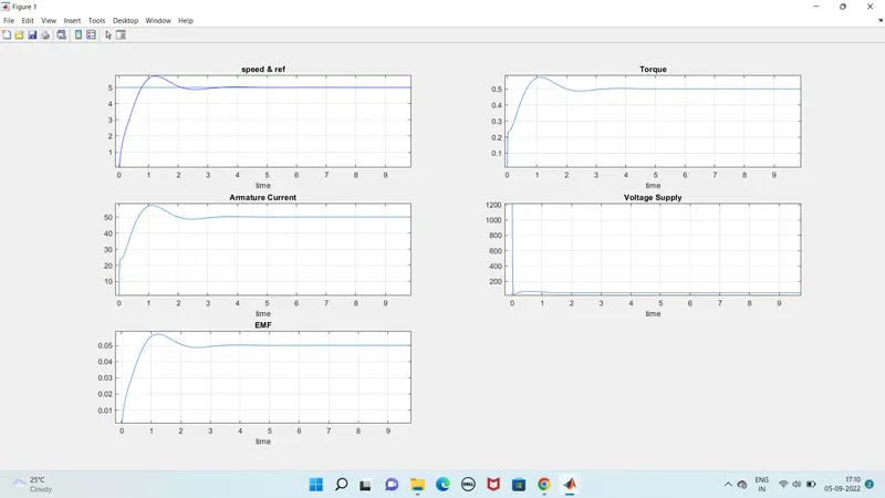
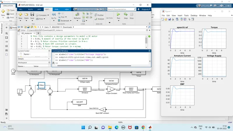
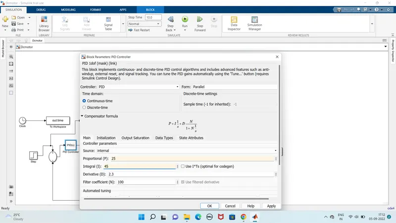
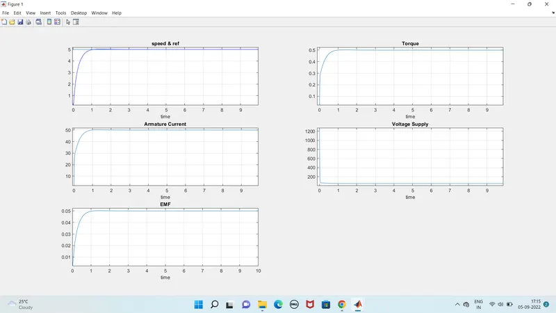
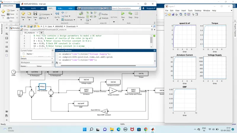
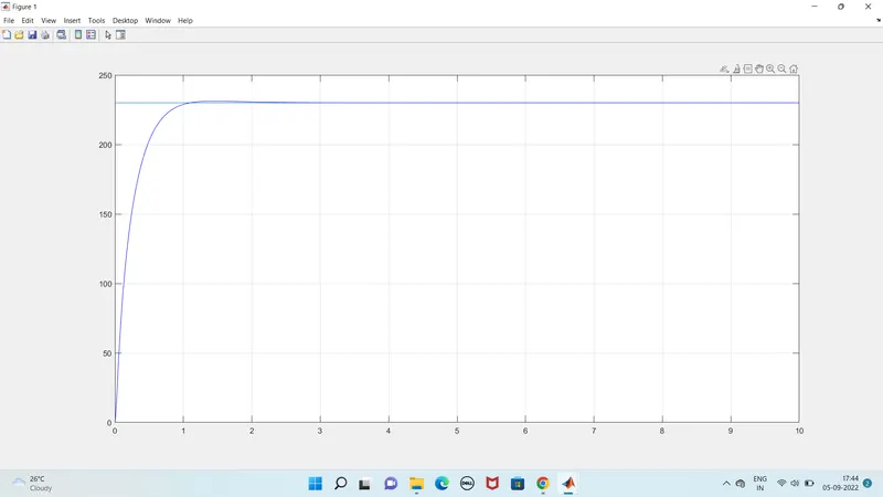
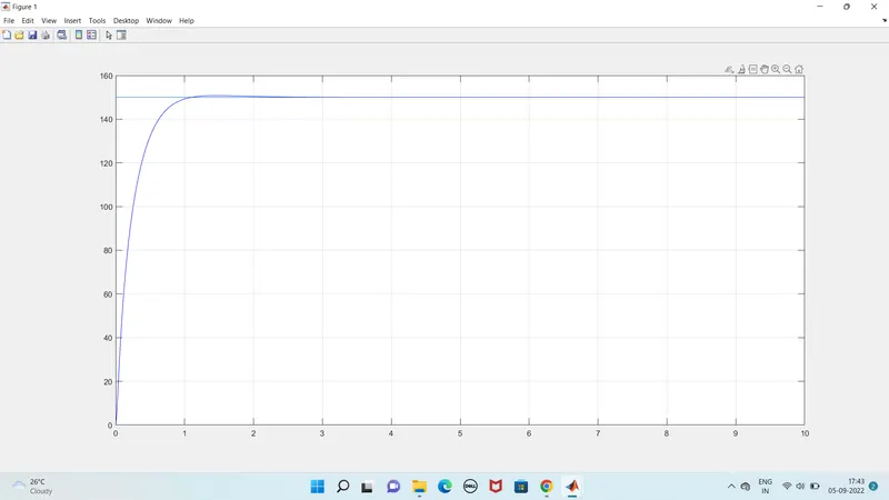
I have used the tools to construct the these models:
a. Clock : output the current simulation time.
b. Constant : Output the constant input value.
c. Step : Output a step.
d. Ramp : Output a Ramp.
e. Sine wave Function : Output a sine wave.
f. Integrator : Continous time integration of input signal.
g. Sum : Add or subtract the inputs.
h. Add : Add or subtract the inputs.
i. X Y grahp : To plot inputs in the X Y graph
j. Scope : Display input signals with respect to the simulation time
k. transfer fcn : It gives the numerator and denominator values.