Project - Speed Control of a Direct Current (DC) motor
Project
Aim: -
Use the Proportional, Integral, and Derivative (PID) control design knowledge gained in the training to design, develop and test a controller to maintain a desired speed for the motor.
Solution:
PID Control of a DC Motor
DC Machine:
- A DC machine functions as a generator or motor.
- Rotor with an armature winding providing the electric circuited.
- Stator with field winding serves as a magnet when energized.
- A prime mover is coupled with the rotor, allowing it to rotate in the magnetic field created by the field winding.
- This mechanism induces EMF in the conductors mounted on the rotor contributing to voltage generation.
- The electrical energy supplied to armature winding and the field winding contributes to a rotating magnetic field that forces the rotor to rotate.
When a Mechanical Load is applied:
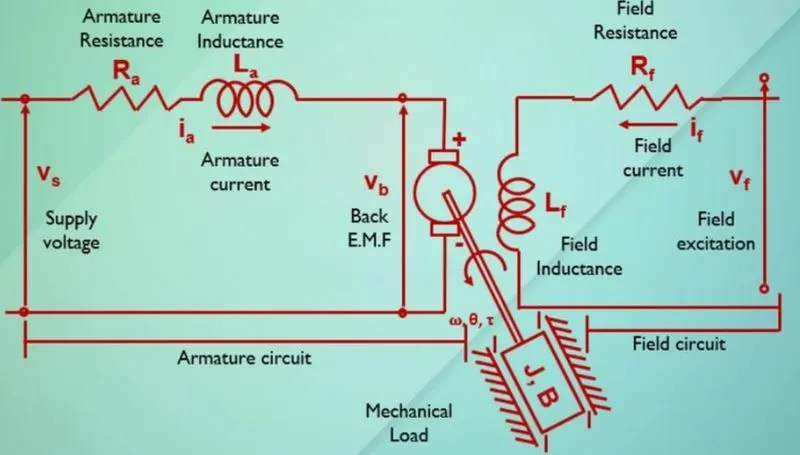
- Using Krichoff’s voltage law, one can derive
Vs = Ra.ia + La + Vb
Vs = Supply Voltage
Ra = Armature Resistance
Ia = Armature Current
La = Armature Inductance
Vb = Back EMF.
- Back EMF, angular velocity, and torque are related by,
Vb = Km t =kti
- Here km and kt are the back EMF and torque constant.
- The open loop transfer function for the motor with the speed (w) and supply voltage (Vs) can be derived as,
- A PID controller design is demonstrated to obtain the desired angular speed using the appropriate supply voltage.
PID – Design for speed control of a DC motor:
- Build a Simulink model of PID controller to regulate the speed of the DC Motor.
- We will assume that the input of the system is the voltage source (V) applied to the motor's armature, while the output is the rotational speed of the shaft.
- Assume a viscous friction model, that is, the friction torque is proportional to shaft angular velocity.
- The physical parameters for our example are:
(J) Moment of inertia of the rotor 0.01 kg.m^2
(b) Motor viscous friction constant 0.1 N.m.s
(Ke) electromotive force constant 0.01 V/rad/sec
(Kt) motor torque constant 0.01 N.m/Amp
(R) Electric resistance 1 Ohm
(L) Electric inductance 0.5 H
- The torque generated by a DC motor is proportional to the armature current and the strength of the magnetic field.
- The open loop transfer function for the motor with the speed (w) and supply voltage (Vs) can be derived as,
- A PID controller design is demonstrated to obtain the desired angular speed using the appropriate supply voltage.
- For a unit step command in motor speed, the control system's output should meet the following requirements.
Settling time less than 2 seconds
Overshoot less than 5%
Steady-state error less than 1%
MATLAB representation
- We can represent the above open-loop transfer function of the motor in MATLAB by defining the parameters and transfer function as follows. Running this code in the command window produces the output shown below.
% Design Parameters
J=0.01;
B=0.1;
Km=0.01;
Kt=0.01;
Ra=1.0;
La=0.5;
- Save the file as ‘pid_controller.m’.
Simulink Model
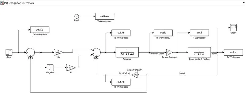
- The range of numbers 0:0.1:5 specify that the step response plot should include data points for times from 0 to 5 seconds in steps of 0.1 seconds. The resulting plot is shown in the figure below,
- Save the simulated file and run
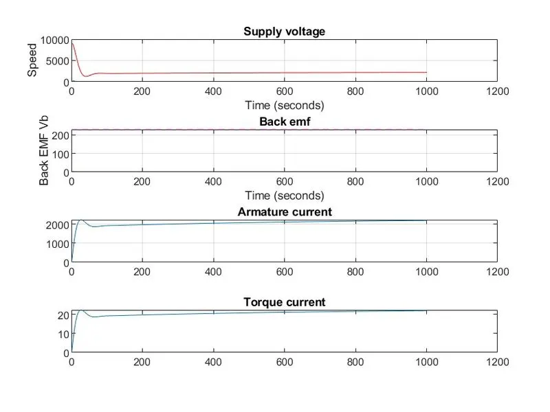
- The plots are prepared in matlab by using various plotting parameters. Are discussed below.
% Plot the outputs
%Plot Supply Voltage and speed
subplot(411);
plot(out.w);grid;hold;
plot(out.Vs,'r-');title('Supply voltage');
%Plot Back emf
subplot(412);
plot(out.Vb,'b-');grid;title('Back emf');hold;
plot(out.Cs,'m--');
% Plot Armature current
subplot(413);grid;
plot(out.la);title('Armature current');grid;
%Plot Torque Current
subplot(414);grid;
plot(out.i);title('Torque current');
- The plotted graph as shown below.
Conclusion:
Overall, this response seems to meet our goals of bringing the PID speed control of DC machine. The various responses are explained with detailed plots of various parameters of dc machine.