Project - Speed Control of a Direct Current (DC) motor
Sol.1
Script:
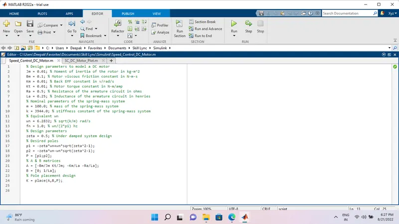
% Design parameters to model a DC motor
Jm = 0.01; % Moment of inertia of the rotor in kg-m^2
Bm = 0.1; % Motor viscous friction constant in N-m-s
Km = 0.01; % Back EMF constant in v/rad/s
Kt = 0.01; % Motor torque constant in N-m/amp
Ra = 0.5; % Resistance of the armature circuit in ohms
La = 0.25; % Inductance of the armature circuit in henries
% Nominal parameters of the spring-mass system
m = 100.0; % mass of the spring-mass system
k = 3944.0; % stiffness constant of the spring-mass system
% Equivalent wn
wn = 6.2832; % sqrt(k/m) rad/s
fn = 1.0; % wn/(2*pi) hz
% Design parameters
zeta = 0.5; % Under damped system design
% Desired poles
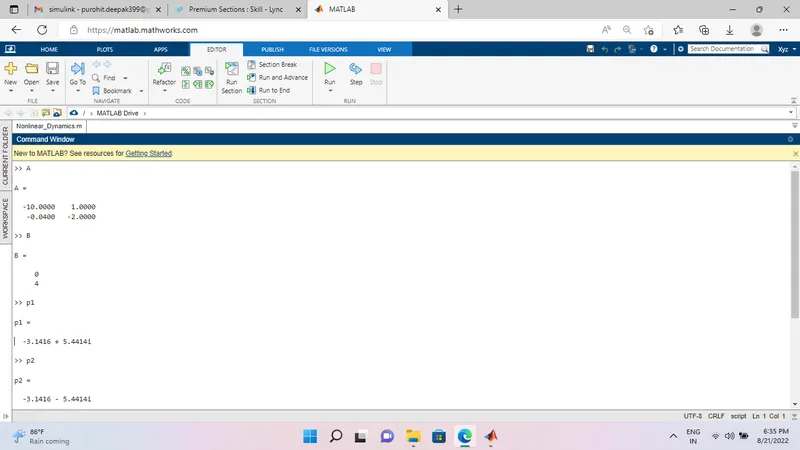
p1 = -zeta*wn+wn*sqrt(zeta^2-1);
p2 = -zeta*wn-wn*sqrt(zeta^2-1);
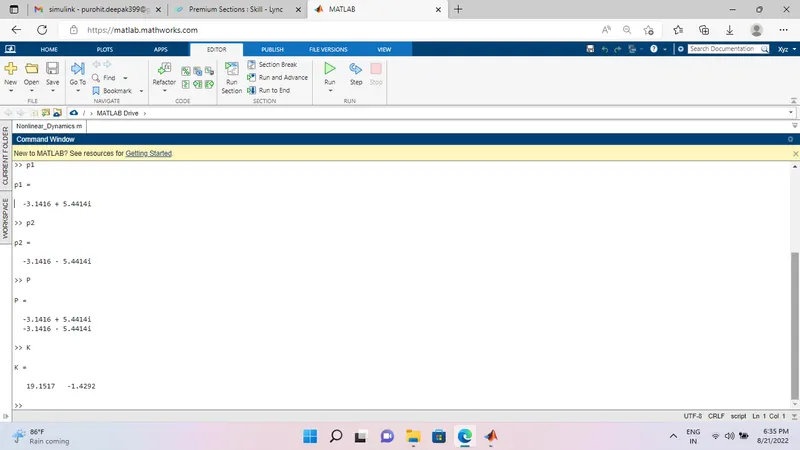
P = [p1;p2];
% A & B matrices
A = [-Bm/Jm Kt/Jm; -Km/La -Ra/La];
B = [0; 1/La];
% Pole placement design
K = place(A,B,P);
For Plot:
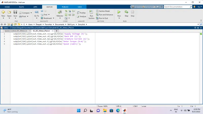
subplot(321);plot(out.time,out.vs);grid;title('Supply Voltage (V)');
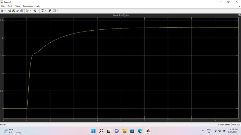
subplot(322);plot(out.time,out.vb);grid;title('Back EMF (V)');
subplot(323);plot(out.time,out.ia);grid;title('Armature Current (A)');
subplot(324);plot(out.time,out.t);grid;title('Motor Torque (N-m)');
subplot(325);plot(out.time,out.w);grid;title('Speed (rad/s)');
Short Summary:
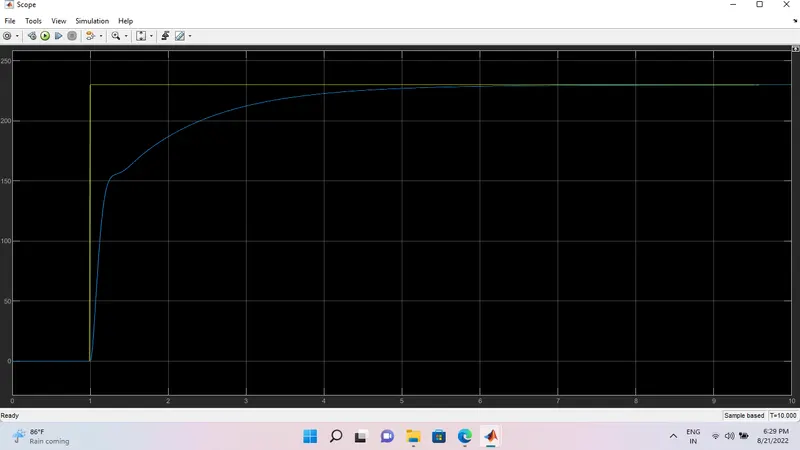
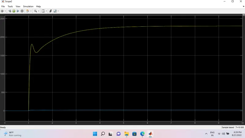
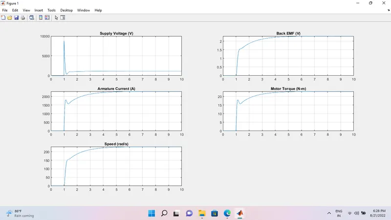
1). In this question first I made a script file for design & plot the graph and write the program then run the script and I received a plot.
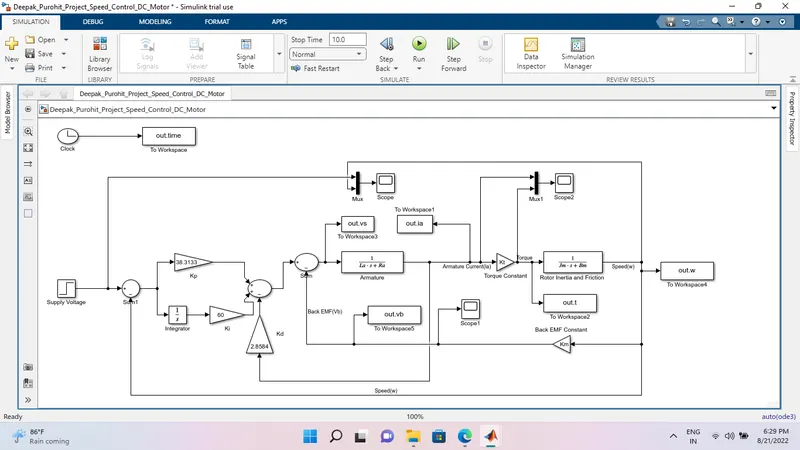
2). I made the program in Simulink according to the PID controller to maintain a desired speed for the motor.
3). I made a program for P, I, and D gains and placed command of K then find the value of Kp, Kd.
4). In this question I used Step, Gain, Integrator, Workspace, Transfer function, Sum, Mux, and also Scope blocks.
5). I used supply voltage 230V.
6). I used imaginary value in Ki gains.
Plot Graph:
Program:
Scope: